EP1170100A2 - Dispositif pour fraiser des rainures dans des poutres en bois, pour l'insertion de poutres métalliques ou analogue - Google Patents
Dispositif pour fraiser des rainures dans des poutres en bois, pour l'insertion de poutres métalliques ou analogue Download PDFInfo
- Publication number
- EP1170100A2 EP1170100A2 EP00128229A EP00128229A EP1170100A2 EP 1170100 A2 EP1170100 A2 EP 1170100A2 EP 00128229 A EP00128229 A EP 00128229A EP 00128229 A EP00128229 A EP 00128229A EP 1170100 A2 EP1170100 A2 EP 1170100A2
- Authority
- EP
- European Patent Office
- Prior art keywords
- milling cutter
- carriage
- milling
- beams
- wood
- Prior art date
- Legal status (The legal status is an assumption and is not a legal conclusion. Google has not performed a legal analysis and makes no representation as to the accuracy of the status listed.)
- Withdrawn
Links
- 238000003801 milling Methods 0.000 title claims abstract description 91
- 239000002023 wood Substances 0.000 title claims abstract description 44
- 238000003780 insertion Methods 0.000 title claims abstract description 13
- 230000037431 insertion Effects 0.000 title claims abstract description 13
- 238000004140 cleaning Methods 0.000 claims 1
- XEEYBQQBJWHFJM-UHFFFAOYSA-N Iron Chemical compound [Fe] XEEYBQQBJWHFJM-UHFFFAOYSA-N 0.000 description 6
- 238000003754 machining Methods 0.000 description 4
- 229910052742 iron Inorganic materials 0.000 description 3
- 238000004519 manufacturing process Methods 0.000 description 2
- 230000009471 action Effects 0.000 description 1
- 230000002860 competitive effect Effects 0.000 description 1
- 230000000670 limiting effect Effects 0.000 description 1
- 239000000463 material Substances 0.000 description 1
- 238000000034 method Methods 0.000 description 1
- 238000012986 modification Methods 0.000 description 1
- 230000004048 modification Effects 0.000 description 1
- 230000008569 process Effects 0.000 description 1
Images

Classifications
-
- B—PERFORMING OPERATIONS; TRANSPORTING
- B23—MACHINE TOOLS; METAL-WORKING NOT OTHERWISE PROVIDED FOR
- B23Q—DETAILS, COMPONENTS, OR ACCESSORIES FOR MACHINE TOOLS, e.g. ARRANGEMENTS FOR COPYING OR CONTROLLING; MACHINE TOOLS IN GENERAL CHARACTERISED BY THE CONSTRUCTION OF PARTICULAR DETAILS OR COMPONENTS; COMBINATIONS OR ASSOCIATIONS OF METAL-WORKING MACHINES, NOT DIRECTED TO A PARTICULAR RESULT
- B23Q11/00—Accessories fitted to machine tools for keeping tools or parts of the machine in good working condition or for cooling work; Safety devices specially combined with or arranged in, or specially adapted for use in connection with, machine tools
- B23Q11/0042—Devices for removing chips
- B23Q11/0046—Devices for removing chips by sucking
-
- B—PERFORMING OPERATIONS; TRANSPORTING
- B27—WORKING OR PRESERVING WOOD OR SIMILAR MATERIAL; NAILING OR STAPLING MACHINES IN GENERAL
- B27C—PLANING, DRILLING, MILLING, TURNING OR UNIVERSAL MACHINES FOR WOOD OR SIMILAR MATERIAL
- B27C5/00—Machines designed for producing special profiles or shaped work, e.g. by rotary cutters; Equipment therefor
-
- B—PERFORMING OPERATIONS; TRANSPORTING
- B27—WORKING OR PRESERVING WOOD OR SIMILAR MATERIAL; NAILING OR STAPLING MACHINES IN GENERAL
- B27M—WORKING OF WOOD NOT PROVIDED FOR IN SUBCLASSES B27B - B27L; MANUFACTURE OF SPECIFIC WOODEN ARTICLES
- B27M1/00—Working of wood not provided for in subclasses B27B - B27L, e.g. by stretching
- B27M1/08—Working of wood not provided for in subclasses B27B - B27L, e.g. by stretching by multi-step processes
Definitions
- the present invention relates to an apparatus for forming millings in wood beams, for the insertion of metallic beams and the like.
- Conventional wood beams are often used directly in view as a decorative element of a room at its ceiling, even though they do not have an actual supporting structural function.
- wood beams which have a rectangular or square cross-section are usually used and a milling is performed in said beams so as to form a seat for the metallic beam, which is then inserted along the wood beam.
- the support is provided by the metallic beam, which is tied to the walls of the room, while the wood beam that covers it externally is designed to allow the presence of a structural element such as a metallic beam to be aesthetically pleasant to the eye and also to contribute to the load-bearing capacity of the floor.
- the aim of the present invention is to provide an apparatus for forming millings in wood beams for the insertion of metallic beams and the like which is able to perform the various millings in a single step.
- an object of the present invention is to provide an apparatus for forming millings in wood beams for the insertion of metallic beams and the like in which said millings are performed not only in a single machining pass but also without the need to perform complicated centerings of the beam with respect to the milling cutters.
- Another object of the present invention is to provide an apparatus for forming millings in wood beams which is simple to maintain.
- Another object of the present invention is to provide an apparatus for forming millings in wood beams which allows to remove substantially most of the chips formed by the milling process so that said chips cannot scatter into the surrounding space.
- Another object of the present invention is to provide an apparatus for forming millings in wood beams which is highly reliable, relatively simple to manufacture and at competitive costs.
- an apparatus for forming millings in wood beams for the insertion of metallic beams characterized in that it comprises a carriage movable along rails and adapted to support at least one milling cutter for forming a milling along a wood beam which is arranged so as to be fixed between said rails, centrally with respect to said carriage, said at least one milling cutter being provided with means for adjusting the position of said at least one milling cutter with respect to said wood beam.
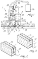
- the apparatus generally designated by the reference numeral 1, comprises a carriage 2 which can move by means of wheels 3 along two rails 4, for example by way of a rack-type actuation system, wherein the rack, designated by the reference numeral 5, is arranged below at least one of the rails, and a pinion 6 actuated by motor means 7 engages said rack in order to drive the wheels 3 along the rack.
- the wheels 3 are driven by means of a supporting arm 8 which is rigidly coupled to the frame of the wheel and is provided with a sprocket 9 at one of its ends, which is located at the rack 5.
- the sprocket 9 thus engages the rack 5, and by actuation by means of the pinion 6 drives the wheels 3 of the carriage 2 along the rails 4.
- the carriage 2 is centrally open in order to allow passage over a wood beam 10 which is arranged in a fixed position between the rails and in which the millings are to be provided, as shown for example in Figures 2 and 3.
- Figure 2 shows a milling 11 which is T-shaped so as to allow the insertion of a metallic beam 12 which has a similar cross-section.
- Figure 3 instead illustrates a wood beam 10 with a milling 11 which is H-shaped for the insertion of a metallic beam 12 which has a similar cross-section.
- the wood beam 10 is thus arranged centrally with respect to the carriage 2 and is locked in position by way of locking means which are conveniently provided for example by an abutment 15 which is fixed at one side of the wood beam 10 and by a piston 16 which can be adjusted so as to adapt to the different dimensions of the beam 10.
- the carriage 2 supports a first vertical milling cutter 18 connected to an arm 45 which is vertically adjustable by means of the actuation of a worm screw 19.
- Actuation can be manual, by means of a handwheel 20, as shown in the figures, or can be, for example, motorized.
- the rotation of the vertical milling cutter 18 is achieved by way of motor means 21 by means of a belt 32.
- the vertical milling cutter 18 is suitable to provide, in the wood beam 10, the vertical milling that corresponds to the portion of the milling 11 of the T or H shown in Figures 2 and 3.
- the worm screw 19 thus allows to vertically adjust the vertical milling cutter 18 in order to adjust the depth of the vertical milling 11.
- the horizontal millings which are perpendicular to the milling provided by means of the vertical milling cutter 18
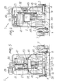
- at least one horizontal milling cutter or, as shown in the figures there are provided two horizontal milling cutters 22 which are also vertically adjustable by means of the translatory motion of a supporting arm 23 along a second worm screw 24.
- the adjustment can be motorized, by way of motor means 25, as shown in the figures, or can be manual by means of a handwheel which is similar to the handwheel 20.
- the rotation of the horizontal milling cutters 22 is determined by motor means 26.
- the vertical central milling cutter 18 performs the vertical milling, while the horizontal milling cutters 22 produce the horizontal millings, which are perpendicular to the preceding milling.
- the metallic beams 12 can then be inserted along the entire wood beam, since the carriage 2 which can move along the rails 4 allows the mills to perform the milling along the entire length of the wood beam 10.
- the vertical milling cutter 18 can be set at an angle, by means of the rotation of a plate 28 which is rigidly coupled to the arm 19 that supports the milling cutter 18, with respect to a plate 27 which is rigidly coupled to the worm screw 19.
- the rotation of the plate 28 with respect to the plate 27 allows to set the central milling cutter 18 at a selected angle with respect to the vertical axis that is perpendicular to the upper surface of the wood beam 10.
- suction intakes 30 and 31 are respectively provided, being located at the milling cutters 18 and 22 and which, by means of hoses 33 and 34, allow to convey the chips to a common hose 35 which leads into a collection tank 36.
- At least one of the wheels and preferably each one of the wheels 3, has a brush 37 which is rigidly connected to the arm 8 and is moved along the rail, rubbing against it.
- the carriage 2 and the rails 4 are supported by a footing 38 which allows to keep the rails 4 raised from the ground and therefore allows to position the pinion 6 under the rack 5 that is present on at least one the rails 4.
- the wood beam 10 is positioned centrally with respect to the carriage 2, between the rails 4, on a supporting surface 40 which connects the rails 4 to each other and is supported by the footing or preferably by the pair of footings 38.
- the wood beam 10 is rigidly locked in position by means of the fixed abutment 15 and the piston 16, and the carriage 2 is made to advance by acting on the rack 5 by means of the pinion 6.
- the advancement of the carriage 2 along the rails 4 places the vertical milling cutter 18 in contact with the wood beam 10, and the actuation of the milling cutter by way of the motor means 21 and the belt 32 allows to perform the vertical milling along the entire length of the wood beam 10 or along the selected portion of the wood beam.
- the horizontal milling cutters 22 driven by the motor means 26 start to operate successively and synchronously and perform the horizontal millings, which are perpendicular in the millings formed by the vertical milling cutter 18.
- the position of the millings can be selected at will by the operator by acting on the worm screws 19 and 24, which respectively adjust the height of the vertical milling cutter 18 and of the horizontal milling cutter or cutters 22 with respect to the wood beam 10.
- the suction intakes 30 and 31 allow to aspirate the chips formed by the milling operations as the millings are formed, thus allowing to keep the surrounding space substantially clean.
- the apparatus according to the present invention fully achieves the intended aim and objects, since it allows to perform all the milling operations required for the insertion of a metallic beam in a wood beam in a single pass, without machining downtimes, and with an apparatus which is not structurally complicated.
- the means for adjusting the position of the milling cutters with respect to the beam further allow to center the millings at will.
- the materials employed may be any according to requirements and to the state of the art.
Landscapes
- Engineering & Computer Science (AREA)
- Life Sciences & Earth Sciences (AREA)
- Mechanical Engineering (AREA)
- Wood Science & Technology (AREA)
- Forests & Forestry (AREA)
- Optical Head (AREA)
- Milling, Drilling, And Turning Of Wood (AREA)
- Manufacture Of Wood Veneers (AREA)
Applications Claiming Priority (2)
| Application Number | Priority Date | Filing Date | Title |
|---|---|---|---|
| IT2000MI001323A IT1318019B1 (it) | 2000-06-13 | 2000-06-13 | Apparecchiatura per la realizzazione di fresature in travi di legno,per l'inserimento di putrelle e simili. |
| ITMI201323 | 2000-06-13 |
Publications (2)
| Publication Number | Publication Date |
|---|---|
| EP1170100A2 true EP1170100A2 (fr) | 2002-01-09 |
| EP1170100A3 EP1170100A3 (fr) | 2003-03-12 |
Family
ID=11445251
Family Applications (1)
| Application Number | Title | Priority Date | Filing Date |
|---|---|---|---|
| EP00128229A Withdrawn EP1170100A3 (fr) | 2000-06-13 | 2000-12-27 | Dispositif pour fraiser des rainures dans des poutres en bois, pour l'insertion de poutres métalliques ou analogue |
Country Status (2)
| Country | Link |
|---|---|
| EP (1) | EP1170100A3 (fr) |
| IT (1) | IT1318019B1 (fr) |
Cited By (3)
| Publication number | Priority date | Publication date | Assignee | Title |
|---|---|---|---|---|
| KR20020026236A (ko) * | 2002-03-18 | 2002-04-06 | 김용성 | 문틀의 커팅홈 가공기 |
| KR20030067336A (ko) * | 2002-02-08 | 2003-08-14 | 이오희 | 목재의 가공장치 |
| CN108890792A (zh) * | 2018-05-30 | 2018-11-27 | 东莞市联洲知识产权运营管理有限公司 | 一种切割可移动木板切割架 |
Citations (4)
| Publication number | Priority date | Publication date | Assignee | Title |
|---|---|---|---|---|
| FR1066547A (fr) * | 1952-11-14 | 1954-06-08 | Machine portative à moiser | |
| FR1432740A (fr) * | 1965-02-11 | 1966-03-25 | Installation de polissage de pierres et matériaux similaires | |
| FR2294813A1 (fr) * | 1974-12-20 | 1976-07-16 | Legrand Roger | Procede de realisation d'une rainure en t dans l'epaisseur d'une planche et dispositif correspondant |
| DE3024701A1 (de) * | 1980-06-30 | 1982-01-28 | Industrie-Planungs-Gesellschaft Mbh, 8380 Landau | Vorrichtung zum abbinden von hoelzern, wandteilen o.dgl. |
-
2000
- 2000-06-13 IT IT2000MI001323A patent/IT1318019B1/it active
- 2000-12-27 EP EP00128229A patent/EP1170100A3/fr not_active Withdrawn
Patent Citations (4)
| Publication number | Priority date | Publication date | Assignee | Title |
|---|---|---|---|---|
| FR1066547A (fr) * | 1952-11-14 | 1954-06-08 | Machine portative à moiser | |
| FR1432740A (fr) * | 1965-02-11 | 1966-03-25 | Installation de polissage de pierres et matériaux similaires | |
| FR2294813A1 (fr) * | 1974-12-20 | 1976-07-16 | Legrand Roger | Procede de realisation d'une rainure en t dans l'epaisseur d'une planche et dispositif correspondant |
| DE3024701A1 (de) * | 1980-06-30 | 1982-01-28 | Industrie-Planungs-Gesellschaft Mbh, 8380 Landau | Vorrichtung zum abbinden von hoelzern, wandteilen o.dgl. |
Cited By (3)
| Publication number | Priority date | Publication date | Assignee | Title |
|---|---|---|---|---|
| KR20030067336A (ko) * | 2002-02-08 | 2003-08-14 | 이오희 | 목재의 가공장치 |
| KR20020026236A (ko) * | 2002-03-18 | 2002-04-06 | 김용성 | 문틀의 커팅홈 가공기 |
| CN108890792A (zh) * | 2018-05-30 | 2018-11-27 | 东莞市联洲知识产权运营管理有限公司 | 一种切割可移动木板切割架 |
Also Published As
| Publication number | Publication date |
|---|---|
| ITMI20001323A1 (it) | 2001-12-13 |
| EP1170100A3 (fr) | 2003-03-12 |
| IT1318019B1 (it) | 2003-07-21 |
| ITMI20001323A0 (it) | 2000-06-13 |
Similar Documents
| Publication | Publication Date | Title |
|---|---|---|
| CN111745095B (zh) | 一种用于钢筋等距切割分段的设备 | |
| US5318005A (en) | Apparatus for cutting plate-shaped workpieces and for edge processing thereof | |
| EP2039464A1 (fr) | Machine automatique et procédé automatique pour meuler le bord périmétrique de feuilles de verre | |
| CN111409123B (zh) | 一种具备调节功能的汽车脚垫切割机 | |
| US4102374A (en) | Jig and template apparatus and method for preparing a corner insert for a laminated plastic countertop | |
| EP1170100A2 (fr) | Dispositif pour fraiser des rainures dans des poutres en bois, pour l'insertion de poutres métalliques ou analogue | |
| US4541405A (en) | Hydraulic stone shaping machine | |
| EP1172179A2 (fr) | Dispositif de serrage pour ensembles de cadres | |
| KR102501218B1 (ko) | 프로파일 요소를 용접하기 위한 기계 | |
| US4763703A (en) | Apparatus for cutting miters on trim members | |
| US7677149B2 (en) | Coping apparatus and method of operation | |
| KR101568253B1 (ko) | 창틀 중간프레임의 절단 및 연마장치 | |
| JPH09216191A (ja) | 畳床両框裁断装置 | |
| KR101896402B1 (ko) | 산업용 프레임 천공장치 | |
| EP0921916B1 (fr) | Appareil permettant d'usiner des panneaux verticaux | |
| AU2003257887A1 (en) | Attachment Fixture for Manufacturing Elliptical Arches Using a Single-pass Radius Molding System | |
| KR102623258B1 (ko) | 건축용 장식부재의 표면 가공장치 | |
| GB2283193A (en) | Profile trimming apparatus | |
| US6076574A (en) | Machine for shaping curved molding | |
| KR19990035081U (ko) | 신발창의홈연삭가공기 | |
| EP0494039A2 (fr) | Scie d'onglets à lame de scie circulaire | |
| CN219190787U (zh) | 一种异形石材加工装置 | |
| JP4002111B2 (ja) | バックゲージ装置 | |
| CN216803565U (zh) | 一种窗帘生产用剪裁装置 | |
| JPH0723193Y2 (ja) | 切断装置 |
Legal Events
| Date | Code | Title | Description |
|---|---|---|---|
| PUAI | Public reference made under article 153(3) epc to a published international application that has entered the european phase |
Free format text: ORIGINAL CODE: 0009012 |
|
| AK | Designated contracting states |
Kind code of ref document: A2 Designated state(s): AT BE CH CY DE DK ES FI FR GB GR IE IT LI LU MC NL PT SE TR |
|
| AX | Request for extension of the european patent |
Free format text: AL;LT;LV;MK;RO;SI |
|
| PUAL | Search report despatched |
Free format text: ORIGINAL CODE: 0009013 |
|
| AK | Designated contracting states |
Kind code of ref document: A3 Designated state(s): AT BE CH CY DE DK ES FI FR GB GR IE IT LI LU MC NL PT SE TR Designated state(s): AT BE CH CY DE DK ES FI FR GB GR IE IT LI LU MC NL PT SE TR |
|
| AX | Request for extension of the european patent |
Extension state: AL LT LV MK RO SI |
|
| RIC1 | Information provided on ipc code assigned before grant |
Ipc: 7E 04C 3/18 B Ipc: 7B 23Q 1/01 B Ipc: 7B 27C 9/04 B Ipc: 7B 27F 1/02 B Ipc: 7B 23Q 11/00 B Ipc: 7B 23D 45/10 B Ipc: 7B 27M 1/08 B Ipc: 7B 27C 5/00 A |
|
| AKX | Designation fees paid | ||
| REG | Reference to a national code |
Ref country code: DE Ref legal event code: 8566 |
|
| STAA | Information on the status of an ep patent application or granted ep patent |
Free format text: STATUS: THE APPLICATION IS DEEMED TO BE WITHDRAWN |
|
| 18D | Application deemed to be withdrawn |
Effective date: 20030913 |