EP1170091B1 - Senkerwerkzeug - Google Patents
Senkerwerkzeug Download PDFInfo
- Publication number
- EP1170091B1 EP1170091B1 EP01114535A EP01114535A EP1170091B1 EP 1170091 B1 EP1170091 B1 EP 1170091B1 EP 01114535 A EP01114535 A EP 01114535A EP 01114535 A EP01114535 A EP 01114535A EP 1170091 B1 EP1170091 B1 EP 1170091B1
- Authority
- EP
- European Patent Office
- Prior art keywords
- tool
- intermediate piece
- tool according
- abrasive coating
- chamfering tool
- Prior art date
- Legal status (The legal status is an assumption and is not a legal conclusion. Google has not performed a legal analysis and makes no representation as to the accuracy of the status listed.)
- Expired - Lifetime
Links
- 239000004033 plastic Substances 0.000 claims description 72
- 229920003023 plastic Polymers 0.000 claims description 72
- 239000011248 coating agent Substances 0.000 claims description 33
- 238000000576 coating method Methods 0.000 claims description 33
- 239000011521 glass Substances 0.000 claims description 18
- 238000009826 distribution Methods 0.000 claims description 13
- 239000000463 material Substances 0.000 claims description 11
- 238000013016 damping Methods 0.000 claims description 7
- 239000000853 adhesive Substances 0.000 claims description 3
- 230000001070 adhesive effect Effects 0.000 claims description 3
- 239000012809 cooling fluid Substances 0.000 claims description 3
- 238000003780 insertion Methods 0.000 claims description 2
- 230000037431 insertion Effects 0.000 claims description 2
- 238000003754 machining Methods 0.000 claims 1
- 125000006850 spacer group Chemical group 0.000 description 30
- 230000033001 locomotion Effects 0.000 description 10
- 238000004519 manufacturing process Methods 0.000 description 10
- 230000009467 reduction Effects 0.000 description 8
- 239000010432 diamond Substances 0.000 description 7
- 229910003460 diamond Inorganic materials 0.000 description 6
- 238000000227 grinding Methods 0.000 description 6
- 230000008901 benefit Effects 0.000 description 5
- 230000005489 elastic deformation Effects 0.000 description 4
- 239000002826 coolant Substances 0.000 description 3
- 238000005553 drilling Methods 0.000 description 3
- 230000010355 oscillation Effects 0.000 description 3
- 230000003534 oscillatory effect Effects 0.000 description 3
- 229920001343 polytetrafluoroethylene Polymers 0.000 description 3
- 239000004810 polytetrafluoroethylene Substances 0.000 description 3
- 238000012545 processing Methods 0.000 description 3
- 239000004952 Polyamide Substances 0.000 description 2
- 238000005452 bending Methods 0.000 description 2
- 230000005540 biological transmission Effects 0.000 description 2
- 239000000110 cooling liquid Substances 0.000 description 2
- 230000008878 coupling Effects 0.000 description 2
- 238000010168 coupling process Methods 0.000 description 2
- 238000005859 coupling reaction Methods 0.000 description 2
- 238000005520 cutting process Methods 0.000 description 2
- 229920001971 elastomer Polymers 0.000 description 2
- 230000005284 excitation Effects 0.000 description 2
- 238000010438 heat treatment Methods 0.000 description 2
- 238000007654 immersion Methods 0.000 description 2
- 238000000034 method Methods 0.000 description 2
- 229920002647 polyamide Polymers 0.000 description 2
- -1 polytetrafluoroethylene Polymers 0.000 description 2
- 230000008569 process Effects 0.000 description 2
- 239000005060 rubber Substances 0.000 description 2
- 229920001342 Bakelite® Polymers 0.000 description 1
- 208000031872 Body Remains Diseases 0.000 description 1
- 239000004831 Hot glue Substances 0.000 description 1
- 238000009825 accumulation Methods 0.000 description 1
- 239000004637 bakelite Substances 0.000 description 1
- 230000008859 change Effects 0.000 description 1
- 230000006835 compression Effects 0.000 description 1
- 238000007906 compression Methods 0.000 description 1
- 238000010276 construction Methods 0.000 description 1
- 230000001419 dependent effect Effects 0.000 description 1
- 238000011161 development Methods 0.000 description 1
- 230000018109 developmental process Effects 0.000 description 1
- 239000013013 elastic material Substances 0.000 description 1
- 238000007667 floating Methods 0.000 description 1
- 239000010437 gem Substances 0.000 description 1
- 239000007769 metal material Substances 0.000 description 1
- 238000003801 milling Methods 0.000 description 1
- 230000002093 peripheral effect Effects 0.000 description 1
- 229920000642 polymer Polymers 0.000 description 1
- 238000002360 preparation method Methods 0.000 description 1
- 230000011218 segmentation Effects 0.000 description 1
- 238000005245 sintering Methods 0.000 description 1
- 239000007787 solid Substances 0.000 description 1
- 238000012549 training Methods 0.000 description 1
- 238000011144 upstream manufacturing Methods 0.000 description 1
Images


Classifications
-
- B—PERFORMING OPERATIONS; TRANSPORTING
- B24—GRINDING; POLISHING
- B24B—MACHINES, DEVICES, OR PROCESSES FOR GRINDING OR POLISHING; DRESSING OR CONDITIONING OF ABRADING SURFACES; FEEDING OF GRINDING, POLISHING, OR LAPPING AGENTS
- B24B9/00—Machines or devices designed for grinding edges or bevels on work or for removing burrs; Accessories therefor
- B24B9/02—Machines or devices designed for grinding edges or bevels on work or for removing burrs; Accessories therefor characterised by a special design with respect to properties of materials specific to articles to be ground
- B24B9/06—Machines or devices designed for grinding edges or bevels on work or for removing burrs; Accessories therefor characterised by a special design with respect to properties of materials specific to articles to be ground of non-metallic inorganic material, e.g. stone, ceramics, porcelain
- B24B9/08—Machines or devices designed for grinding edges or bevels on work or for removing burrs; Accessories therefor characterised by a special design with respect to properties of materials specific to articles to be ground of non-metallic inorganic material, e.g. stone, ceramics, porcelain of glass
-
- B—PERFORMING OPERATIONS; TRANSPORTING
- B24—GRINDING; POLISHING
- B24D—TOOLS FOR GRINDING, BUFFING OR SHARPENING
- B24D7/00—Bonded abrasive wheels, or wheels with inserted abrasive blocks, designed for acting otherwise than only by their periphery, e.g. by the front face; Bushings or mountings therefor
- B24D7/10—Bonded abrasive wheels, or wheels with inserted abrasive blocks, designed for acting otherwise than only by their periphery, e.g. by the front face; Bushings or mountings therefor with cooling provisions
-
- B—PERFORMING OPERATIONS; TRANSPORTING
- B24—GRINDING; POLISHING
- B24D—TOOLS FOR GRINDING, BUFFING OR SHARPENING
- B24D7/00—Bonded abrasive wheels, or wheels with inserted abrasive blocks, designed for acting otherwise than only by their periphery, e.g. by the front face; Bushings or mountings therefor
- B24D7/18—Wheels of special form
Definitions
- the present invention relates to a countersink tool according to the preamble of claim 1.
- FR-A-2 013 231 is a combined drilling and milling tool according to the preamble of claim 1.
- WO 98/57771 A describes a drilling tool for cutting a round hole, with a cylindrical tool neck of non-metallic Material.
- the drilling tool consists of a cylindrical tube, which front with a cutting surface or The like is provided.
- the plastic adapter serves practically as a coupling between the work spindle and the abrasive coating and consumes the occurring vibration excitations, so to speak within of its own volume, as it is compared to the other at the Oscillation movement involved machine and tool components is relatively flexible. Nevertheless, that will be Plastic spacer at best in the elastic range deform, since it consists of a pressure-resistant plastic, which always withstands the feed forces.
- suitable Plastic can be considered Bakelite, for example.
- materials such as rubber, polyamide, PTFE (polytetrafluoroethylene) are and others conceivable.
- a basic principle of the invention is based on Considering that by the internal damping of the plastic the machine tool, in particular the spindle carrier and the tool spindle is significantly less bending under the present feed forces, since a part of the respective Feed of elastic deformation of the plastic intermediate piece recorded and consumed there.
- the Plastic adapter should be used in industrial Range of channels interspersed to be communicating Flow connection between a usually axial Produce inflow channel and the abrasive coating.
- the invention avoids, among other things, a floating of the diamond coating, which comes about during processing, that small and smallest chips of glass removal add to the coating. These chips practically fill the spaces between the chips Diamonds off and stick to the surface of the tool, so that the diamond tips practically no longer in the production the reduction can be involved. This condition will Usually not detected by the machine tools, so that the feed drive despite reduced grinding ability of Abrasive lining continues to run.
- the resulting high pressures can in conjunction with the elasticity not designed for this type of operation the machines trigger the feared vibrations.
- the abrasive coating can be added between the spaces do not free the grinding diamond on its own, so that this operating condition is extremely unpleasant.
- the plastic adapter gives according to its pressure-elastic properties and thus enables the release of the removal.
- the invention also takes into account the Course of the diamond sharpness over the life of the tool.
- Another advantage of the invention is the adaptability to different head angle of the countersink tool. This is understood to mean the cone angle with which the Tool head faces the workpiece and its apex lies on the geometric axis of rotation of the countersink tool.
- This head angle can be in the range between 0 ° and 180 ° lie and thus an almost arbitrary value within this Take limits. In such countersinking tools separates However, a head angle of 0 ° as well as a head angle of 180 °.
- the head angle is in the range between about 30 ° to about 130 °, preferably at about 120 °, provided that subsidence manufacture for the above-mentioned fastening systems want.
- a preferred embodiment differentiates the invention in two embodiments.
- the plastic spacer forms the tool head and sits centered on the front End of the tool neck.
- This embodiment provides the advantage that the tool head, which a relatively large distance to the tool spindle takes, consists of the lightweight plastic material and thus the countersink tool only to small vibration amplitudes stimulates.
- the invention can also be used on a combination tool, in which in front of the counterbore a drill section is provided for the preparation of the cylindrical bore in Workpiece. Immediately thereafter sets without tool change the Countersink part on the workpiece to the intended depth reduction manufacture.
- This bowl-shaped body can be made by a sintering process be prepared.
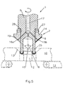
- the figures show a countersinking tool 1 for the production of conical recesses 13 on cylindrical bores 12 in Glass panes 10.
- a glass sheet 10 is located on a below of the countersink tool 1 located support 11 and is held there properly while the countersink tool 1 rotating about the (here) vertical axis of rotation the glass sheet 10 is lowered.
- a portion of the bore 12 remains straight cylindrical, while the reduction 13 executed as so-called depth reduction becomes. These are to be understood as subsidence, their insertion depth in the glass sheet 10 is significantly larger than it alone necessary for a deburring of the cylindrical bore 12 would.
- Such countersinking tool has a tool neck 6, the end in the tool holder of a drive spindle a machine tool 4 is clamped against rotation. On the Drive motor 3, the work spindle 2 is rotated. This rotational movement is optionally via a suitable Coupling end as a rotary motion in the tool neck 6 introduced there, where the drive end 5 is marked.
- the tool neck 6 has a tool head 7, which is equipped with a conical head angle 8 is.
- the tool head 7 has a conical inclined surface, where the abrasive pad 9 is attached. through This abrasive pad 9 is at a corresponding feed of the Countersink tool 1 in the direction of the glass pane 10, the depth reduction 13 central and concentric with the straight cylindrical Bore 12 introduced from one side.
- coolant supply 26 is effected by a Axial channel, which the tool neck 6 to the tool head. 7 interspersed and there in a channel system 16a, b, c, d passes, which opens in the region of the abrasive pad 9 on the tool head.
- the axial inflow passage 17 passes through the tool neck central to the axis of rotation, so that the coolant supply 26 is constantly communicating with the abrasive coating.
- the plastic spacer 14 follows in principle the head shape, which is defined by the apex 15 and has corresponding rotary drivers over which it rotatably connected to the drive spindle 2 is connected.
- a peripheral screw 27 in the embodiments according to. Fig.1, 3 and 5, by means of which the plastic intermediate piece 14 on the head side is posted on the tool neck 6.
- the circumferential screw connection 27 sits with a thread in a corresponding Tapped hole of the plastic spacer 14 and engages with a tapered pointed screw head corresponding recesses at the lower end of the tool neck 6 positively, so that the drive torque of the drive motor 3 directly into the plastic spacer 14th can be initiated.
- the rotary driver realized by a possible circumferential adhesive joint 28, between the plastic spacer 14 and the Pads of the tool neck is formed.
- the plastic spacer 14 therefore forms a rotationally symmetrical solid component, which is abrasive coating side the conical head shape of the countersink tool and which Tool side of the associated rotationally symmetric Training the straight-cylindrical tool neck follows.
- the material accumulation of the plastic intermediate piece 14 for the consumption of periodically recurring Forces and moments are used, which may be by the natural vibration behavior of the entire arrangement between Adjust machine tool 4 and workpiece 10.
- the plastic spacer 14 with respect the force acting in the direction of the cone tip 15 feed forces pressure resistant and also has good internal damping properties on.
- At least the plastic spacer 14 is such pressure resistant, that under the given feed forces during manufacture the depth reduction of the abrasive coating 9 substantially only subjected to compressive forces and therefore no elastic Deformations of the plastic spacer in the active area Must follow grinding zone.
- the figures show plastic spacers 14, which are interspersed by channels 10 and 16a to d. This is necessary if you want a communicating flow connection between the abrasive coating 9 and the axial inflow channel 26 create the active grinding zone always and continuously to supply with cooling liquid.
- the axial opens Inflow channel 14 additionally in a central distribution space 18, from which the radial channels 16a start up to 16d into the corresponding outlet openings in the Continue with abrasive coating 9.
- FIG. 2 shows a segmentation of the abrasive coating 9 in (here) four equally sized ring segments, which from respective recess grooves 19 are interrupted.
- the recessed grooves 19 open the respective radial Channels 16a to d, so that the cooling liquid of the head shape following the plastic spacer 14 over the entire can distribute active grinding zone.
- recessed grooves 19 are in the direction of the countersinking tool 1 limited by the material of the plastic spacer and through the adjacent walls of each the conical head of the plastic spacer 14 applied and mutually adjacent ring segments of Abrasive coating 9.
- the figures show countersink tools with head angles, which are smaller than 180 ° and larger than 0 °.
- the head angle is approximately 90 °.
- head angle 8 which clearly has no face plates with a Angle of 180 ° and no straight-cylindrical discs are at an angle of 0 °.
- FIG. 1 shows an exemplary embodiment which the plastic spacer 14 the tool head. 7 forms and centered on the front end of the tool neck. 6 is scheduled.
- the centering consists of a pairing of central Projection 20 and associated central recess 21st on the tool head or tool neck. It is the Depth 23 of the projection 20 is less than the depth 24 of the recess 21, so that the central distribution chamber 18 also at completely deep set intermediate piece 14 is formed automatically.
- the related distribution channels 16a to 16d can consequently mounted alone in the plastic spacer 14 be because the immersion depth 22 between projection 20 and recess 21 is less than the available depth 24 of the recess 21st
- the immersion depth 22 of the projection 20 is in the recess 21 is limited by a depth stop so that the central distribution space 18 is created, which on both sides of the abrasive pad 9 as well as on the side of the tool neck 6 communicates with a channel system for cooling fluid.
- the depth stop is by a Ring paragraph formed on the tool neck 6, against which the annular end face of the plastic intermediate piece 14 under Tightening of the compression fitting 27 held pressure-resistant.
- the channel system 16a to 16d on the side of the abrasive coating 9 in at least two to lead to different radii. This requirement is made possible by the basically conical tool head. All distribution channels 16a to 16d should be in the range the recessed grooves 19 on the top surface of the plastic spacer 14 lead.
- FIGS. 3 and 4 show a development, in which both the plastic spacer 14 as also the tool neck 6 made of plastic.
- Fig.3 consists of Tool neck 6 made of a plastic other than the plastic adapter 14.
- the attachment between plastic spacer 14 and tool neck 6 corresponds to the construction according to Fig.1.
- plastic spacer 14 the entire countersink tool one-piece and one-piece made of plastic and can therefore be referred to as plastic spacer 14 become.
- FIG. 5 shows an exemplary embodiment, in which the tool neck 6, the entire plastic spacer 14 in the direction of the apex 15 interspersed and this towered over a piece.
- the tool neck 6 forms a straight ring cylinder, which at the end face an abrasive Covering z. B. is sintered. Do you do that? Tool towards a glass plate 10, so will first once the straight cylindrical hole drilled, which subsequently from the subordinate countersink tool with the countersink is provided.
- the coating on the Glued on plastic spacer In all embodiments, the coating on the Glued on plastic spacer. To this end Two-component or hot-melt adhesives could be used.
Landscapes
- Engineering & Computer Science (AREA)
- Mechanical Engineering (AREA)
- Chemical & Material Sciences (AREA)
- Ceramic Engineering (AREA)
- Inorganic Chemistry (AREA)
- Polishing Bodies And Polishing Tools (AREA)
- Processing Of Stones Or Stones Resemblance Materials (AREA)
Description
- relativ große auskragende Längen zwischen der Werkzeugspindel und dem Werkzeugkopf,
- große Hebellängen zwischen Spindelachse und Vorschubverfahrschlitten,
- zu geringe Antriebsleistungen der Werkzeugspindel,
- zu geringe Steifigkeit des Maschinengestells.
- Fig.1
- ein erstes Ausführungsbeispiel der Erfindung,
- Fig.1a
- Darstellung der Kopfwinkelgeometrie,
- Fig.2
- Aufsicht auf die Spitze eines Senkerwerkzeugs gemäß Fig.1,
- Fig.3
- ein Ausführungsbeispiel der Erfindung mit einem zweiteiligen Senkerwerkzeug aus Kunststoffmaterialien,
- Fig.4
- ein Ausführungsbeispiel der Erfindung mit einem einstückigen Senkerwerkzeug aus Kunststoff,
- Fig.5
- ein Ausführungsbeispiel der Erfindung mit vorgeordnetem Bohrabschnitt.
Claims (15)
- Senkerwerkzeug (1) zur Herstellung von konischen Ansenkungen (13) an zylindrischen Bohrungen (12) in Glasscheiben (10) mit einem endseitig in die Werkzeugaufnahme einer Werkzeugmaschine (4) einzuspannenden Werkzeughals (6), der anderenends einen daran befindlichen Werkzeugkopf (7) mit kegelförmigem Kopfwinkel (8) aufweist, an dessen Schrägfläche der Schleifbelag (9) angebracht ist, dadurch gekennzeichnet, daß der Schleifbelag (9) über ein Kunststoffzwischenstück (14) drehfest mit der Antriebsspindel (2) verbunden ist und daß das Kunststoffzwischenstück (14) bezüglich der in Richtung zur Kegelspitze (15) wirkenden Vorschubkräfte druckfest ist und zusätzlich gute innere Dämpfungseigenschaften aufweist, daß das Kunststoffzwischenstück (14) von Kanälen (17, 16a bis d) durchsetzt ist, die eine kommunizierende Strömungsverbindung zwischen dem Schleifbelag (9) und einem axialen Zuströmkanal (26) schaffen, welcher mit Kühlflüssigkeit versorgt wird, daß die radialen Vertiefungen Vertiefungsnuten (19) sind, welche den Schleifbelag (9) in Richtung zum Kunststoffzwischenstück (14) durchsetzen, und daß die Verteilkanäle (16a bis d) in radialen Vertiefungen des Schleifbelags (9) enden, wobei das Kunststoffzwischenstück 14 dabei prinzipiell der Kopfform folgt, welche durch die Kegelspitze 15 festgelegt ist und entsprechende Drehmitnehmer aufweist, über welche es drehfest mit der Antriebsspindel 2 verbunden ist.
- Senkerwerkzeug nach Anspruch 1 dadurch gekennzeichnet, daß die Kanäle (16a bis d,17) mit einem zentralen Verteilerraum (18) kommunizieren und sich von dort radial bis zum Schleifbelag (9) fortsetzen.
- Senkerwerkzeug nach Anspruch 1 oder 2, dadurch gekennzeichnet, daß der Kopfwinkel (8) kleiner als 180° und größer als 0° ist.
- Senkerwerkzeug nach Anspruch 3, dadurch gekennzeichnet, daß der Kopfwinkel größer als 110° und kleiner als 130° ist.
- Senkerwerkzeug nach einem der Ansprüche 1 bis 4, dadurch gekennzeichnet, daß das Kunststoffzwischenstück (14) den Werkzeugkopf (7) bildet und zentriert an das vordere Ende des Werkzeughalses (6) angesetzt ist.
- Senkerwerkzeug nach Anspruch 5, dadurch gekennzeichnet, daß die Zentrierung aus einer Paarung von zentralem Vorsprung (20) und zugehöriger zentraler Ausnehmung (21) am Werkzeugkopf (7) bzw. Werkzeughals (6) ist.
- Senkerwerkzeug nach Anspruch 6, dadurch gekennzeichnet, daß die Eintauchtiefe (22) des Vorsprungs (20) in der Ausnehmung (21) durch einen Tiefenanschlag so begrenzt ist, daß ein zentraler Verteilerraum (18) entsteht, der sowohl auf Seiten des Schleifbelags (9) als auch auf Seiten des Werkzeughalses (6) mit je einem Kanalsystem (17;16a bis d) für Kühlflüssigkeit kommuniziert.
- Senkerwerkzeug nach Anspruch 7, dadurch gekennzeichnet, daß das Kanalsystem (16a bis d) auf Seiten des Schleifbelags (9) in wenigstens zwei unterschiedlichen Radien auf die Bearbeitungsstelle mündet.
- Senkerwerkzeug nach einem der Ansprüche 1 bis 4, dadurch gekennzeichnet, daß das Kunststoffzwischenstück (14) und ebenso der Werkzeughals (6) aus Kunststoff bestehen.
- Senkerwerkzeug nach Anspruch 9, dadurch gekennzeichnet, daß Kunststoffzwischenstück (14) und Werkzeughals (6) zweiteilig ausgebildet und daß beide Bestandteile aneinander angesetzt sind.
- Senkerwerkzeug nach einem der Ansprüche 1 bis 10, dadurch gekennzeichnet, daß zwischen den Anschlußflächen des Kunststoffzwischenstücks (14) und den benachbarten Werkzeugteilen eine Klebefuge (28) ausgebildet ist.
- Senkerwerkzeug nach Anspruch 9, dadurch gekennzeichnet, daß Kunststoffzwischenstück (14) und Werkzeughals (6) einteilig und einstückig ausgebildet sind.
- Senkerwerkzeug nach einem der Ansprüche 1 bis 12, dadurch gekennzeichnet, daß dem Kunststoffzwischenstück (14) ein Bohrwerkzeug (25) vorgeordnet ist, welches der Herstellung der zylindrischen Bohrung dient.
- Senkerwerkzeug nach einem der Ansprüche 1 bis 13, dadurch gekennzeichnet, daß der Schleifbelag auf das Kunststoffzwischenstück (14) aufgeklebt ist.
- Senkerwerkzeug nach Anspruch 14, dadurch gekennzeichnet, daß der Schleifbelag gesintert ist.
Applications Claiming Priority (2)
| Application Number | Priority Date | Filing Date | Title |
|---|---|---|---|
| DE10032036 | 2000-07-05 | ||
| DE10032036A DE10032036A1 (de) | 2000-07-05 | 2000-07-05 | Senkerwerkzeug |
Publications (3)
| Publication Number | Publication Date |
|---|---|
| EP1170091A2 EP1170091A2 (de) | 2002-01-09 |
| EP1170091A3 EP1170091A3 (de) | 2002-10-30 |
| EP1170091B1 true EP1170091B1 (de) | 2005-08-10 |
Family
ID=7647440
Family Applications (1)
| Application Number | Title | Priority Date | Filing Date |
|---|---|---|---|
| EP01114535A Expired - Lifetime EP1170091B1 (de) | 2000-07-05 | 2001-06-16 | Senkerwerkzeug |
Country Status (4)
| Country | Link |
|---|---|
| US (1) | US20020004362A1 (de) |
| EP (1) | EP1170091B1 (de) |
| DE (2) | DE10032036A1 (de) |
| ES (1) | ES2246963T3 (de) |
Families Citing this family (19)
| Publication number | Priority date | Publication date | Assignee | Title |
|---|---|---|---|---|
| AT5265U1 (de) * | 2001-07-27 | 2002-05-27 | Schraml Glastechnik Gmbh | Diamant-hohlbohrer |
| DE20212640U1 (de) | 2002-08-09 | 2002-10-31 | Bohle AG, 42781 Haan | Senkwerkzeug zum Säumen von Bohrungen in Glas sowie Schleifhut |
| US7125328B1 (en) | 2005-09-10 | 2006-10-24 | Michael Hacikyan | Glass grinding bit |
| JP4735381B2 (ja) * | 2006-04-05 | 2011-07-27 | 株式会社デンソー | 研削装置および研削方法 |
| DE102007034140B4 (de) * | 2006-11-30 | 2011-05-12 | Gunther Schwarz Gmbh | Instandsetzungswerkzeug |
| DE202006018176U1 (de) * | 2006-11-30 | 2007-03-29 | Gunther Schwarz Gmbh | Instandsetzungswerkzeug |
| FR2946908B1 (fr) * | 2009-06-18 | 2011-07-15 | Peugeot Citroen Automobiles Sa | Procede et outil pour obtenir une culasse de cylindre finie |
| DE102011076649B4 (de) * | 2011-05-27 | 2026-05-07 | Schaeffler Technologies AG & Co. KG | Schleifstift zum Schleifen einer Innenoberfläche eines Hohlraumes |
| CN106573395B (zh) * | 2014-08-26 | 2021-02-05 | 3M创新有限公司 | 阻尼磨料切割器 |
| WO2016109734A1 (en) | 2014-12-30 | 2016-07-07 | Saint-Gobain Abrasives, Inc. | Abrasive tools and methods for forming same |
| AU2016381202B2 (en) | 2015-12-30 | 2019-03-14 | Saint-Gobain Abrasifs | Abrasive tools and methods for forming same |
| WO2017147035A1 (en) * | 2016-02-26 | 2017-08-31 | 3M Innovative Properties Company | Damped abrasive article |
| WO2018183724A1 (en) * | 2017-03-31 | 2018-10-04 | Saint-Gobain Abrasives, Inc. | Grinding wheel assembly |
| US10603764B2 (en) * | 2017-05-26 | 2020-03-31 | General Electric Company | Burnishing tool and method of manufacturing the same |
| CN107322469A (zh) * | 2017-08-30 | 2017-11-07 | 苏州安洁科技股份有限公司 | 一种带有抛光功能的玻璃磨头 |
| CN107837879A (zh) * | 2017-10-31 | 2018-03-27 | 王明法 | 一种粉末涂料筛选研磨装置 |
| WO2020081906A1 (en) | 2018-10-19 | 2020-04-23 | Saint-Gobain Abrasives, Inc. | Grinding wheel assembly |
| CN109434611B (zh) * | 2018-12-26 | 2020-03-27 | 贰陆光学(苏州)有限公司 | 镜片倒角装置 |
| CN114227430B (zh) * | 2021-11-26 | 2022-10-11 | 绍兴市舜海铜材有限公司 | 一种金属管件自动去毛刺装置 |
Family Cites Families (4)
| Publication number | Priority date | Publication date | Assignee | Title |
|---|---|---|---|---|
| BE718357A (de) * | 1968-07-19 | 1968-12-31 | ||
| DE4024399A1 (de) * | 1990-08-01 | 1992-02-06 | Hilti Ag | Bohrwerkzeug |
| US5993297A (en) * | 1994-09-06 | 1999-11-30 | Makino Inc. | Superabrasive grinding wheel with integral coolant passage |
| JP2001527469A (ja) * | 1997-06-17 | 2001-12-25 | ノートン カンパニー | 研磨工具の耐摩耗性を改良する方法 |
-
2000
- 2000-07-05 DE DE10032036A patent/DE10032036A1/de not_active Withdrawn
-
2001
- 2001-06-16 EP EP01114535A patent/EP1170091B1/de not_active Expired - Lifetime
- 2001-06-16 DE DE50107018T patent/DE50107018D1/de not_active Expired - Lifetime
- 2001-06-16 ES ES01114535T patent/ES2246963T3/es not_active Expired - Lifetime
- 2001-06-29 US US09/896,668 patent/US20020004362A1/en not_active Abandoned
Also Published As
| Publication number | Publication date |
|---|---|
| DE10032036A1 (de) | 2002-01-17 |
| US20020004362A1 (en) | 2002-01-10 |
| ES2246963T3 (es) | 2006-03-01 |
| EP1170091A2 (de) | 2002-01-09 |
| EP1170091A3 (de) | 2002-10-30 |
| DE50107018D1 (de) | 2005-09-15 |
Similar Documents
| Publication | Publication Date | Title |
|---|---|---|
| EP1170091A2 (de) | Senkerwerkzeug | |
| DE102006016290C5 (de) | Mehrteiliges Schaftwerkzeug, insbesondere Feinbearbeitungswerkzeug | |
| EP1669148B1 (de) | Werkzeugeinheit zur ultraschallunterstützten rotativen Bearbeitung | |
| EP1265723B1 (de) | Maschinenreibahle und reibkopf für eine maschinenreibahle | |
| DE3610016C2 (de) | ||
| DE102009048010B3 (de) | Werkzeuginterface | |
| EP2855059B1 (de) | Modularer werkzeughalter | |
| WO1997017153A1 (de) | Bohrwerkzeug mit auswechselbarer spitze | |
| EP2509745B1 (de) | Bausatz zum nachrüsten einer elektrodenschleifvorrichtung und elektrodenschleifvorrichtung | |
| EP3837076B1 (de) | Faswerkzeug | |
| EP1768808B1 (de) | Werkzeugadapter | |
| DE20204848U1 (de) | Auswechselbare Bohrerspitze und Bohrwerkzeuganordnung | |
| EP0307550A1 (de) | Schwenkbare Werkzeugaufnahme für Roboter | |
| EP2448705B1 (de) | Werkzeug zur bearbeitung oder herstellung einer bohrung mit einer senkung | |
| EP1612018B1 (de) | Werkzeug zur Bearbeitung eines mineralischen Untergrundes | |
| DE102006007787A1 (de) | Vorrichtung und Verfahren zum spanabhebenden Herstellen einer kalottenförmigen Ausnehmung in einem Werkstück | |
| DE102004062443A1 (de) | Honwerkzeuganordnung sowie Honstange und Honwerkzeug einer Honwerkzeuganordnung | |
| EP4338874A2 (de) | Fräswerkzeug, schneidenträger und werkzeugkopf | |
| EP0981421B1 (de) | Schleifscheibe zur bearbeitung von metallkreissägeblättern | |
| EP0850715B1 (de) | Wendeschneidwerkzeug | |
| EP1259350A1 (de) | Reibwerkzeug mit führungsschaft | |
| DE4008350A1 (de) | Schaftwerkzeug fuer die innen- und/oder aussenbearbeitung von werkstueckoberflaechen | |
| EP1740338A1 (de) | Räumwerkzeug und verfahren zur spanenden bearbeitung von bohrungsoberflächen | |
| CH716180A2 (de) | Vorrichtung und Verfahren zur mechanischen Finishbearbeitung einer Oberfläche eines Werkstückes. | |
| AT14283U1 (de) | Schneidwerkzeug |
Legal Events
| Date | Code | Title | Description |
|---|---|---|---|
| PUAI | Public reference made under article 153(3) epc to a published international application that has entered the european phase |
Free format text: ORIGINAL CODE: 0009012 |
|
| AK | Designated contracting states |
Kind code of ref document: A2 Designated state(s): AT BE CH CY DE DK ES FI FR GB GR IE IT LI LU MC NL PT SE TR |
|
| AX | Request for extension of the european patent |
Free format text: AL;LT;LV;MK;RO;SI |
|
| PUAL | Search report despatched |
Free format text: ORIGINAL CODE: 0009013 |
|
| AK | Designated contracting states |
Kind code of ref document: A3 Designated state(s): AT BE CH CY DE DK ES FI FR GB GR IE IT LI LU MC NL PT SE TR |
|
| AX | Request for extension of the european patent |
Free format text: AL;LT;LV;MK;RO;SI |
|
| 17P | Request for examination filed |
Effective date: 20030319 |
|
| AKX | Designation fees paid |
Designated state(s): BE DE ES FR GB IT |
|
| 17Q | First examination report despatched |
Effective date: 20040628 |
|
| GRAP | Despatch of communication of intention to grant a patent |
Free format text: ORIGINAL CODE: EPIDOSNIGR1 |
|
| GRAS | Grant fee paid |
Free format text: ORIGINAL CODE: EPIDOSNIGR3 |
|
| GRAA | (expected) grant |
Free format text: ORIGINAL CODE: 0009210 |
|
| AK | Designated contracting states |
Kind code of ref document: B1 Designated state(s): BE DE ES FR GB IT |
|
| REG | Reference to a national code |
Ref country code: GB Ref legal event code: FG4D Free format text: NOT ENGLISH |
|
| GBT | Gb: translation of ep patent filed (gb section 77(6)(a)/1977) |
Effective date: 20050810 |
|
| REF | Corresponds to: |
Ref document number: 50107018 Country of ref document: DE Date of ref document: 20050915 Kind code of ref document: P |
|
| REG | Reference to a national code |
Ref country code: ES Ref legal event code: FG2A Ref document number: 2246963 Country of ref document: ES Kind code of ref document: T3 |
|
| ET | Fr: translation filed | ||
| PLBE | No opposition filed within time limit |
Free format text: ORIGINAL CODE: 0009261 |
|
| STAA | Information on the status of an ep patent application or granted ep patent |
Free format text: STATUS: NO OPPOSITION FILED WITHIN TIME LIMIT |
|
| 26N | No opposition filed |
Effective date: 20060511 |
|
| REG | Reference to a national code |
Ref country code: DE Ref legal event code: R082 Ref document number: 50107018 Country of ref document: DE |
|
| REG | Reference to a national code |
Ref country code: FR Ref legal event code: PLFP Year of fee payment: 16 |
|
| REG | Reference to a national code |
Ref country code: FR Ref legal event code: PLFP Year of fee payment: 17 |
|
| REG | Reference to a national code |
Ref country code: FR Ref legal event code: PLFP Year of fee payment: 18 |
|
| PGFP | Annual fee paid to national office [announced via postgrant information from national office to epo] |
Ref country code: DE Payment date: 20180605 Year of fee payment: 18 |
|
| PGFP | Annual fee paid to national office [announced via postgrant information from national office to epo] |
Ref country code: BE Payment date: 20180417 Year of fee payment: 18 Ref country code: FR Payment date: 20180511 Year of fee payment: 18 |
|
| PGFP | Annual fee paid to national office [announced via postgrant information from national office to epo] |
Ref country code: ES Payment date: 20180702 Year of fee payment: 18 Ref country code: IT Payment date: 20180625 Year of fee payment: 18 Ref country code: GB Payment date: 20180403 Year of fee payment: 18 |
|
| REG | Reference to a national code |
Ref country code: DE Ref legal event code: R119 Ref document number: 50107018 Country of ref document: DE |
|
| GBPC | Gb: european patent ceased through non-payment of renewal fee |
Effective date: 20190616 |
|
| REG | Reference to a national code |
Ref country code: BE Ref legal event code: MM Effective date: 20190630 |
|
| PG25 | Lapsed in a contracting state [announced via postgrant information from national office to epo] |
Ref country code: IT Free format text: LAPSE BECAUSE OF NON-PAYMENT OF DUE FEES Effective date: 20190616 Ref country code: GB Free format text: LAPSE BECAUSE OF NON-PAYMENT OF DUE FEES Effective date: 20190616 Ref country code: DE Free format text: LAPSE BECAUSE OF NON-PAYMENT OF DUE FEES Effective date: 20200101 |
|
| PG25 | Lapsed in a contracting state [announced via postgrant information from national office to epo] |
Ref country code: BE Free format text: LAPSE BECAUSE OF NON-PAYMENT OF DUE FEES Effective date: 20190630 |
|
| PG25 | Lapsed in a contracting state [announced via postgrant information from national office to epo] |
Ref country code: FR Free format text: LAPSE BECAUSE OF NON-PAYMENT OF DUE FEES Effective date: 20190630 |
|
| REG | Reference to a national code |
Ref country code: ES Ref legal event code: FD2A Effective date: 20201028 |
|
| PG25 | Lapsed in a contracting state [announced via postgrant information from national office to epo] |
Ref country code: ES Free format text: LAPSE BECAUSE OF NON-PAYMENT OF DUE FEES Effective date: 20190617 |