EP1168249B1 - Verfahren und Vorrichtung zur dreidimensionalen Rekonstruktion von Röntgenbilder mit niedriger Strahlungsdosis - Google Patents
Verfahren und Vorrichtung zur dreidimensionalen Rekonstruktion von Röntgenbilder mit niedriger Strahlungsdosis Download PDFInfo
- Publication number
- EP1168249B1 EP1168249B1 EP01401511A EP01401511A EP1168249B1 EP 1168249 B1 EP1168249 B1 EP 1168249B1 EP 01401511 A EP01401511 A EP 01401511A EP 01401511 A EP01401511 A EP 01401511A EP 1168249 B1 EP1168249 B1 EP 1168249B1
- Authority
- EP
- European Patent Office
- Prior art keywords
- generic model
- marks
- model
- check
- images
- Prior art date
- Legal status (The legal status is an assumption and is not a legal conclusion. Google has not performed a legal analysis and makes no representation as to the accuracy of the status listed.)
- Expired - Lifetime
Links
Images

Classifications
-
- A—HUMAN NECESSITIES
- A61—MEDICAL OR VETERINARY SCIENCE; HYGIENE
- A61B—DIAGNOSIS; SURGERY; IDENTIFICATION
- A61B6/00—Apparatus for radiation diagnosis, e.g. combined with radiation therapy equipment
- A61B6/44—Constructional features of apparatus for radiation diagnosis
- A61B6/4429—Constructional features of apparatus for radiation diagnosis related to the mounting of source units and detector units
- A61B6/4435—Constructional features of apparatus for radiation diagnosis related to the mounting of source units and detector units the source unit and the detector unit being coupled by a rigid structure
- A61B6/4441—Constructional features of apparatus for radiation diagnosis related to the mounting of source units and detector units the source unit and the detector unit being coupled by a rigid structure the rigid structure being a C-arm or U-arm
-
- A—HUMAN NECESSITIES
- A61—MEDICAL OR VETERINARY SCIENCE; HYGIENE
- A61B—DIAGNOSIS; SURGERY; IDENTIFICATION
- A61B6/00—Apparatus for radiation diagnosis, e.g. combined with radiation therapy equipment
- A61B6/06—Diaphragms
-
- A—HUMAN NECESSITIES
- A61—MEDICAL OR VETERINARY SCIENCE; HYGIENE
- A61B—DIAGNOSIS; SURGERY; IDENTIFICATION
- A61B6/00—Apparatus for radiation diagnosis, e.g. combined with radiation therapy equipment
- A61B6/50—Clinical applications
- A61B6/505—Clinical applications involving diagnosis of bone
-
- G—PHYSICS
- G06—COMPUTING; CALCULATING OR COUNTING
- G06T—IMAGE DATA PROCESSING OR GENERATION, IN GENERAL
- G06T7/00—Image analysis
- G06T7/50—Depth or shape recovery
- G06T7/55—Depth or shape recovery from multiple images
- G06T7/564—Depth or shape recovery from multiple images from contours
-
- G—PHYSICS
- G06—COMPUTING; CALCULATING OR COUNTING
- G06T—IMAGE DATA PROCESSING OR GENERATION, IN GENERAL
- G06T2207/00—Indexing scheme for image analysis or image enhancement
- G06T2207/10—Image acquisition modality
- G06T2207/10072—Tomographic images
- G06T2207/10112—Digital tomosynthesis [DTS]
-
- G—PHYSICS
- G06—COMPUTING; CALCULATING OR COUNTING
- G06T—IMAGE DATA PROCESSING OR GENERATION, IN GENERAL
- G06T2207/00—Indexing scheme for image analysis or image enhancement
- G06T2207/10—Image acquisition modality
- G06T2207/10116—X-ray image
-
- G—PHYSICS
- G06—COMPUTING; CALCULATING OR COUNTING
- G06T—IMAGE DATA PROCESSING OR GENERATION, IN GENERAL
- G06T2207/00—Indexing scheme for image analysis or image enhancement
- G06T2207/30—Subject of image; Context of image processing
- G06T2207/30004—Biomedical image processing
Definitions
- the present invention relates to radiographic imaging methods and devices for three-dimensional low dose radiation reconstruction.
- step (d) is a kriging step consisting of interpolation / extrapolation of the generic model of the object to be observed, which gives estimated positions of a large number of references of the model to three dimensions of the object to be observed according to the measured coordinates of the stereo-corresponding control marks and according to the geometry of the generic model. This stage of kriging has been described in particular by Trochu ("A contouring program based on dual kriging interpolation", Comput Eng 9, pp 160-177, 1993 ).
- the present invention is intended to overcome these disadvantages.
- a method of the kind in question is characterized in that during step (a), the two radiographic images are taken simultaneously, by scanning, by moving in synchronism, in the same direction. translation direction not parallel to the shooting directions, at least one radioactive source emitting two beams of ionizing radiation respectively in the two directions of shooting.
- the field of observation mentioned above may include the spine, the pelvis, or the knee of a patient, or more generally be constituted by all or part of the skeleton of the patient.
- the objects to be observed may consist in particular of the bones of the patient included in the field of view and the duration of the shooting operations.
- This precision is obtained thanks to the simultaneity of the two shots, and thanks to the scanning shot which improves the precision in the direction of the scan notably for the extended fields of observation.
- the figure 1 represents a radiographic device 1 for the three-dimensional reconstruction, comprising a mobile frame 2 movable vertically motorized on vertical guides 3, in a direction of translation 3a.
- This frame surrounds an observation field 4 in which a patient P can stand. It is thus possible to observe the position of the bones of the skeleton of this patient while standing, which is essential in particular for patients with scoliosis.
- the mobile frame 2 carries a first radioactive source 5 and a first detector 6 which is disposed facing the source 5 beyond the field 4, and which comprises a horizontal line 6a of detection cells.
- the detector 6 may for example be a gaseous detector sensitive to low doses of radiation, for example as described in the document FR-A-2 749 402 or FR-A-2,754,068 .
- other types of detectors, gaseous or otherwise, could possibly be used in the context of the present invention.
- the radioactive source 5 is adapted to emit ionizing rays, in particular X-rays, in an anteroposterior direction of shooting with respect to the patient P, by passing through a horizontal slit 8 formed in a reticle 9 such as a plate metal, to generate a horizontal beam 10 of ionizing radiation in the field of view 4.
- the mobile frame 2 also carries a second radioactive source 11 similar to the source 5 and a second detector 12 similar to the detector 6, which is arranged facing the source 11 beyond the field 4, and which comprises a horizontal line 12a of detection cells.
- the radioactive source 11 is adapted to emit ionizing rays, in a lateral direction of shooting 13 relative to the patient P, through a horizontal slot 14 formed in a reticle 15 such as a metal plate, to generate a horizontal beam 16 of ionizing radiation in the field of view 4.
- radioactive sources and the detectors could, if necessary, be in a number greater than 2, and that the directions of shooting of these different radioactive sources could if need be not perpendicular to each other or horizontal.
- the microcomputer 17 can also be connected to the motorized drive means (not shown) contained in the guides 3 and the sources 5, 11, so as to control the vertical displacement of the frame 2 and the emission of ionizing radiation.
- the device that has just been described operates as follows.
- two radiographic images of the patient P are first taken, by scanning the field of observation 4 by the beams 1C, 16 of ionizing radiation over the height corresponding to the patient's zone to be observed.
- the frame is preferably movable over a height of at least 70 cm, or even greater than 1 m).
- two digital radiographic images are recorded in the memory of the microcomputer 17, for example anteroposterior and lateral respectively of the examined part of the patient, which images can be viewed on the screen 19 of the microcomputer. .
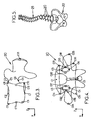
- Each of these images generally comprises several predetermined objects to be examined, for example vertebrae 20 such as that shown schematically on the figure 2 .
- the microcomputer 17 has in memory a three-dimensional generic model which corresponds to an average form of the object in question, which generic model is prepared in advance by statistical methods by analyzing a lot of similar objects.
- the practitioner may, for example, indicate to the microcomputer, in particular by means of the keyboard 18 or the mouse, the type of each object to be examined visible on the microcomputer 17. said images, so that the microcomputer 17 determines the generic model corresponding to this object.
- the generic models used could also be constituted by models previously made by medical imaging on the patient: in this case, the method according to the invention can allow for example to follow the subsequent evolution of the patient by simpler means , less expensive and emitting less radiation than conventional three-dimensional imaging means.
- These coordinates can be expressed for example in a local repository X, Y, Z.
- the Z axis corresponds to the "axial" direction of the spine
- the X axis is determined so as to define with the Z axis the anteroposterior plane of the vertebra 20, the Y axis being perpendicular to the X, Z axes mentioned above.
- the origin O of the reference frame X, Y, Z is disposed in the middle of the two axial end faces of the main "tubular" portion of the vertebra, the origin O being furthermore positioned so that the Z axis crosses the upper axial face of the main part of the vertebra at a marker C1 such that the distance from this marker C1 to the front end C7 of said axial face is equal to about 2/3 of the total distance between the front ends C7 and C8 rear of the anteroposterior section of said upper axial face.
- the practitioner identifies these different control marks for each object to be examined (for example the vertebrae and the pelvis) on each radiographic image, for example by "marking" these markers on the screen 19 by selection by means of the mouse and / or of the keyboard.
- the two images are calibrated, so as to accurately measure the position of each marker of these images in a common repository.
- the position of the corresponding stereo control marks C1-C6 is directly calculated from the measurement of the position of these points on the two images.
- x i is a predetermined stiffness coefficient of the fictitious spring of index i
- x i, 0 is the length of the notional spring of index i in the undeformed generic model
- x i is the notional spring length of index i in the deformed generic model.
- the three-dimensional shape of a model representing the vertebra 20 of the patient is calculated, the calculated model being obtained by deforming the generic model so as to maintain the coincidence of the control points of the deformed generic model with the previously determined spatial position. control points and so that said calculated model follows a form as close as possible to an isometry of the generic model, this time working on all generic model points.
- obtaining the three-dimensional model of each object to be examined can be obtained by the known method of kriging ("krigirg").
- the microcomputer 17 can assemble all the three-dimensional models of the different objects to be examined, depending on the position of these different models in an absolute reference common to all. these objects, so as to obtain a three-dimensional model comprising, for example, the entire spine 21 of the patient and the pelvis 22 of this patient, as shown in FIG. figure 5 .
- this three-dimensional model can be presented on the screen 19 of the microcomputer, or printed, under the desired viewing angle.
- This overall model can also be set in motion on the screen according to the practitioner's commands.
- the practitioner thus has an effective examination tool that can be used for imaging any part, in particular bone or cartilaginous parts of the human or animal body, and useful in particular for the diagnosis of scoliosis. or for pre- or post-operative follow-up during surgical procedures.
- the radiographic device 1 could, if necessary, be adapted for examination of a lying patient, which may be indispensable in the field of trauma.
- the patient P would be lying on a support table, the ionizing radiation beams 10, 16 would each be in a vertical plane, and the sources 5, 11 would move horizontally with the detectors 6, 12.
- the radiographic device 1 can also be used in two-dimensional radiography, in addition to its use in three-dimensional imaging.
Claims (16)
- Röntgenbildgebungsverfahren zur dreidimensionalen Rekonstruktion mit geringer Bestrahlungsdosis, das dazu geeignet ist, ein dreidimensionales Modell mindestens eines vorbestimmten Objekts (20) zu berechnen, das in einem Betrachtungsfeld (4) betrachtet werden soll, wobei dieses Verfahren die folgenden Schritte umfasst:(a)Aufnehmen mindestens zwei zweidimensionaler Röntgenbilder des Betrachtungsfelds, jeweils gemäß zwei nicht parallelen Bildaufnahmerichtungen (7, 13),(b)Markieren von Kontrollmarken (C1-C25) auf jedem Röntgenbild, die zum zu betrachtenden Objekt gehören,(c)Bestimmen einer geometrischen Position jeder Kontrollmarke in einem dreidimensionalen Bezugssystem,(d)Berechnen der dreidimensionalen Form eines das Objekt darstellenden Modells ausgehend von einem dem Objekt entsprechenden vorbestimmten generischen Modell, wobei dieses generische Modell Marken aufweist, die den auf den Röntgenbildern identifizierten Kontrollmarken entsprechen, wobei das berechnete Modell durch Verformung des generischen Modells derart erhalten wird, dass das berechnete Modell einer einer Isometrie des generischen Modells nächstmöglichen Form folgt, unter Beibehaltung der Koinzidenz der Marken des verformten generischen Modells mit den im Schritt (c) rekonstruierten Kontrollmarken,dadurch gekennzeichnet, dass während des Schritts (a) die zwei Röntgenbilder gleichzeitig durch Abtasten aufgenommen werden, indem synchron in der gleichen Translationsrichtung (3a) nicht parallel zu den Bildaufnahmerichtungen mindestens eine radioaktive Quelle (5, 11) verschoben wird, die zwei Bündel ionisierender Strahlen (10, 16) in den zwei Bildaufnahmerichtungen (7, 13) emittiert.
- Verfahren nach Anspruch 1, bei dem:- während des Schritts (b) bestimmte der identifizierten Kontrollmarken, nicht stereo-korrespondierende Kontrollmarken genannt, nur in einem Bild sichtbar und identifiziert sind,- und während des Schritts (c) die geometrische Position jeder nicht stereo-korrespondierenden Kontrollmarke (C7-C25) im dreidimensionalen Bezugssystem ausgehend vom generischen Modell geschätzt wird, indem die nicht stereo-korrespondierenden Kontrollmarken des generischen Modells je auf einer Geraden verschoben werden, die:verbindet,. einerseits die radioaktive Quelle (5, 11), die Ausgangspunkt des Röntgenbilds ist, auf dem eine Projektion dieser nicht stereo-korrespondierenden Kontrollmarke sichtbar und identifizierbar ist,. und andererseits die Projektion dieser Marke auf dem Röntgenbild,
wobei die nicht stereo-korrespondierenden Kontrollmarken (C7-C25) so bis in jeweilige Positionen verschoben werden, die die globale Verformung des generischen Modells des zu betrachtenden Objekts minimieren. - Verfahren nach Anspruch 2, bei dem während des Schritts (c) der Wert der quadratischen Summe minimiert wird:
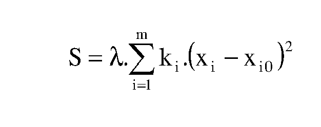
wobei λ ein konstanter Koeffizient, m eine ganze Anzahl fiktiver Federn, die jede Marke (C1-C25) des generischen Modells mit anderen Marken dieses Modells verbinden, ki ein vorbestimmter Steifheitswert der fiktiven Feder mit dem Index i, Xi0 die Länge der fiktiven Feder mit dem Index i im generischen Anfangsmodell und Xi die fiktive Federlänge mit dem Index i im verformten generischen Modell ist. - Verfahren nach einem der vorhergehenden Ansprüche, bei dem:- während des Schritts (b) mindestens bestimmte der identifizierbaren Kontrollmarken stereo-korrespondierende Kontrollmarken (C1-C6) sind, die auf den zwei Bildern sichtbar und identifiziert sind,- und während des Schritts (c) die geometrische Position der stereo-korrespondierenden Kontrollmarken (C1-C6) direkt ausgehend von Positionsmessungen der Projektionen dieser Marken auf die zwei Bilder berechnet wird.
- Verfahren nach Anspruch 1, bei dem während des Schritts (b) auf jedem Röntgenbild Umrisslinien markiert werden, die Grenzen des betrachteten Objekts und/oder Linien größerer optischer Dichte innerhalb der Grenzen entsprechen, wobei diese Umrisslinien Projektionen der Kontrollmarken auf die Röntgenbilder enthalten.
- Verfahren nach Anspruch 5, bei dem während des Schritts (c) Marken des generischen Modells entsprechend den Kontrollmarken bestimmt werden, wobei die Marken des generischen Modells Abschnitte des generischen Modells enthalten, die tangential bezüglich der von den radioaktiven Quellen stammenden und die Röntgenbilder erzeugt habenden Strahlen erscheinen.
- Verfahren nach Anspruch 6, bei dem der Schritt (c) die folgenden Teilschritte aufweist:(c1) Erzeugen eines neueingestellten generischen Modells durch Anpassen der Größe des generischen Modells und der Position dieses generischen Modells im Bezugssystem, damit die jeweiligen Projektionen des neueingestellten generischen Modells ausgehend von den zwei radioaktiven Quellen im Wesentlichen den zwei Röntgenbildern entsprechen,(c2) Auswählen der Marken des generischen Modells, dessen Projektionen auf mindestens eines der Röntgenbilder ausgehend von der entsprechenden radioaktiven Quelle den Umrisslinien am nächsten sind, die während des Schritts (b) markiert wurden,(c3) Definieren einer Hüllfläche, die von Strahlen geformt wird, welche von jeder radioaktiven Quelle (5, 11) stammen und die dazu beigetragen haben, die Umrisslinien der Röntgenbilder zu erzeugen,(c4) Bestimmen bestimmter Marken des neueingestellten generischen Modells entsprechend Flächen des neueingestellten generischen Modells, die die Hüllflächen tangieren, wobei die so bestimmten Marken des neueingestellten generischen Modells den Kontrollmarken entsprechen,(c5) und Bestimmen der geometrischen Position jeder Kontrollmarke durch Projektion der entsprechenden Marke des neueingestellten generischen Modells auf der entsprechenden Hüllfläche.
- Verfahren nach einem der vorhergehenden Ansprüche, bei dem die zwei Bildaufnahmerichtungen (7, 13) zueinander lotrecht sind.
- Verfahren nach Anspruch 8, bei dem man jede der radioaktiven Quellen (5, 11) ein Bündel ionisierender Strahlungen (10, 16) in einer Ebene lotrecht zur Translationsrichtung (3a) emittieren lässt.
- Verfahren nach einem der vorhergehenden Ansprüche, bei dem die zwei Bündel ionisierender Strahlen (10, 16) von zwei radioaktiven Quellen (5, 11) emittiert werden.
- Vorrichtung zur Röntgenbildgebung zur Anwendung eines Verfahrens nach einem der vorhergehenden Ansprüche, wobei diese Vorrichtung Folgendes aufweist:- Einrichtungen (17) zur Aufnahme von mindestens zwei zweidimensionalen Röntgenbildern des Betrachtungsfelds,- Identifikationseinrichtungen (17), um auf jedem Röntgenbild vorbestimmte Kontrollmarken (C1-C25) zu identifizieren, die zum zu betrachtenden Objekt gehören,- erste Rekonstruktionseinrichtungen (17), um eine geometrische Position jeder Kontrollmarke in einem dreidimensionalen Bezugssystem (X, Y, Z) ausgehend von einem vorbestimmten generischen Modell zu bestimmen, das dem Objekt entspricht, wobei dieses generische Modell Marken aufweist, die den auf den Röntgenbildern identifizierten Kontrollmarken entsprechen,- und zweite Rekonstruktionseinrichtungen (17) zum Berechnen der dreidimensionalen Form eines das Objekt darstellenden Modells ausgehend vom generischen Modell, wobei die zweiten Rekonstruktionseinrichtungen dazu geeignet sind, das berechnete Modell durch Verformung des generischen Modells derart zu bestimmen, dass das berechnete Modell einer einer Isometrie des generischen Modells nächstmöglichen Form folgt, unter Beibehaltung der Koinzidenz der Marken (C1-C25) des verformten generischen Modells mit den von den ersten Rekonstruktionseinrichtungen rekonstruierten Kontrollmarken,dadurch gekennzeichnet, dass die Vorrichtung Folgendes aufweist:- Einrichtungen zum Emittieren von ionisierenden Strahlen, die mindestens eine radioaktive Quelle (5, 11) enthalten, wobei diese Emissionseinrichtungen dazu geeignet sind, je zwei Bündel ionisierender Strahlungen (10, 16) in zwei nicht parallelen Bildaufnahmerichtungen (7, 13) zu einem Betrachtungsfeld (4) zu emittieren, das mindestens ein zu betrachtendes Objekt (20) enthält, wobei die Emissionseinrichtungen gemäß einer Translationsrichtung (3a) nicht parallel zu den Bildaufnahmerichtungen verschiebbar sind, damit die zwei Bündel (10, 16) das Betrachtungsfeld gleichzeitig abtasten,- mindestens zwei Erfassungsvorrichtungen (6, 12), die je gegenüber den zwei Bündeln ionisierender Strahlen (10, 16) jenseits des Betrachtungsfelds (4) angeordnet sind, um die ionisierenden Strahlungen zu messen, die das Betrachtungsfeld durchquert haben, wobei diese zwei Erfassungsvorrichtungen synchron mit den Emissionseinrichtungen in der Translationsrichtung verschiebbar sind,und dass die Einrichtungen (17) zur Aufnahme von mindestens zwei zweidimensionalen Röntgenbildern des Betrachtungsfelds Einrichtungen (17) zur gleichzeitigen Aufnahme von mindestens zwei zweidimensionalen Röntgenbildern des Betrachtungsfelds sind, und eine gleichzeitige Abtastung des Betrachtungsfelds mit den Emissionseinrichtungen (5, 11) und den Detektoren (6, 12) in der Translationsrichtung (3a) aufweisen.
- Vorrichtung nach Anspruch 11, bei der die Identifikationseinrichtungen dazu geeignet sind, auf einem einzigen Röntgenbild sichtbare und identifizierbare Kontrollmarken (C7-C25) zu identifizieren, nicht stereo-korrespondierende Kontrollmarken genannt, und die ersten Rekonstruktionseinrichtungen dazu geeignet sind, die geometrische Position der nicht stereo-korrespondierenden Kontrollmarken zu schätzen, indem die nicht stereo-korrespondierenden Marken (C7-C25) des generischen Modells je auf einer Gerade verschoben werden, die:. einerseits die radioaktive Quelle (5, 6) am Ursprung des Röntgenbilds, wo eine Projektion dieser nicht stereo-korrespondierenden Kontrollmarke sichtbar und identifizierbar ist,. und andererseits die Projektion dieser Marke auf das Röntgenbild,verbindet,
wobei die ersten Rekonstruktionseinrichtungen dazu geeignet sind, so die nicht stereo-korrespondierenden Kontrollmarken bis in jeweilige Positionen zu verschieben, die die globale Verformung des generischen Modells des zu betrachtenden Objekts minimieren. - Vorrichtung nach Anspruch 11 oder Anspruch 12, bei der die Markierungseinrichtungen dazu geeignet sind, auf den zwei Bildern bestimmte Kontrollmarken (C1-C6) zu markieren, die auf den zwei Bildern sichtbar und identifizierbar sind, "stereo-korrespondierende Kontrollmarken" genannt, und die ersten Rekonstruktionseinrichtungen dazu geeignet sind, die geometrische Position der stereo-korrespondierenden Kontrollmarken durch Berechnung ausgehend von Positionsmessungen der Projektionen dieser Marken auf die zwei Bilder zu bestimmen.
- Vorrichtung nach einem der Ansprüche 11 bis 13, bei der jeder Detektor (6, 12) eine Reihe (6a, 12a) von Erfassungszellen lotrecht zur Translationsrichtung (3a) enthält, wobei die Bündel von ionisierenden Strahlungen (10, 16) lotrecht zur Translationsrichtung sind.
- Vorrichtung nach einem der Ansprüche 11 bis 14, bei der die Emissionseinrichtungen (5, 11) und die Detektoren (6, 12) über eine Abtaststrecke von mindestens 70 cm verschiebbar sind.
- Vorrichtung nach einem der Ansprüche 11 bis 15, bei der die Emissionseinrichtungen zwei radioaktive Quellen (5, 11) enthalten, die je am Ursprung der zwei Bündel ionisierender Strahlen (10, 11) sind.
Priority Applications (1)
| Application Number | Priority Date | Filing Date | Title |
|---|---|---|---|
| EP11151762.9A EP2309462B1 (de) | 2000-06-23 | 2001-06-11 | Verfahren und Vorrichtung zur dreidimensionalen Rekonstruktion von Röntgenbilder mit niedriger Strahlungsdosis |
Applications Claiming Priority (2)
| Application Number | Priority Date | Filing Date | Title |
|---|---|---|---|
| FR0008123 | 2000-06-23 | ||
| FR0008123A FR2810769B1 (fr) | 2000-06-23 | 2000-06-23 | Procede et dispositif d'imagerie radiographique pour la reconstitution tridimensionnelle a faible dose d'irradiation |
Related Child Applications (2)
| Application Number | Title | Priority Date | Filing Date |
|---|---|---|---|
| EP11151762.9A Division EP2309462B1 (de) | 2000-06-23 | 2001-06-11 | Verfahren und Vorrichtung zur dreidimensionalen Rekonstruktion von Röntgenbilder mit niedriger Strahlungsdosis |
| EP11151762.9 Division-Into | 2011-01-21 |
Publications (2)
| Publication Number | Publication Date |
|---|---|
| EP1168249A1 EP1168249A1 (de) | 2002-01-02 |
| EP1168249B1 true EP1168249B1 (de) | 2011-10-26 |
Family
ID=8851644
Family Applications (2)
| Application Number | Title | Priority Date | Filing Date |
|---|---|---|---|
| EP11151762.9A Expired - Lifetime EP2309462B1 (de) | 2000-06-23 | 2001-06-11 | Verfahren und Vorrichtung zur dreidimensionalen Rekonstruktion von Röntgenbilder mit niedriger Strahlungsdosis |
| EP01401511A Expired - Lifetime EP1168249B1 (de) | 2000-06-23 | 2001-06-11 | Verfahren und Vorrichtung zur dreidimensionalen Rekonstruktion von Röntgenbilder mit niedriger Strahlungsdosis |
Family Applications Before (1)
| Application Number | Title | Priority Date | Filing Date |
|---|---|---|---|
| EP11151762.9A Expired - Lifetime EP2309462B1 (de) | 2000-06-23 | 2001-06-11 | Verfahren und Vorrichtung zur dreidimensionalen Rekonstruktion von Röntgenbilder mit niedriger Strahlungsdosis |
Country Status (2)
| Country | Link |
|---|---|
| EP (2) | EP2309462B1 (de) |
| FR (1) | FR2810769B1 (de) |
Cited By (1)
| Publication number | Priority date | Publication date | Assignee | Title |
|---|---|---|---|---|
| WO2014191790A1 (en) | 2013-05-30 | 2014-12-04 | Eos Imaging | Method for designing a patient specific orthopaedic device |
Families Citing this family (21)
| Publication number | Priority date | Publication date | Assignee | Title |
|---|---|---|---|---|
| US7787932B2 (en) | 2002-04-26 | 2010-08-31 | Brainlab Ag | Planning and navigation assistance using two-dimensionally adapted generic and detected patient data |
| US9958569B2 (en) | 2002-07-23 | 2018-05-01 | Rapiscan Systems, Inc. | Mobile imaging system and method for detection of contraband |
| FR2849241B1 (fr) * | 2002-12-20 | 2005-06-24 | Biospace Instr | Procede et dispositif d'imagerie radiographique |
| FR2856170B1 (fr) * | 2003-06-10 | 2005-08-26 | Biospace Instr | Procede d'imagerie radiographique pour la reconstruction tridimensionnelle, dispositif et programme d'ordinateur pour mettre en oeuvre ce procede |
| US7809109B2 (en) | 2004-04-09 | 2010-10-05 | American Science And Engineering, Inc. | Multiple image collection and synthesis for personnel screening |
| EP2162067B1 (de) | 2007-07-04 | 2019-09-11 | EOS Imaging | Verfahren zur korrektur eines erfassten medizinischen bildes und medizinisches bilddarstellungsgerät |
| EP2056255B1 (de) | 2007-11-02 | 2019-07-03 | Ecole Nationale Supérieure d'Arts et Métiers (ENSAM) | Methode zur Rekonstruktion eines dreidimensionalen Models einer knöchernen Gelenkstruktur |
| EP2223165B1 (de) * | 2007-11-19 | 2013-10-16 | American Science & Engineering, Inc. | Mehrbildsammlung und synthese für die personalüberprüfung |
| EP2083390B1 (de) | 2008-01-24 | 2016-06-01 | Brainlab AG | Verfahren zur Segmentierung eines 3D-Bilddatensatzes, zugehöriges Computerprogrammprodukt und zugehöriges System |
| FR2937530B1 (fr) * | 2008-10-24 | 2012-02-24 | Biospace Med | Mesure de grandeurs geometriques intrinseques a un systeme anatomique |
| US9245658B2 (en) | 2010-05-06 | 2016-01-26 | Eos Imaging | Imaging apparatus and method |
| US10670740B2 (en) | 2012-02-14 | 2020-06-02 | American Science And Engineering, Inc. | Spectral discrimination using wavelength-shifting fiber-coupled scintillation detectors |
| WO2016154044A1 (en) | 2015-03-20 | 2016-09-29 | Rapiscan Systems, Inc. | Hand-held portable backscatter inspection system |
| EP3413800B1 (de) | 2016-02-10 | 2023-12-27 | EOS Imaging | Radiografieverfahren eines organs eines patienten |
| EP3568075B1 (de) | 2017-01-11 | 2023-04-19 | Aalborg Universitet | Verfahren und system zur messung der schlaffheit eines gelenks eines menschen oder eines tieres |
| JP7043584B2 (ja) | 2017-07-04 | 2022-03-29 | イオス・イメージング | 患者の臓器のx線撮影の方法 |
| FR3071715B1 (fr) | 2017-10-03 | 2019-11-01 | Proteor | Procede d'imagerie radiographique, dispositif de traitement d'image radiographique et dispositif d'imagerie radiographique. |
| US10830911B2 (en) | 2018-06-20 | 2020-11-10 | American Science And Engineering, Inc. | Wavelength-shifting sheet-coupled scintillation detectors |
| EP3797697B1 (de) * | 2019-09-27 | 2024-03-27 | Siemens Healthineers AG | Tomosyntheseverfahren mit kombinierten schichtbilddatensätzen |
| US11175245B1 (en) | 2020-06-15 | 2021-11-16 | American Science And Engineering, Inc. | Scatter X-ray imaging with adaptive scanning beam intensity |
| US11340361B1 (en) | 2020-11-23 | 2022-05-24 | American Science And Engineering, Inc. | Wireless transmission detector panel for an X-ray scanner |
Citations (1)
| Publication number | Priority date | Publication date | Assignee | Title |
|---|---|---|---|---|
| EP0747728A2 (de) * | 1995-05-11 | 1996-12-11 | Adac Laboratories | Verbessertes Gammakamera-Abbildungssystem |
Family Cites Families (4)
| Publication number | Priority date | Publication date | Assignee | Title |
|---|---|---|---|---|
| US4053779A (en) * | 1974-05-10 | 1977-10-11 | Robert MacMillan | Method and apparatus for constructing models of body sections |
| FR2749402B1 (fr) | 1996-05-29 | 1998-08-07 | Charpak Georges | Dispositif d'imagerie radiographique a haute resolution |
| FR2754068B1 (fr) | 1996-10-02 | 1998-11-27 | Charpak Georges | Detecteur a gaz de rayonnements ionisants a tres grand taux de comptage |
| US5951475A (en) * | 1997-09-25 | 1999-09-14 | International Business Machines Corporation | Methods and apparatus for registering CT-scan data to multiple fluoroscopic images |
-
2000
- 2000-06-23 FR FR0008123A patent/FR2810769B1/fr not_active Expired - Lifetime
-
2001
- 2001-06-11 EP EP11151762.9A patent/EP2309462B1/de not_active Expired - Lifetime
- 2001-06-11 EP EP01401511A patent/EP1168249B1/de not_active Expired - Lifetime
Patent Citations (1)
| Publication number | Priority date | Publication date | Assignee | Title |
|---|---|---|---|---|
| EP0747728A2 (de) * | 1995-05-11 | 1996-12-11 | Adac Laboratories | Verbessertes Gammakamera-Abbildungssystem |
Cited By (2)
| Publication number | Priority date | Publication date | Assignee | Title |
|---|---|---|---|---|
| WO2014191790A1 (en) | 2013-05-30 | 2014-12-04 | Eos Imaging | Method for designing a patient specific orthopaedic device |
| US11020183B2 (en) | 2013-05-30 | 2021-06-01 | Eos Imaging | Method for designing a patient specific orthopaedic device |
Also Published As
| Publication number | Publication date |
|---|---|
| FR2810769A1 (fr) | 2001-12-28 |
| FR2810769B1 (fr) | 2002-10-11 |
| EP1168249A1 (de) | 2002-01-02 |
| EP2309462A3 (de) | 2012-02-22 |
| EP2309462A2 (de) | 2011-04-13 |
| EP2309462B1 (de) | 2017-08-23 |
Similar Documents
| Publication | Publication Date | Title |
|---|---|---|
| EP1168249B1 (de) | Verfahren und Vorrichtung zur dreidimensionalen Rekonstruktion von Röntgenbilder mit niedriger Strahlungsdosis | |
| EP1788525B1 (de) | Bildgebendes Verfahren für die dreidimensionale Rekonstruktion, Vorrichtung und Computerprogramm zur Durchführung besagten Verfahrens | |
| EP2186479B1 (de) | Messung intrinsischer geometrischer Größenmaße eines anatomischen Systems | |
| EP1233700B1 (de) | Verfahren zur anwendung eines knochendichtemessungssystems mittels röntgenstrahlung bei zwei energien | |
| US6081739A (en) | Scanning device or methodology to produce an image incorporating correlated superficial, three dimensional surface and x-ray images and measurements of an object | |
| EP1222636B1 (de) | Dreidimensionale statistische flächenrekonstruktion | |
| US20050059886A1 (en) | Method and system for creating task-dependent three-dimensional images | |
| EP2059904B1 (de) | Computergestütztes bildaufnahmeverfahren zur dreidimensionalen rekonstruktion aus zweidimensionalen radiologischen bildern und vorrichtung zu dessen ausführung | |
| FR2849241A1 (fr) | Procede et dispositif d'imagerie radiographique | |
| WO2016012726A1 (fr) | Systeme et methode pour mesurer les deplacements d'une colonne vertebrale | |
| EP0363249A1 (de) | Anordnung und Verfahren zur Messung und/oder Kontrolle der Lage eines Patienten in einer Radiotherapieeinrichtung | |
| EP3291733B1 (de) | Schätzung der verteilung der knochenmineraldichte in mindestens einem teil des skeletts einer person | |
| FR3068880A1 (fr) | Procede et systeme de calibration en ligne d'un dispositif medical a rayons x | |
| US8824759B2 (en) | Correcting axial tilt based on object positions in axial slices of three dimensional image | |
| EP3368919B1 (de) | Dreh-kollimator zur bestimmung der lage eines mit detektoren ausgestatteten elementes in einem röntgen abbildungssystem | |
| US20030016781A1 (en) | Method and apparatus for quantitative stereo radiographic image analysis | |
| KR20180004134A (ko) | 치아 이미지 생성 시스템으로부터의 이미지 데이터를 개선하는 방법 | |
| FR3092748A1 (fr) | Procédés et systèmes de traitement d’images | |
| FR2648589A1 (fr) | Procede de localisation precise et de quantification approchee en radiologie medicale ou industrielle, et moyens pour la mise en oeuvre du procede | |
| FR3092746A1 (fr) | Instrument chirurgical pour une installation de chirurgie robotique | |
| FR2694880A1 (fr) | Procédé de détermination de la position d'un organe. | |
| Seker et al. | THREE DIMENSIONAL DATA EXTRACTION FROM RADIOGRAPHS |
Legal Events
| Date | Code | Title | Description |
|---|---|---|---|
| PUAI | Public reference made under article 153(3) epc to a published international application that has entered the european phase |
Free format text: ORIGINAL CODE: 0009012 |
|
| AK | Designated contracting states |
Kind code of ref document: A1 Designated state(s): CH DE GB IT LI SE Kind code of ref document: A1 Designated state(s): AT BE CH CY DE DK ES FI FR GB GR IE IT LI LU MC NL PT SE TR |
|
| AX | Request for extension of the european patent |
Free format text: AL;LT;LV;MK;RO;SI |
|
| 17P | Request for examination filed |
Effective date: 20020201 |
|
| AKX | Designation fees paid |
Free format text: CH DE GB IT LI SE |
|
| RAP1 | Party data changed (applicant data changed or rights of an application transferred) |
Owner name: BIOSPACE MED |
|
| 17Q | First examination report despatched |
Effective date: 20090115 |
|
| RAP1 | Party data changed (applicant data changed or rights of an application transferred) |
Owner name: EOS IMAGING |
|
| GRAP | Despatch of communication of intention to grant a patent |
Free format text: ORIGINAL CODE: EPIDOSNIGR1 |
|
| GRAS | Grant fee paid |
Free format text: ORIGINAL CODE: EPIDOSNIGR3 |
|
| GRAA | (expected) grant |
Free format text: ORIGINAL CODE: 0009210 |
|
| AK | Designated contracting states |
Kind code of ref document: B1 Designated state(s): CH DE GB IT LI SE |
|
| REG | Reference to a national code |
Ref country code: GB Ref legal event code: FG4D Free format text: NOT ENGLISH |
|
| REG | Reference to a national code |
Ref country code: CH Ref legal event code: EP |
|
| REG | Reference to a national code |
Ref country code: DE Ref legal event code: R096 Ref document number: 60145570 Country of ref document: DE Effective date: 20120119 |
|
| REG | Reference to a national code |
Ref country code: CH Ref legal event code: NV Representative=s name: ISLER & PEDRAZZINI AG |
|
| PG25 | Lapsed in a contracting state [announced via postgrant information from national office to epo] |
Ref country code: SE Free format text: LAPSE BECAUSE OF FAILURE TO SUBMIT A TRANSLATION OF THE DESCRIPTION OR TO PAY THE FEE WITHIN THE PRESCRIBED TIME-LIMIT Effective date: 20111026 |
|
| PG25 | Lapsed in a contracting state [announced via postgrant information from national office to epo] |
Ref country code: IT Free format text: LAPSE BECAUSE OF FAILURE TO SUBMIT A TRANSLATION OF THE DESCRIPTION OR TO PAY THE FEE WITHIN THE PRESCRIBED TIME-LIMIT Effective date: 20111026 |
|
| PLBE | No opposition filed within time limit |
Free format text: ORIGINAL CODE: 0009261 |
|
| STAA | Information on the status of an ep patent application or granted ep patent |
Free format text: STATUS: NO OPPOSITION FILED WITHIN TIME LIMIT |
|
| 26N | No opposition filed |
Effective date: 20120727 |
|
| REG | Reference to a national code |
Ref country code: DE Ref legal event code: R097 Ref document number: 60145570 Country of ref document: DE Effective date: 20120727 |
|
| PGFP | Annual fee paid to national office [announced via postgrant information from national office to epo] |
Ref country code: DE Payment date: 20200612 Year of fee payment: 20 Ref country code: CH Payment date: 20200623 Year of fee payment: 20 |
|
| PGFP | Annual fee paid to national office [announced via postgrant information from national office to epo] |
Ref country code: GB Payment date: 20200619 Year of fee payment: 20 |
|
| REG | Reference to a national code |
Ref country code: DE Ref legal event code: R071 Ref document number: 60145570 Country of ref document: DE |
|
| REG | Reference to a national code |
Ref country code: CH Ref legal event code: PL |
|
| REG | Reference to a national code |
Ref country code: GB Ref legal event code: PE20 Expiry date: 20210610 |
|
| PG25 | Lapsed in a contracting state [announced via postgrant information from national office to epo] |
Ref country code: GB Free format text: LAPSE BECAUSE OF EXPIRATION OF PROTECTION Effective date: 20210610 |