EP1168016B1 - Fiber optic connector - Google Patents
Fiber optic connector Download PDFInfo
- Publication number
- EP1168016B1 EP1168016B1 EP01114647A EP01114647A EP1168016B1 EP 1168016 B1 EP1168016 B1 EP 1168016B1 EP 01114647 A EP01114647 A EP 01114647A EP 01114647 A EP01114647 A EP 01114647A EP 1168016 B1 EP1168016 B1 EP 1168016B1
- Authority
- EP
- European Patent Office
- Prior art keywords
- base housing
- cover
- connector
- fiber optic
- cable
- Prior art date
- Legal status (The legal status is an assumption and is not a legal conclusion. Google has not performed a legal analysis and makes no representation as to the accuracy of the status listed.)
- Expired - Lifetime
Links
Images


Classifications
-
- G—PHYSICS
- G02—OPTICS
- G02B—OPTICAL ELEMENTS, SYSTEMS OR APPARATUS
- G02B6/00—Light guides; Structural details of arrangements comprising light guides and other optical elements, e.g. couplings
- G02B6/24—Coupling light guides
- G02B6/36—Mechanical coupling means
- G02B6/38—Mechanical coupling means having fibre to fibre mating means
-
- G—PHYSICS
- G02—OPTICS
- G02B—OPTICAL ELEMENTS, SYSTEMS OR APPARATUS
- G02B6/00—Light guides; Structural details of arrangements comprising light guides and other optical elements, e.g. couplings
- G02B6/44—Mechanical structures for providing tensile strength and external protection for fibres, e.g. optical transmission cables
- G02B6/4439—Auxiliary devices
- G02B6/4471—Terminating devices ; Cable clamps
-
- G—PHYSICS
- G02—OPTICS
- G02B—OPTICAL ELEMENTS, SYSTEMS OR APPARATUS
- G02B6/00—Light guides; Structural details of arrangements comprising light guides and other optical elements, e.g. couplings
- G02B6/24—Coupling light guides
- G02B6/36—Mechanical coupling means
- G02B6/38—Mechanical coupling means having fibre to fibre mating means
- G02B6/3807—Dismountable connectors, i.e. comprising plugs
- G02B6/3873—Connectors using guide surfaces for aligning ferrule ends, e.g. tubes, sleeves, V-grooves, rods, pins, balls
- G02B6/3885—Multicore or multichannel optical connectors, i.e. one single ferrule containing more than one fibre, e.g. ribbon type
-
- G—PHYSICS
- G02—OPTICS
- G02B—OPTICAL ELEMENTS, SYSTEMS OR APPARATUS
- G02B6/00—Light guides; Structural details of arrangements comprising light guides and other optical elements, e.g. couplings
- G02B6/24—Coupling light guides
- G02B6/36—Mechanical coupling means
- G02B6/38—Mechanical coupling means having fibre to fibre mating means
- G02B6/3807—Dismountable connectors, i.e. comprising plugs
- G02B6/3873—Connectors using guide surfaces for aligning ferrule ends, e.g. tubes, sleeves, V-grooves, rods, pins, balls
- G02B6/3874—Connectors using guide surfaces for aligning ferrule ends, e.g. tubes, sleeves, V-grooves, rods, pins, balls using tubes, sleeves to align ferrules
- G02B6/3878—Connectors using guide surfaces for aligning ferrule ends, e.g. tubes, sleeves, V-grooves, rods, pins, balls using tubes, sleeves to align ferrules comprising a plurality of ferrules, branching and break-out means
- G02B6/3879—Linking of individual connector plugs to an overconnector, e.g. using clamps, clips, common housings comprising several individual connector plugs
Definitions
- This invention generally relates to the art of connector assemblies and, particularly, to a fiber optic connector assembly, but certain features of the invention may be equally applicable for use with other types of connectors such as electrical connectors.
- Fiber optic connectors of a wide variety of designs have been employed to terminate optical fiber cables and to facilitate connection of the cables to other cables or other optical fiber transmission devices.
- a typical fiber optic connector includes a ferrule which mounts and centers an optical fiber or fibers within the connector. The ferrule may be fabricated of such material as ceramics.
- a multi-fiber optic cable is terminated in the connector, and a plurality of individual optical fibers of the cable may be terminated in the ferrule.
- a popular type of fiber optic cable is a multi-fiber flat cable which conventionally is called a ribbon cable.
- a fanout connector typically is used with a ribbon-type cable.
- the individual optical fibers of the cable are very closely spaced.
- a fanout connector includes a fanout means such as a fanout insert for receiving and spreading the individual fibers of the cable transversely thereof so that the fibers are more easily connectorized according to hardware interface requirements.
- the individual fibers extend away from the fanout insert within a plurality of easily manipulatable tubes which also protect the fibers.
- the tubes often are color-coded and are permanently affixed to a fanout structure by for example heat shrinking. This type of attachment may degrade the temperature cycling performance by causing micro bending of the fibers.
- the present invention is directed to providing various improvements in connector assemblies, such as fiber optic connector assemblies, including fanout-type fiber optic connectors.
- European patent application EP 0 567 809 discloses a fiber optic connector with a cover slidably mounted on a base housing.
- Document JP 05 119 239 A and US. Pat. no. 5 754 725 disclose fiber optic fanout connectors with fanout inserts
- the invention provides a fanout connector according to claim 1 and a connector according to claim 2.
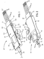
- a fanout connector generally designated 20 and which is fabricated of three major components.
- those components include a base housing, generally designated 22, and a cover, generally designated 24, which is slidably mounted onto the base housing in the direction of arrow "A".
- the base housing and cover form a housing means for receiving a third major component, namely a fanout insert, generally designated 26.
- a fiber optic cable 28 includes a plurality of individual optical fibers 30 which extend through the fanout insert and through a plurality of tubes 32 projecting forwardly of the insert.
- base housing 22 of fanout connector 20 includes a through passage, generally designated 34, for receiving cable 28 and fibers 30 along an axis 36.
- the base housing is a one-piece structure unitarily molded of plastic material and includes a bottom wall 38 and a pair of upstanding side walls 40 which define a receptacle 42 which communicates with or is a part of through passage 34.
- the receptacle generally is at a front end 44 of the housing, and a bottom lip 46 projects forwardly of front end 44.
- An entrance section 48 of through passage 34 opens at a rear end 50 of the housing and through which cable 28 extends. The entrance section is enlarged relative to the dimensions of the cable so that the cable is freely positioned within the enlarged entrance section as best seen in Figure 3.
- An intermediate section is defined by a pair of side walls 52 which gradually slope outwardly or diverge from entrance section 48 to receptacle 42.
- a plurality of guide rails 54 are located along the upper edges of side walls 40 of the base housing, with the guide rails opening inwardly toward axis 34.
- base housing 22 includes an upstanding octagonal mounting post 56, a rearwardly projecting strain relief tongue 58, a pair of upwardly opening latch recesses 60 (Fig. 4), a pair of bottom opening mounting holes 62 (Fig. 2) and a pair of cylindrical mounting members 64, all for purposes described hereinafter.
- Mounting members 64 are joined to one side wall 40 of the base housing by a pair of frangible webs 66.
- Cover 24 of connector 20 is a generally flat, elongated or rectangular member having guide ribs 68 along opposite edges thereof.
- the cover is a one-piece structure unitarily molded of plastic material.
- Guide ribs 68 slide beneath guide rails 54 of base housing 22 when the cover is slidably mounted to the housing in the direction of arrow "A" (Fig. 4) as described hereinafter.
- the cover has an upstanding octagonal mounting post 70 similar to upstanding mounting post 56 of the base housing.
- the cover has a forwardly projecting top lip 72 similar to bottom lip 46 of the base housing.
- the cover has a rearwardly projecting strain relief shroud 74 which cooperates with strain relief tongue 58 of the base housing to provide a strain relief means for cable 28, as will be seen hereinafter.
- the bottom of cover 24 has a pair of integrally molded latch bosses 76 which latch within recesses 60 (Fig. 4) of the base housing.
- a stop 78 also projects from the bottom of the cover.
- the cover includes a transparent window 80 which affords visual inspection of the cable within the connector.
- the entire cover may be molded of substantially transparent plastic material which is texturized in areas 82 so that substantially the entire cover is opaque except for transparent window 80.
- fanout insert 26 is molded of plastic material and includes a plurality of through holes 84 which receive fibers 30 of cable 28 and which spread the individual fibers apart from each other transversely of axis 36.
- the number of through holes does not have to match the number of fibers of the cable.
- the fibers extend through a plurality of tubes 32 projecting from a front end 86 of the fanout insert.
- the rear ends of the tubes preferably are fixed, as by epoxy, within the front ends of through holes 84.
- the fiber ends project beyond the front ends of the tubes as seen in the drawings.
- the tubes provide both protection for the projecting fibers as well as means for readily manipulating the fibers.
- the tubes themselves, are protected by forwardly projecting top lip 72 of the cover and bottom lip 46 of the base housing.
- Figure 6 shows how a plurality of connectors 20 can be mounted on top of each other in a stacked array.
- mounting post 56 which projects upwardly from base housing 22
- mounting post 70 which projects upwardly from cover 24 of a bottom connector are inserted into mounting holes 62 (Fig. 2) in the bottom of the base housing of a top connector. Therefore, the cover of the bottom connector cannot move relative to the base housing thereof.
- the mounting posts may be sized for positioning into the mounting holes by a press-fit.
- Figure 6 shows two connectors in a stacked array, of course more than two connectors can be stacked as described.
- the mounting posts 56 and 70 may be press fit into mounting holes in a printed circuit board (not shown).
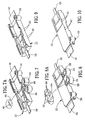
- FIGs 7-10 show how cylindrical mounting members 64 can be broken-away from base housing 22 for using the connector in applications wherein the connector is not mounted to a supporting structure.
- cylindrical mounting members 64 have through holes 88 (Figs. 7 and 8) for receiving therethrough appropriate fasteners, such as rivets, screws or bolts, for fastening the connector to an appropriate support structure.
- mounting members 64 are broken-away from base housing 22. This is accomplished by using frangible webs 66 which join the mounting members to the base housing and which are much smaller than the mounting members.
- Figures 7 and 7A show that notches 90 are formed at the tops of the webs immediately adjacent the housing.
- FIGs 8 and 8A show that notches 92 are formed at the bottoms of the webs immediately adjacent the housing. These notches weaken the junctures between the webs and the housing so that the webs readily break away from the housing leaving fairly clean breaking points as seen in Figures 9 and 10.
- fanout insert 26 includes a plurality of polarizing projections 94 on opposite sides thereof, and base housing 22 includes a plurality of polarizing projections 96 on the opposite sides of receptacle 42 defined by side walls 40.
- These complementary interengaging polarizing projections 94 and 96 define a tongue and groove arrangement at the sides of fanout insert 26 and the sides of receptacle 42 to ensure that the fanout insert is positioned in the receptacle only in a given orientation so that the fibers of cable 28 are oriented according to an expected scheme in which they have been threaded through the insert and through tubes 32.
- a small tube or band 98 is positioned about cable 28 at a point where the outer cladding of the cable has been removed to expose individual fibers 30.
- This band may be fabricated of heat shrinkable material and heat shrunk about the cable at this point. The band prevents the fibers from fraying the outer cladding of the cable after they have been exposed for spreading by fanout insert 26.
- the band is free to move within enlarged entrance section 48. This allows the cable and fibers to move axially of the entire connector within the limits of the band captured in the enlarged entrance section thereby improving temperature cycling performance. Stop 78 on the underside of cover 24 defines the forward limit of such movement.
- cover 24 is assembled to the base housing as shown in Figures 13 and 14. Specifically, the cover is slidably mounted to the base housing in the direction of arrows "A". During mounting, guide ribs 68 at opposite edges of the flat cover slide beneath guide rails 54 along the top edges of side walls 40 of the base housing. The cover is slidably mounted to the housing until a pair of stops 100 at opposite sides of the cover abut against a pair of stops 102 at opposite sides of the base housing as seen in Figure 1.
- cover 24 is fully slidably mounted onto base housing 22 with stops 100 and 102 in abutment, two functions occur as best seen in Figure 15.
- latch bosses 76 (Fig. 5) on the underside of cover 24 snap into latching interengagement with latch recesses 60 (Fig. 4) in the top of the base housing.
- strain relief tongue 58 at the rear of the base housing enters strain relief shroud 74 at the rear of the cover. This sandwiches cable 28 between the tongue and the cover.
- shroud 74 is flattened and is generally C-shaped to define a pair of bottom, inwardly directed flanges 74a.
- Tongue 58 also is flat, whereby ribbon cable 28 is sandwiched between the flat tongue and the flat top of the shroud, with flanges 74a of the shroud interengaging with the bottom of the tongue.
- the shroud is joined to t .è cover by a thin web 74b.
- web 74b of shroud 74 and tongue 58 are flexible whereby the interengaged strain relief means provide strain relief for the cable.
- latch bosses 76 and latch recesses 60 in relation to tongue 58 and shroud 74 preferably should be such that the tongue enters the shroud before the latch bosses of the cover engage the base housing which, otherwise, might move the tongue and shroud out of alignment. This can be seen in Figure 15 where tongue 58 has entered shroud. 54 before latch bosses 76 engage the housing for movement into the latch recesses.
- Figure 16 shows a connector 20A which does not include mounting post 56 (Fig. 4) on base housing 22 nor mounting post 70 (Fig. 4) on cover 24. This simply shows that the connector can be made for non-stackable applications.
Landscapes
- Physics & Mathematics (AREA)
- General Physics & Mathematics (AREA)
- Optics & Photonics (AREA)
- Mechanical Coupling Of Light Guides (AREA)
- Details Of Connecting Devices For Male And Female Coupling (AREA)
- Light Guides In General And Applications Therefor (AREA)
Applications Claiming Priority (2)
| Application Number | Priority Date | Filing Date | Title |
|---|---|---|---|
| US09/602,955 US6434315B1 (en) | 2000-06-23 | 2000-06-23 | Fiber optic connector |
| US602955 | 2000-06-23 |
Publications (3)
| Publication Number | Publication Date |
|---|---|
| EP1168016A2 EP1168016A2 (en) | 2002-01-02 |
| EP1168016A3 EP1168016A3 (en) | 2005-04-27 |
| EP1168016B1 true EP1168016B1 (en) | 2007-05-23 |
Family
ID=24413444
Family Applications (1)
| Application Number | Title | Priority Date | Filing Date |
|---|---|---|---|
| EP01114647A Expired - Lifetime EP1168016B1 (en) | 2000-06-23 | 2001-06-19 | Fiber optic connector |
Country Status (7)
| Country | Link |
|---|---|
| US (1) | US6434315B1 (ko) |
| EP (1) | EP1168016B1 (ko) |
| JP (1) | JP3629709B2 (ko) |
| KR (1) | KR100414844B1 (ko) |
| CN (1) | CN100343713C (ko) |
| DE (1) | DE60128515D1 (ko) |
| TW (1) | TW492544U (ko) |
Families Citing this family (16)
| Publication number | Priority date | Publication date | Assignee | Title |
|---|---|---|---|---|
| KR100440948B1 (ko) * | 2000-02-24 | 2004-07-21 | 삼성전자주식회사 | 휴대용 pc와 도킹 스테이션의 광 접속장치 |
| US7134200B2 (en) * | 2000-11-01 | 2006-11-14 | International Business Machines Corporation | Device and method for identifying cables |
| US7121732B2 (en) * | 2004-10-25 | 2006-10-17 | Panduit Corp. | Collet assembly with ribbon fiber holder |
| US7553091B2 (en) * | 2006-10-19 | 2009-06-30 | Avago Technologies Fiber Ip (Singapore) Pte. Ltd. | Stackable multi-optical fiber connector modules and devices for aligning sets of the stackable multi-optical fiber connector modules and coupling optical signals between them |
| CN100570420C (zh) * | 2006-10-19 | 2009-12-16 | 安华高科技光纤Ip(新加坡)私人有限公司 | 可堆叠多光纤连接器模块、使之对准并耦合光信号的装置 |
| US20080095502A1 (en) * | 2006-10-19 | 2008-04-24 | Mccolloch Laurence Ray | Stackable multi-optical fiber connector modules and devices for aligning sets of the stackable multi-optical fiber connector modules and coupling optical signals between them |
| US7543994B2 (en) * | 2006-10-19 | 2009-06-09 | Avago Technologies Fiber Ip (Singapore) Pte. Ltd. | Multi-optical fiber connector module for use with a transceiver module and method for coupling optical signals between the transceiver module and multiple optical fibers |
| US7738759B2 (en) * | 2007-03-16 | 2010-06-15 | 3M Innovative Properties Company | Optical fiber cable inlet device |
| US8622481B2 (en) | 2011-01-25 | 2014-01-07 | Joy Mm Delaware, Inc. | Fiber optic cable protection in a mining system |
| US8737796B2 (en) * | 2011-05-20 | 2014-05-27 | Adc Telecommunications, Inc. | Rapid universal rack mount enclosure |
| JP5716007B2 (ja) * | 2012-12-26 | 2015-05-13 | 株式会社フジクラ | 成端処理用キット及び光ファイバケーブルの成端方法 |
| US20150098684A1 (en) * | 2013-10-07 | 2015-04-09 | Tyco Electronics Corporation | Modular break out for cable assembly |
| WO2016115180A1 (en) * | 2015-01-12 | 2016-07-21 | Bustamante Nathan J | Fiber optic fan-out/break-out kit closure/housing |
| JP2017010666A (ja) * | 2015-06-18 | 2017-01-12 | 住友電気工業株式会社 | 配線部材 |
| US10247889B1 (en) * | 2018-05-15 | 2019-04-02 | Te Connectivity Corporation | Overmolded breakout |
| US11119284B2 (en) | 2018-08-31 | 2021-09-14 | Go!Foton Holdings, Inc. | Integrated connector cable |
Family Cites Families (13)
| Publication number | Priority date | Publication date | Assignee | Title |
|---|---|---|---|---|
| US3907397A (en) * | 1974-09-30 | 1975-09-23 | Augat Inc | High density connector plug assembly |
| US4606596A (en) * | 1984-11-19 | 1986-08-19 | E. I. Du Pont De Nemours And Company | Stress relief apparatus for electrical connectors |
| JPH0797164B2 (ja) * | 1988-08-23 | 1995-10-18 | 住友電気工業株式会社 | 光ファイバテープ心線の分岐部 |
| JP2566695B2 (ja) * | 1991-10-28 | 1996-12-25 | 日立電線株式会社 | 多心光コネクタ |
| US5315679A (en) * | 1992-04-27 | 1994-05-24 | International Business Machines Corporation | Optical fibers duplex connector assembly |
| US5224187A (en) * | 1992-04-29 | 1993-06-29 | Scientific-Atlanta, Inc. | Fiber optic cable connectors providing strain relief |
| US5420957A (en) * | 1994-06-22 | 1995-05-30 | At&T Corp. | Optical fiber cable splitter |
| US5604830A (en) | 1994-12-22 | 1997-02-18 | Hoechst Celanese Corp. | Multiple fiber connector for injection molded multiple fiberoptic coupler unit and cladding for same |
| US5778123A (en) * | 1996-03-12 | 1998-07-07 | Minnesota Mining And Manufacturing Company | Alignment assembly for multifiber or single fiber optical cable connector |
| JP3705883B2 (ja) * | 1996-12-04 | 2005-10-12 | 株式会社フジクラ | 光コネクタ |
| US5778122A (en) | 1996-12-24 | 1998-07-07 | Siecor Corporation | Fiber optic cable assembly for interconnecting optical fibers within a receptacle mounted within the wall of an enclosure |
| US5915055A (en) | 1997-06-30 | 1999-06-22 | Siecor Corporation | Method and apparatus for connectorizing fiber optic cable |
| JPH11185868A (ja) * | 1997-12-18 | 1999-07-09 | Yazaki Corp | 圧接コネクタ |
-
2000
- 2000-06-23 US US09/602,955 patent/US6434315B1/en not_active Expired - Fee Related
-
2001
- 2001-06-19 DE DE60128515T patent/DE60128515D1/de not_active Expired - Fee Related
- 2001-06-19 EP EP01114647A patent/EP1168016B1/en not_active Expired - Lifetime
- 2001-06-20 JP JP2001225177A patent/JP3629709B2/ja not_active Expired - Fee Related
- 2001-06-22 CN CNB011248408A patent/CN100343713C/zh not_active Expired - Fee Related
- 2001-06-23 KR KR10-2001-0036012A patent/KR100414844B1/ko not_active IP Right Cessation
- 2001-08-16 TW TW090210597U patent/TW492544U/zh not_active IP Right Cessation
Non-Patent Citations (1)
| Title |
|---|
| None * |
Also Published As
| Publication number | Publication date |
|---|---|
| TW492544U (en) | 2002-06-21 |
| US6434315B1 (en) | 2002-08-13 |
| KR20020000530A (ko) | 2002-01-05 |
| DE60128515D1 (de) | 2007-07-05 |
| CN1331422A (zh) | 2002-01-16 |
| JP2002139654A (ja) | 2002-05-17 |
| EP1168016A2 (en) | 2002-01-02 |
| KR100414844B1 (ko) | 2004-01-13 |
| JP3629709B2 (ja) | 2005-03-16 |
| EP1168016A3 (en) | 2005-04-27 |
| CN100343713C (zh) | 2007-10-17 |
Similar Documents
| Publication | Publication Date | Title |
|---|---|---|
| US6434316B1 (en) | Fiber optic connector | |
| US6623173B1 (en) | Fiber optic connector | |
| EP1168016B1 (en) | Fiber optic connector | |
| US11808994B1 (en) | Mini duplex connector with push-pull polarity mechanism and carrier | |
| US11493699B2 (en) | Multifiber fiber optic connectors, cable assemblies and methods of making the same | |
| US11573386B2 (en) | Fiber optic connector assembly, apparatus for forming a transceiver interface, and ferrule | |
| US6076975A (en) | Fiber optic connector assembly | |
| KR100204372B1 (ko) | 광섬유 커넥터용 어댑터 조립체 | |
| EP1221630B1 (en) | Connector assembly floating mount | |
| EP1485740B1 (en) | Device for aligning fiber optic connectors | |
| US5838856A (en) | Optical-fiber cable connector assembly | |
| EP1488267B1 (en) | Cable management system for fiber optic connector assemblies | |
| US20120141070A1 (en) | Connector assembly with improved structure on a bracket for mounting connectors | |
| EP1442327B1 (en) | Alignment pin assembly for fiber optic connectors | |
| US5127070A (en) | Optical fiber distribution module |
Legal Events
| Date | Code | Title | Description |
|---|---|---|---|
| PUAI | Public reference made under article 153(3) epc to a published international application that has entered the european phase |
Free format text: ORIGINAL CODE: 0009012 |
|
| AK | Designated contracting states |
Kind code of ref document: A2 Designated state(s): AT BE CH CY DE DK ES FI FR GB GR IE IT LI LU MC NL PT SE TR |
|
| AX | Request for extension of the european patent |
Free format text: AL;LT;LV;MK;RO;SI |
|
| RIN1 | Information on inventor provided before grant (corrected) |
Inventor name: MARRAPODE, THOMAS R. Inventor name: GROIS, IGOR Inventor name: MATASEK, JEFFREY A. Inventor name: KIM, BYUNG |
|
| PUAL | Search report despatched |
Free format text: ORIGINAL CODE: 0009013 |
|
| AK | Designated contracting states |
Kind code of ref document: A3 Designated state(s): AT BE CH CY DE DK ES FI FR GB GR IE IT LI LU MC NL PT SE TR |
|
| AX | Request for extension of the european patent |
Extension state: AL LT LV MK RO SI |
|
| 17P | Request for examination filed |
Effective date: 20051026 |
|
| AKX | Designation fees paid |
Designated state(s): DE FR GB IT |
|
| GRAP | Despatch of communication of intention to grant a patent |
Free format text: ORIGINAL CODE: EPIDOSNIGR1 |
|
| GRAS | Grant fee paid |
Free format text: ORIGINAL CODE: EPIDOSNIGR3 |
|
| GRAA | (expected) grant |
Free format text: ORIGINAL CODE: 0009210 |
|
| AK | Designated contracting states |
Kind code of ref document: B1 Designated state(s): DE FR GB IT |
|
| REG | Reference to a national code |
Ref country code: GB Ref legal event code: FG4D |
|
| REF | Corresponds to: |
Ref document number: 60128515 Country of ref document: DE Date of ref document: 20070705 Kind code of ref document: P |
|
| EN | Fr: translation not filed | ||
| PLBE | No opposition filed within time limit |
Free format text: ORIGINAL CODE: 0009261 |
|
| STAA | Information on the status of an ep patent application or granted ep patent |
Free format text: STATUS: NO OPPOSITION FILED WITHIN TIME LIMIT |
|
| GBPC | Gb: european patent ceased through non-payment of renewal fee |
Effective date: 20070823 |
|
| 26N | No opposition filed |
Effective date: 20080226 |
|
| PG25 | Lapsed in a contracting state [announced via postgrant information from national office to epo] |
Ref country code: IT Free format text: LAPSE BECAUSE OF FAILURE TO SUBMIT A TRANSLATION OF THE DESCRIPTION OR TO PAY THE FEE WITHIN THE PRESCRIBED TIME-LIMIT Effective date: 20070523 Ref country code: DE Free format text: LAPSE BECAUSE OF NON-PAYMENT OF DUE FEES Effective date: 20080101 |
|
| PG25 | Lapsed in a contracting state [announced via postgrant information from national office to epo] |
Ref country code: FR Free format text: LAPSE BECAUSE OF FAILURE TO SUBMIT A TRANSLATION OF THE DESCRIPTION OR TO PAY THE FEE WITHIN THE PRESCRIBED TIME-LIMIT Effective date: 20080118 |
|
| PG25 | Lapsed in a contracting state [announced via postgrant information from national office to epo] |
Ref country code: GB Free format text: LAPSE BECAUSE OF NON-PAYMENT OF DUE FEES Effective date: 20070823 |