EP1167995B1 - Matrix monopulse ratio radar processor for two target azimuth and elevation angle determination - Google Patents
Matrix monopulse ratio radar processor for two target azimuth and elevation angle determination Download PDFInfo
- Publication number
- EP1167995B1 EP1167995B1 EP01115823A EP01115823A EP1167995B1 EP 1167995 B1 EP1167995 B1 EP 1167995B1 EP 01115823 A EP01115823 A EP 01115823A EP 01115823 A EP01115823 A EP 01115823A EP 1167995 B1 EP1167995 B1 EP 1167995B1
- Authority
- EP
- European Patent Office
- Prior art keywords
- azimuth
- elevation
- matrix
- monopulse
- targets
- Prior art date
- Legal status (The legal status is an assumption and is not a legal conclusion. Google has not performed a legal analysis and makes no representation as to the accuracy of the status listed.)
- Expired - Lifetime
Links
Images


Classifications
-
- G—PHYSICS
- G01—MEASURING; TESTING
- G01S—RADIO DIRECTION-FINDING; RADIO NAVIGATION; DETERMINING DISTANCE OR VELOCITY BY USE OF RADIO WAVES; LOCATING OR PRESENCE-DETECTING BY USE OF THE REFLECTION OR RERADIATION OF RADIO WAVES; ANALOGOUS ARRANGEMENTS USING OTHER WAVES
- G01S13/00—Systems using the reflection or reradiation of radio waves, e.g. radar systems; Analogous systems using reflection or reradiation of waves whose nature or wavelength is irrelevant or unspecified
- G01S13/02—Systems using reflection of radio waves, e.g. primary radar systems; Analogous systems
- G01S13/06—Systems determining position data of a target
- G01S13/42—Simultaneous measurement of distance and other co-ordinates
- G01S13/44—Monopulse radar, i.e. simultaneous lobing
- G01S13/4418—Monopulse radar, i.e. simultaneous lobing with means for eliminating radar-dependent errors in angle measurements, e.g. multipath effects
Definitions
- This invention relates to arrangements, systems or receivers using monopulse techniques, such as those receivers used for radar surveillance or for radio frequency (RF) missile seekers, and more particularly to improved arrangements for locating targets, including up to two targets within the main beam of the antenna.
- monopulse techniques such as those receivers used for radar surveillance or for radio frequency (RF) missile seekers
- a monopulse antenna system includes plural antenna elements which receive the signal whose location is to be identified, and also includes various couplers which add the signals from various combinations of the antenna elements for generating sum signals, and azimuth and elevation difference signals.
- One type of prior-art monopulse antenna has four feed horns at the focus of a reflector, and a monopulse array antenna may have many antenna elements, beamformed to generate the desired sum and difference signals.
- the term “azimuth” and “elevation” are conventionally used, but refer to two mutually orthogonal measurements rather than to actual orientations.
- the presence of the target is determined by the existence of a signal within the sum beam.
- the elevation difference signal is divided by the sum signal to generate a value which establishes the elevation angle
- the azimuth difference signal is divided by the sum signal which determines the azimuth angle.
- the quotients of the divisions are applied to look-up tables in order to determine the corresponding angular location within an antenna beam.
- the beamwidth of an antenna is inversely related to the dimensions of an antenna measured in wavelengths; as the antenna gets smaller relative to the wavelength, the beamwidth gets larger.
- the time required to complete the volume scanning requires that the antenna beam be relatively broad or large.
- advanced search radar favors low frequency operation for low radar cross section (RCS) target detection advantage.
- RCS radar cross section
- the antenna beam of the scanning radar antenna being broad, is likely to contain a plurality of targets.
- the look-up tables of a monopulse antenna system cannot provide angles in the presence of multiple targets within the main beam of the antenna. Improved monopulse target or source location is desired.
- Modern high-resolution signal subspace algorithms such as MUSIC, root-MUSIC, minimum-norm algorithms and others overcome the beamwidth limitation by exploiting measurements over multiple channels with a multiple number of snapshots.
- these algorithms make use of the eigenstructure of the covariance matrix of sensor outputs to estimate the number of signal sources and the direction-of-arrival (DOA) of the sources.
- DOE direction-of-arrival
- These techniques exhibit a high-resolution capability in that they offer a practical means of separating them in less than the Rayleigh resolution limit determined by the antenna aperture size.
- conventional super-resolution algorithms such as MUSIC are computational intensive as it requires two-dimensional manifold search.
- these methods require multiple snapshots for covariance matrix estimation.
- a single snapshot technique based on four monopulse channels is also known and is based on measurement modeling and the algorithm involves a quadratic equation followed by a linear equation.
- the present invention is directed to a method and system for identifying the location or angular direction of a single target within the main beam of a monopulse antenna.
- the present invention also uses a matrix monopulse ratio processing technique to identify the location or angular direction of a single target within the main beam of a monopulse antenna as discussed in S.M. Sherman “Monopulse Principles and Techniques", Artech House, pages 339 - 343 or in US-A-5 371 506.
- the present invention is directed to a method and system for identifying the locations of plural targets lying within a main beam of a monopulse antenna including four ports for generating sum, elevation difference, azimuth difference and double difference signals.
- the method comprises the step of forming a monopulse ratio matrix from the sum, elevation difference, azimuth difference and double difference signals. Eigenvalues of the monopulse ratio matrix are determined, and values of the eigenvalues are used to determine the angular locations of the plural targets.
- the eigenvectors are determined by performing an eigenvalue decomposition of the complex monopulse ratio matrix to generate complex eigenvalues and the azimuth and elevation angle of the target can be determined from the real and imaginary part of the eigenvalue by the use of a look-up table.
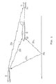
- an aircraft 10 is represented as being attacked by a missile 12.
- Missile 12 determines the location of the target aircraft 10 by use of radar using monopulse techniques.
- the target aircraft 10 defends itself by two different methods, namely by use of a decoy 14, and by use of a ground-pointing transponder 10t.
- Various radar signals are generated and irradiated and out via the missile 12, which are represented by "lighting bolt” symbols forming antenna beams 20a, 20b, and 20c 1 .
- Antenna beams 20a, 20b, and 20c 1 may be generated either simultaneously or sequentially.
- Antenna beam 20a is directed toward the decoy 14, beam 20b is directed toward the aircraft, and beam 20c 1 is directed toward the ground at a location 20g.
- the decoy 14 Since the decoy 14 is smaller than the aircraft, its radar signature or reflection as perceived by the missile on beam 20a would ordinarily be smaller than that of the aircraft as perceived on beam 20b.
- the decoy includes a transponder 14t, which receives the transmitted radar signals arriving over antenna beam 20a or 20b communicated through a cable between aircraft 10 and decoy 14, and amplifies and retransmits the signals. The amplified and retransmitted signals retrace their paths over beam 20a, and arrive back at the missile with greater amplitude than the signals transmitted over antenna beam 20b and reflected by aircraft 10.
- the aircraft 10 of Figure 1 may operate its ground-directed transponder 10t in such a manner as to retransmit those signals transmitted by missile 12 over antenna beam 20c 1 , reflected from that portion of the earth's surface lying near location 20g, and arriving at the aircraft 10 by way of path 20c 2 . At least some of the energy retransmitted by transponder 10t flows along path 20c 2 , is reflected from location 20g, and flows back along path 20c 1 to the missile.
- the transponder 10t may be used instead of the decoy 14, or in conjunction with the decoy 14, or the decoy 14 may be used alone. Regardless of which defense technique is used by aircraft 10, the missile receives strong signals from directions which are not the direction of the target aircraft, and may not be able to identify correctly the direction of the aircraft relative to the missile.
- the conventional monopulse system is incapable of separating the signals, and so a combined signal is used to access the look-up table which quantifies the shape of the main beam, with the result that the two targets may be misidentified as one, and the location of the "single" target will be in error.
- a method and system are provided in which a monopulse radar system is able to identify separately the aircraft 10 and the decoy 14, and to identify correctly the separate positions of there two objects.
- FIG 2a is a simplified physical representation of a four horn monopulse antenna 200.
- each of four horn apertures commonly referred to simply as horns, are designated as 201, 202, 203 and 204.
- Horn 201 lies over horn 203
- horn 202 lies over horn 204
- horns 201 and 202 lie above a horizontal plane of separation H.
- horns 201 and 203 lie to the left
- horns 202 and 204 lie to the right, of a vertically oriented plane of separation V.
- Figure 2b is a simplified illustration of the connections of horns 201, 202, 203 and 204 of antenna 200 of Figure 2a for generation of sum and difference beams.
- an output port 201P of horn 201 is connected to noninverting (+) input ports of summing circuits or adders 210, 214 and 218; and an output port 202P of horn 202 is connected to noninverting input ports of summing circuits 210, 216 and 220.
- An output port 203P of horn 203 is connected to noninverting input ports of summing circuits 212, 214 and 220; and an output port 204P of horn 204 is connected to noninverting input ports of summing circuits 212, 216 and 218.
- the signal at the output port 210o of summing circuit 210 represents the sum of the signals of horns 201 and 202, or in the notation of Figure 2b, "(1+2)".
- the output signal at output port 212o of summing circuit 212 represents the sum of the signals of horns 203 and 204, or (3+4)
- the output signal at output port 214o of summing circuit 214 represents (1+3).
- the output signal at output port 216o of summing circuit 216 represents (2+4)
- the output signal at output port 218o of summing circuit 218 represents (1+4)
- the output signal at output port 220o of summing circuit 220 represents (2+3).
- a summing circuit 222 has its noninverting input ports coupled to output ports 210o and 212o of summing circuits 210 and 212, respectively, for producing, at its output port 222o, the sum ( ⁇ ) signal representing (1+2) + (3+4).
- a summing circuit 224 has a noninverting input port coupled to output port 210o of summing circuit 210, and an inverting input port coupled to output port 212o of summing circuit 212, for producing, at its output port 224o, the elevation difference ( ⁇ EL ) signal representing (1+2)-(3+4).
- a summing circuit 226 has a noninverting input port coupled to output port 214o of summing circuit 214, and also has an inverting input port coupled to output port 216o of summing circuit 216, for producing, at its output port 226o, the azimuth difference ( ⁇ AZ ) signal representing (1+3)-(2+4).
- a summing circuit 228 has a noninverting input port coupled to output port 218o of summing circuit 218, and also has an inverting input port coupled to output port 220o of summing circuit 220, for producing, at its output port 228o, the double difference ( ⁇ ⁇ ) signal representing (1+4)-(2+3).
- Figures 2a and 2b represents only one kind of monopulse signal generating antenna.
- Other types are well known, including the array type, in which the beamformer generates the desired beams directly, and these other types of monopulse antennas may be used in a system according to the invention, so long as they are arranged to produce at least the sum signals, and azimuth, elevation, and double difference signals.
- the sum signal, and the azimuth and elevation signals are used to determine the location of a target.
- the monpulse ratio with respect to angle off boresight can be read off from a look-up table and is illustrated by Figure 3.
- the monopulse ratios can no longer give angle information of the targets.
- an additional channel is required.
- the present invention uses the double difference beam described earlier as this additional channel. This channel is typically not used in a conventional radar system. In an advanced radar system, the double-difference beam has been used as the auxiliary beam for mainlobe jamming cancellation application. In accordance with this invention this channel can also be used to generate the following monopulse ratios, for which the azimuth and elevation angle can be determined by the look-up table as before.
- m A ⁇ ⁇ ⁇ E
- m E ⁇ ⁇ ⁇ ⁇
- the monopulse ratios derived from the two ratios can be used as a consistency check for determination of one or more targets. For one target presence, the monopulse ratios using equations (1-4) serve as independent estimate and therefore can thus be averaged to get a better estimate. In the case of two targets within the main antenna beam, the azimuth and elevation monopulse values derived from (1) and (3) and (2) and (4) will not be equal.
- the monopulse values (m A1 ,m E1 ) and (m A2 , m E2 ) are the monopulse values of the two targets.
- the weights are the sum and difference pattern values correspondingly.
- the elevation monopulse ratio matrix has the following eigenvalue decomposition from which the elevation angles can be determined from a look-up table:
- the matrix monopulse ratio processing technique can be summarized as following:
- This algorithm requires two eigenvalue decomposition and azimuth and elevation angle paring. This procedure can further be refined by combining the above azimuth angle and elevation angle matrix processing using the following complex notations:
- the ⁇ , ⁇ ⁇ , ⁇ E and ⁇ ⁇ values are used to determine the monpulse ratios; and, at 404, these ratios are used to determine whether there is one target or two targets. If one target is present, then at 406, the azimuth and elevation angles of the target are obtained from a look-up table, using the monopulse ratios. If two targets are present, then at 410 the complex monopulse ratio matrix is established, and at 412, an eigenvalue decomposition of the matrix is performed. Then at 414 the azimuth and elevation angles for the targets are obtained from a look-up table using the extracted real and imaginary values of the eigenvalues.
- the antenna is circular with 9 inch diameter corresponding to beamwidth of 6 degrees.
- Two sources of azimuth and elevation angles of (0,0) and (3,3) are simulated with equal signal-to-noise ratios of 30 dB.
- Conventional monopulse processing estimates of 200 simulations are carried out and plotted in Figure 5.
- the angle estimates are seen to lie along the line 502 connecting the two sources, as suggested by the weighted expressions in equations (6-9). Applying the matrix monopulse ratios shows that there are two distinct sources, and each angle estimate scatters around its true angular location as illustrated at 602 and 604 in Figure 6.
Description


Claims (16)
- A method for processing information in a main beam of a monopulse antenna including four ports for generating sum, elevation difference, azimuth difference and double difference signals, the method comprising the steps of:forming (402) a set of monopulse ratios from the sum, elevation difference, azimuth difference and double difference signals; andcomparing (404) said ratios to determine whether there is one target or two targets lying within the main beam.
- The method according to claim 1, further comprising the step of, if there is one target lying within the main beam, averaging formed ratios to determine azimuth and elevation angles for said one target.
- The method according to claim 1 or 2, further comprising the step of, if there are two targets lying within the main beam, further processing the sum, elevation difference, azimuth difference, and double difference signal to determine azimuth and elevation angles for each of the targets.
- The method according to claim 3, further comprising the steps of:forming (410) a monopulse ratio matrix form the sum, elevation difference, azimuth difference and double difference signals;determining (412) eigenvalues of the monopulse ratio matrix; andusing the eigenvalues to determine the angular locations of the plural targets.
- A method according to claim 4, wherein the determining step includes the step of performing an eigenvalue decomposition of the monopulse ratio matrix to generate eigenvalues.
- The method according to claims 4 or 5, wherein:the forming step (410) includes the steps ofi) forming a monopulse ratio azimuth matrix, andii) forming a monopulse ratio elevation matrix;the determining step (412) includes the steps ofi) determining an eigenvalue decomposition of the monopulse ratio azimuth matrix, andii) determining an eigenvalue decomposition of the monopulse ratio elevation matrix; andthe using step (414) includes the steps ofi) using eigenvalues of the monopulse ratio azimuth matrix to determine azimuth angles of the targets, andii) using the eigenvalues of the monopulse ratio elevation matrix to determine elevation angles of the targets.
- The method according to claim 6, wherein the step of using the eigenvalues include the step of determining a pairing of azimuth and elevation angles of the targets based on the similarity of the eigenvectors of the monopulse ratio azimuth and elevation matrices.
- The method according to any one of claims 4 to 7, wherein the step of using the eigenvalues includes the step of using the eigenvalues to obtain angles of the targets from a look-up table.
- A system adapted to identify the locations of plural targets lying within a main beam of a monopulse antenna including four ports for generating sum, elevation difference, azimuth difference and double difference signals, the system comprising:means (402) adapted to form a set of monopulse ratios from the sum, elevation difference, azimuth difference and double difference signals; andmeans (404) adapted to compare said ratios to determine whether there is one target or two targets lying within the main beam.
- The system according to claim 9, further comprising means adapted to average formed ratios to determine azimuth and elevation angles for said one target, in the case that there is one target lying within the main beam.
- The system according to claims 9 or 10, further comprising means adapted to further process the sum, elevation difference, azimuth difference, and double difference signal to determine azimuth and elevation angles for each of the targets, in the case that there are two targets lying within the main beam.
- A system according to claim 11, further comprising
means (410) for forming a monopulse ratio matrix from the sum, elevation difference, azimuth difference and double difference signals;
means (412) for determining the eigenvalue decomposition of the monopulse ratio matrix; and
means (414) for using the eigenvectors to determine the angular locations of the plural targets. - The system according to claim 12, wherein the determining means includes the means for performing an eigenvalue decomposition of the monopulse ratio matrix to generate eigenvalues.
- The system according to claim 12, wherein:the forming means (410) includesi) means for forming a monopulse ratio azimuth matrix, andii) means for forming a monopulse ratio elevation matrix;the determining means (412) includesi) means for determining an eigenvalue decomposition of the monopulse ratio azimuth matrix, andii) means for determining an eigenvalue decomposition of the monopulse ratio elevation matrix; andthe using means (414) includesi) means for using the eigenvalues of the monopulse ratio azimuth matrix to determine azimuth angles of the targets, andii) means for using the eigenvalues of the monopulse ratio elevation matrix to determine elevation angles of the targets.
- The system according to claim 14, wherein the using means include the means for determining a pairing of azimuth and elevation angles of the targets based on the similarity of the eigenvectors of the monopulse ratio azimuth and elevation matrices.
- A system according to claim 12, wherein the using means includes means for using the eigenvalues to obtain angles of the targets from a look-up table.
Applications Claiming Priority (2)
| Application Number | Priority Date | Filing Date | Title |
|---|---|---|---|
| US09/607,004 US6404379B1 (en) | 2000-06-29 | 2000-06-29 | Matrix monopulse ratio radar processor for two target azimuth and elevation angle determination |
| US607004 | 2000-06-29 |
Publications (3)
| Publication Number | Publication Date |
|---|---|
| EP1167995A2 EP1167995A2 (en) | 2002-01-02 |
| EP1167995A3 EP1167995A3 (en) | 2002-09-11 |
| EP1167995B1 true EP1167995B1 (en) | 2005-04-13 |
Family
ID=24430389
Family Applications (1)
| Application Number | Title | Priority Date | Filing Date |
|---|---|---|---|
| EP01115823A Expired - Lifetime EP1167995B1 (en) | 2000-06-29 | 2001-06-28 | Matrix monopulse ratio radar processor for two target azimuth and elevation angle determination |
Country Status (3)
| Country | Link |
|---|---|
| US (1) | US6404379B1 (en) |
| EP (1) | EP1167995B1 (en) |
| DE (1) | DE60109990T2 (en) |
Families Citing this family (22)
| Publication number | Priority date | Publication date | Assignee | Title |
|---|---|---|---|---|
| US6622118B1 (en) | 2001-03-13 | 2003-09-16 | Alphatech, Inc. | System and method for comparing signals |
| US6720910B2 (en) * | 2001-08-16 | 2004-04-13 | Lockheed Martin Corporation | Pri-staggered post-doppler adaptive monopulse processing for detection and location of a moving target in ground clutter |
| US6498581B1 (en) * | 2001-09-05 | 2002-12-24 | Lockheed Martin Corporation | Radar system and method including superresolution raid counting |
| US6567034B1 (en) * | 2001-09-05 | 2003-05-20 | Lockheed Martin Corporation | Digital beamforming radar system and method with super-resolution multiple jammer location |
| US7136012B2 (en) * | 2003-04-01 | 2006-11-14 | Lockheed Martin Corporation | Approach radar with array antenna having rows and columns skewed relative to the horizontal |
| US6801156B1 (en) * | 2003-07-25 | 2004-10-05 | Lockheed Martin Corporation | Frequency-agile monopulse technique for resolving closely spaced targets |
| US7205932B2 (en) * | 2004-01-29 | 2007-04-17 | Bae Systems Information And Electronic Systems Integration Inc. | Method and apparatus for improved determination of range and angle of arrival utilizing a two tone CW radar |
| US7250902B2 (en) * | 2005-07-19 | 2007-07-31 | Raytheon Company | Method of generating accurate estimates of azimuth and elevation angles of a target for a phased—phased array rotating radar |
| JP4351266B2 (en) * | 2007-05-10 | 2009-10-28 | 三菱電機株式会社 | Frequency modulation radar equipment |
| US7535408B2 (en) * | 2007-08-31 | 2009-05-19 | Lockheed Martin Corporation | Apparatus and methods for detection of multiple targets within radar resolution cell |
| US7671789B1 (en) | 2008-10-03 | 2010-03-02 | Lockheed Martin Corporation | Method and system for target detection and angle estimation based on a radar signal |
| US7859451B2 (en) * | 2008-11-18 | 2010-12-28 | Lockheed Martin Corporation | Method and system for monopulse radar target angle determination |
| US8269665B1 (en) * | 2010-01-29 | 2012-09-18 | Lockheed Martin Corporation | Monopulse angle determination |
| CH704552A8 (en) * | 2011-02-17 | 2012-10-15 | Huber+Suhner Ag | Array antenna. |
| US8577298B2 (en) * | 2011-06-20 | 2013-11-05 | Lockheed Martin Corporation | Multi-element magnetic receiver for interference suppression and signal enhancement |
| RU2622399C1 (en) * | 2016-07-06 | 2017-06-15 | Федеральное государственное автономное образовательное учреждение высшего образования "Санкт-Петербургский государственный университет аэрокосмического приборостроения" (ГУАП) | Quasi-mono-pulse secondary radar |
| US10705202B2 (en) * | 2017-01-19 | 2020-07-07 | GM Global Technology Operations LLC | Iterative approach to achieve angular ambiguity resolution |
| WO2019171828A1 (en) * | 2018-03-06 | 2019-09-12 | 日立オートモティブシステムズ株式会社 | Radar device |
| KR102122829B1 (en) | 2018-04-10 | 2020-06-15 | 고려대학교 산학협력단 | Target Location Estimation Method for Distributed MIMO Radar using Extended BRM Scheme |
| CN110068833B (en) * | 2019-05-05 | 2021-10-29 | 中国科学院电子学研究所 | Synthetic aperture laser radar imaging method, instrument and system |
| CN113609450B (en) * | 2021-02-22 | 2023-11-03 | 天津大学 | Large-scale sparse array DoA estimation method based on LCGAMP network and 1-Bit quantization |
| CN113777415A (en) * | 2021-08-24 | 2021-12-10 | 中电科思仪科技股份有限公司 | Method for quickly aligning electric axis in antenna housing test based on phase sum-difference method |
Family Cites Families (12)
| Publication number | Priority date | Publication date | Assignee | Title |
|---|---|---|---|---|
| US3471857A (en) * | 1967-05-24 | 1969-10-07 | Singer General Precision | Planar array antenna arrangements |
| US4005421A (en) * | 1973-05-30 | 1977-01-25 | Westinghouse Electric Corporation | Monopulse radar system and method for improved low elevation tracking |
| US3935572A (en) * | 1973-11-23 | 1976-01-27 | Hughes Aircraft Company | System for resolving velocity ambiguity in pulse-doppler radar |
| FR2527785A1 (en) * | 1982-05-27 | 1983-12-02 | Thomson Csf | METHOD AND DEVICE FOR REDUCING THE POWER OF THE INTERFERENCE SIGNALS RECEIVED BY THE LATERAL LOBES OF A RADAR ANTENNA |
| US6195035B1 (en) * | 1984-10-12 | 2001-02-27 | Textron Systems Corporation | Cylindrical monopulse |
| DE3630482A1 (en) * | 1986-09-08 | 1988-05-11 | Uhland Goebel | Circulator having a reversible transmission direction |
| US5059968A (en) * | 1990-12-11 | 1991-10-22 | Raytheon Company | Radar system and method of operating such system |
| US5302961A (en) * | 1992-12-28 | 1994-04-12 | General Electric Co. | Antenna aperture with mainlobe jammer nulling capability |
| US5371506A (en) * | 1993-07-19 | 1994-12-06 | General Electric Co. | Simultaneous multibeam approach for cancelling multiple mainlobe jammers while preserving monopulse angle estimation accuracy on mainlobe targets |
| WO1997022890A1 (en) * | 1995-12-19 | 1997-06-26 | Siemens Schweiz Ag | Process and amplitude or phase-single pulse radar device for locating flying objects |
| US6087974A (en) * | 1998-08-03 | 2000-07-11 | Lockheed Martin Corporation | Monopulse system for target location |
| IL126284A (en) * | 1998-09-17 | 2002-12-01 | Netmor Ltd | System and method for three dimensional positioning and tracking |
-
2000
- 2000-06-29 US US09/607,004 patent/US6404379B1/en not_active Expired - Fee Related
-
2001
- 2001-06-28 DE DE60109990T patent/DE60109990T2/en not_active Expired - Lifetime
- 2001-06-28 EP EP01115823A patent/EP1167995B1/en not_active Expired - Lifetime
Also Published As
| Publication number | Publication date |
|---|---|
| EP1167995A3 (en) | 2002-09-11 |
| EP1167995A2 (en) | 2002-01-02 |
| DE60109990D1 (en) | 2005-05-19 |
| US6404379B1 (en) | 2002-06-11 |
| DE60109990T2 (en) | 2006-05-04 |
Similar Documents
| Publication | Publication Date | Title |
|---|---|---|
| EP1167995B1 (en) | Matrix monopulse ratio radar processor for two target azimuth and elevation angle determination | |
| EP1348978B1 (en) | Radar processing system and method for detecting and maintaining targets | |
| US6087974A (en) | Monopulse system for target location | |
| US5600326A (en) | Adaptive digital beamforming architecture and algorithm for nulling mainlobe and multiple sidelobe radar jammers while preserving monopulse ratio angle estimation accuracy | |
| US6661366B2 (en) | Adaptive digital sub-array beamforming and deterministic sum and difference beamforming, with jamming cancellation and monopulse ratio preservation | |
| US5371506A (en) | Simultaneous multibeam approach for cancelling multiple mainlobe jammers while preserving monopulse angle estimation accuracy on mainlobe targets | |
| US6580392B2 (en) | Digital beamforming for passive detection of target using reflected jamming echoes | |
| US6720910B2 (en) | Pri-staggered post-doppler adaptive monopulse processing for detection and location of a moving target in ground clutter | |
| US5907302A (en) | Adaptive elevational scan processor statement of government interest | |
| Li et al. | Combining sum-difference and auxiliary beams for adaptive monopulse in jamming | |
| Nickel | Array processing for radar: achievements and challenges | |
| WO2010039299A1 (en) | Counter target acquisition radar and acoustic adjunct for classification | |
| Kuschel | VHF/UHF radar. Part 2: Operational aspects and applications | |
| Villano et al. | Antenna array for passive radar: configuration design and adaptive approaches to disturbance cancellation | |
| Hiemstra | Robust implementations of the multistage Wiener filter | |
| US3787849A (en) | Airborne digital moving target detector | |
| EP1167994B1 (en) | Monopulse radar processor for resolving two sources | |
| US20030184473A1 (en) | Adaptive digital sub-array beamforming and deterministic sum and difference beamforming, with jamming cancellation and monopulse ratio preservation | |
| Narasimhan et al. | Mitigation of sidelobe clutter discrete using sidelobe blanking technique in airborne radars | |
| Wang et al. | Target polarization scattering matrix estimation with conformal MIMO radar | |
| Bialer et al. | A Multi-radar Joint Beamforming Method | |
| Zemmari et al. | On angle estimation in GSM passive coherent location systems | |
| Riddolls | Practical beamspace MIMO approach for auroral clutter control in over-the-horizon radar | |
| Bathurst et al. | Design considerations for a shipboard MIMO radar for surface target detection | |
| Alibrahim | Direction of arrival estimation for spinning antenna based electronic intelligence systems |
Legal Events
| Date | Code | Title | Description |
|---|---|---|---|
| PUAI | Public reference made under article 153(3) epc to a published international application that has entered the european phase |
Free format text: ORIGINAL CODE: 0009012 |
|
| AK | Designated contracting states |
Kind code of ref document: A2 Designated state(s): AT BE CH CY DE DK ES FI FR GB GR IE IT LI LU MC NL PT SE TR |
|
| AX | Request for extension of the european patent |
Free format text: AL;LT;LV;MK;RO;SI |
|
| RIN1 | Information on inventor provided before grant (corrected) |
Inventor name: ZHENG, YIBIN Inventor name: YU, KAI-BOR |
|
| PUAL | Search report despatched |
Free format text: ORIGINAL CODE: 0009013 |
|
| AK | Designated contracting states |
Kind code of ref document: A3 Designated state(s): AT BE CH CY DE DK ES FI FR GB GR IE IT LI LU MC NL PT SE TR |
|
| AX | Request for extension of the european patent |
Free format text: AL;LT;LV;MK;RO;SI |
|
| 17P | Request for examination filed |
Effective date: 20021128 |
|
| AKX | Designation fees paid |
Designated state(s): DE FR GB IT |
|
| 17Q | First examination report despatched |
Effective date: 20030922 |
|
| GRAP | Despatch of communication of intention to grant a patent |
Free format text: ORIGINAL CODE: EPIDOSNIGR1 |
|
| GRAS | Grant fee paid |
Free format text: ORIGINAL CODE: EPIDOSNIGR3 |
|
| GRAA | (expected) grant |
Free format text: ORIGINAL CODE: 0009210 |
|
| AK | Designated contracting states |
Kind code of ref document: B1 Designated state(s): DE FR GB IT |
|
| REG | Reference to a national code |
Ref country code: GB Ref legal event code: FG4D |
|
| REG | Reference to a national code |
Ref country code: IE Ref legal event code: FG4D |
|
| REF | Corresponds to: |
Ref document number: 60109990 Country of ref document: DE Date of ref document: 20050519 Kind code of ref document: P |
|
| PLBE | No opposition filed within time limit |
Free format text: ORIGINAL CODE: 0009261 |
|
| STAA | Information on the status of an ep patent application or granted ep patent |
Free format text: STATUS: NO OPPOSITION FILED WITHIN TIME LIMIT |
|
| ET | Fr: translation filed | ||
| 26N | No opposition filed |
Effective date: 20060116 |
|
| PGFP | Annual fee paid to national office [announced via postgrant information from national office to epo] |
Ref country code: FR Payment date: 20060620 Year of fee payment: 6 |
|
| REG | Reference to a national code |
Ref country code: FR Ref legal event code: ST Effective date: 20080229 |
|
| PG25 | Lapsed in a contracting state [announced via postgrant information from national office to epo] |
Ref country code: FR Free format text: LAPSE BECAUSE OF NON-PAYMENT OF DUE FEES Effective date: 20070702 |
|
| PGFP | Annual fee paid to national office [announced via postgrant information from national office to epo] |
Ref country code: IT Payment date: 20100624 Year of fee payment: 10 |
|
| PGFP | Annual fee paid to national office [announced via postgrant information from national office to epo] |
Ref country code: GB Payment date: 20100625 Year of fee payment: 10 Ref country code: DE Payment date: 20100629 Year of fee payment: 10 |
|
| GBPC | Gb: european patent ceased through non-payment of renewal fee |
Effective date: 20110628 |
|
| PG25 | Lapsed in a contracting state [announced via postgrant information from national office to epo] |
Ref country code: IT Free format text: LAPSE BECAUSE OF NON-PAYMENT OF DUE FEES Effective date: 20110628 |
|
| REG | Reference to a national code |
Ref country code: DE Ref legal event code: R119 Ref document number: 60109990 Country of ref document: DE Effective date: 20120103 |
|
| PG25 | Lapsed in a contracting state [announced via postgrant information from national office to epo] |
Ref country code: DE Free format text: LAPSE BECAUSE OF NON-PAYMENT OF DUE FEES Effective date: 20120103 |
|
| PG25 | Lapsed in a contracting state [announced via postgrant information from national office to epo] |
Ref country code: GB Free format text: LAPSE BECAUSE OF NON-PAYMENT OF DUE FEES Effective date: 20110628 |