US10705202B2 - Iterative approach to achieve angular ambiguity resolution - Google Patents
Iterative approach to achieve angular ambiguity resolution Download PDFInfo
- Publication number
- US10705202B2 US10705202B2 US15/409,986 US201715409986A US10705202B2 US 10705202 B2 US10705202 B2 US 10705202B2 US 201715409986 A US201715409986 A US 201715409986A US 10705202 B2 US10705202 B2 US 10705202B2
- Authority
- US
- United States
- Prior art keywords
- target
- angle
- azimuth angle
- elevation angle
- elevation
- Prior art date
- Legal status (The legal status is an assumption and is not a legal conclusion. Google has not performed a legal analysis and makes no representation as to the accuracy of the status listed.)
- Active, expires
Links
- 238000013459 approach Methods 0.000 title description 2
- 239000011159 matrix material Substances 0.000 claims abstract description 30
- 238000005259 measurement Methods 0.000 claims abstract description 25
- 238000000034 method Methods 0.000 claims abstract description 19
- 230000033001 locomotion Effects 0.000 claims abstract description 13
- 238000012545 processing Methods 0.000 claims abstract description 7
- 238000012804 iterative process Methods 0.000 claims abstract description 6
- 230000008569 process Effects 0.000 description 6
- 230000006870 function Effects 0.000 description 4
- 230000005540 biological transmission Effects 0.000 description 3
- 230000008859 change Effects 0.000 description 2
- 230000007423 decrease Effects 0.000 description 2
- 238000010586 diagram Methods 0.000 description 2
- 230000003068 static effect Effects 0.000 description 2
- 238000010276 construction Methods 0.000 description 1
- 238000003384 imaging method Methods 0.000 description 1
- 230000006872 improvement Effects 0.000 description 1
- 239000000463 material Substances 0.000 description 1
- 238000012986 modification Methods 0.000 description 1
- 230000004048 modification Effects 0.000 description 1
- 230000004044 response Effects 0.000 description 1
Images


Classifications
-
- G—PHYSICS
- G01—MEASURING; TESTING
- G01S—RADIO DIRECTION-FINDING; RADIO NAVIGATION; DETERMINING DISTANCE OR VELOCITY BY USE OF RADIO WAVES; LOCATING OR PRESENCE-DETECTING BY USE OF THE REFLECTION OR RERADIATION OF RADIO WAVES; ANALOGOUS ARRANGEMENTS USING OTHER WAVES
- G01S13/00—Systems using the reflection or reradiation of radio waves, e.g. radar systems; Analogous systems using reflection or reradiation of waves whose nature or wavelength is irrelevant or unspecified
- G01S13/88—Radar or analogous systems specially adapted for specific applications
- G01S13/89—Radar or analogous systems specially adapted for specific applications for mapping or imaging
- G01S13/90—Radar or analogous systems specially adapted for specific applications for mapping or imaging using synthetic aperture techniques, e.g. synthetic aperture radar [SAR] techniques
-
- G—PHYSICS
- G01—MEASURING; TESTING
- G01S—RADIO DIRECTION-FINDING; RADIO NAVIGATION; DETERMINING DISTANCE OR VELOCITY BY USE OF RADIO WAVES; LOCATING OR PRESENCE-DETECTING BY USE OF THE REFLECTION OR RERADIATION OF RADIO WAVES; ANALOGOUS ARRANGEMENTS USING OTHER WAVES
- G01S13/00—Systems using the reflection or reradiation of radio waves, e.g. radar systems; Analogous systems using reflection or reradiation of waves whose nature or wavelength is irrelevant or unspecified
- G01S13/88—Radar or analogous systems specially adapted for specific applications
- G01S13/93—Radar or analogous systems specially adapted for specific applications for anti-collision purposes
- G01S13/931—Radar or analogous systems specially adapted for specific applications for anti-collision purposes of land vehicles
-
- G—PHYSICS
- G01—MEASURING; TESTING
- G01S—RADIO DIRECTION-FINDING; RADIO NAVIGATION; DETERMINING DISTANCE OR VELOCITY BY USE OF RADIO WAVES; LOCATING OR PRESENCE-DETECTING BY USE OF THE REFLECTION OR RERADIATION OF RADIO WAVES; ANALOGOUS ARRANGEMENTS USING OTHER WAVES
- G01S13/00—Systems using the reflection or reradiation of radio waves, e.g. radar systems; Analogous systems using reflection or reradiation of waves whose nature or wavelength is irrelevant or unspecified
- G01S13/88—Radar or analogous systems specially adapted for specific applications
- G01S13/89—Radar or analogous systems specially adapted for specific applications for mapping or imaging
- G01S13/90—Radar or analogous systems specially adapted for specific applications for mapping or imaging using synthetic aperture techniques, e.g. synthetic aperture radar [SAR] techniques
- G01S13/904—SAR modes
Definitions
- the subject invention relates to an iterative approach to achieve angular ambiguity resolution.
- a synthetic aperture radar is a radar that uses the motion of the antenna to improve spatial resolution.
- the distance that the SAR travels in the time it takes for reflections to return to the antenna based on transmitted pulses creates a synthetic antenna aperture that is larger than the actual antenna size.
- Increased antenna aperture improves image resolution of the two- or three-dimensional image obtained with the SAR.
- a beamforming antenna transmits the pulses at a selected angle.
- a method of achieving angular ambiguity resolution in a two-dimensional Doppler synthetic aperture radar system includes transmitting pulses using a plurality of transmit elements during movement of a platform on which the system is mounted, receiving reflections from a target resulting from the pulses, and processing the reflections to determine a Doppler measurement, the processing including subtracting a component specific to the movement of the platform to isolate movement of the target in the Doppler measurement. Determining a target azimuth angle and a target elevation angle to the target is based on an iterative process that includes estimating the target elevation angle or the target azimuth angle and then determining the target azimuth angle or the target elevation angle, respectively, based on a beamforming matrix.
- the beamforming matrix indicates amplitude and phase at each azimuth angle and each elevation angle among a set of azimuth angles and a set of elevation angles.
- a system to achieve angular ambiguity resolution using includes a platform to move, a two-dimensional Doppler synthetic aperture radar mounted on the platform to transmit pulses and receive reflections resulting from the pulses, and a memory to store a beamforming matrix.
- the beamforming matrix indicates amplitude and phase at each azimuth angle and each elevation angle among a set of azimuth angles and a set of elevation angles.
- the system also includes a processor to obtain a Doppler measurement specific to a target and determine a target azimuth angle and a target elevation angle to the target based on an iterative process that includes estimating the target elevation angle or the target azimuth angle and then determining the target azimuth angle or the target elevation angle, respectively, based on the beamforming matrix.
- FIG. 1 shows the angle resolution resulting for a platform of a radar system according to one or more embodiments at different speeds
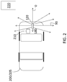
- FIG. 2 is a schematic diagram of a radar system according to one or more embodiments.
- FIG. 3 is a process flow of a method of resolving angular ambiguity in azimuth and elevation according to one or more embodiments.
- angular ambiguity in azimuth and elevation is an issue associated with Dopper SAR systems. While SAR was traditionally used in aircraft and spaceborne vehicles, it is increasing used in terrestrial vehicles such as automobiles, for example. As previously indicated, the moving platform on which the radar system is mounted forms a larger synthetic aperture with enhanced angle resolution as compared with the dimensions of the real antenna array. The narrow beam capability of a SAR radar system facilitates multi-target discrimination and imaging. While the synthetic array length increases linearly with the speed of the platform on which the radar system is mounted, the beam resolution or angular resolution decreases exponentially with platform speed.
- One or more embodiments of the systems and methods detailed herein relate to iteratively resolving ambiguity in angular resolution of the two-dimensional Doppler SAR based on a beamforming matrix.
- the beamforming matrix is a data structure such as a table, for example, that indicates the response in phase and amplitude of the reflection coming from each direction of arrival at each array element. Beamforming alone represents an inefficient solution to angular resolution because its performance is determined solely by array aperture. However, according to one or more embodiments, an elevation estimate is refined using the beamforming matrix to determine both elevation and azimuth of the target.
- FIG. 1 shows the angle resolution resulting for a platform of a radar system according to one or more embodiments at different speeds.
- the axis 110 indicates look angle in degrees from the platform, and the axis 120 indicates angle resolution in degrees associated with each look angle.
- Five different curves are shown for five different speeds of the platform on which the radar system is mounted. The speed is in kilometers/hour.
- the angular resolution is lowest, for any speed, at a look angle of 90 degrees. Angular resolution decreases progressively with increasing platform speed. As such, the lowest angular resolution shown in FIG. 1 for any look angle is associated with the highest platform speed shown, 100 kilometers/hour.
- the Doppler measurement is a function of: vcos ⁇ [FN. 1] In FN. 1, v is the velocity of the platform on which the radar system is mounted, and ⁇ is the look angle. As FN. 1 indicates, the look angle ⁇ can be determined from the Doppler measurement in this case of a one-dimensional angle.
- the radar system measures the projection of the static target velocity relative to the platform.
- the resulting one dimensional projection vector of target velocity must be resolved in azimuth and elevation. That is, the Doppler measurement is a function of: v cos ( ⁇ ) cos ( ⁇ ) [FN. 2]
- ⁇ is the look angle in azimuth
- co is the look angle in elevation. While determining the one-dimensional look angle based on the Doppler measurement according to FN. 1 is straight-forward, resolving the ambiguity between the azimuth and elevation contributions of the look angle, according to FN. 2, is more challenging. Embodiments of the systems and methods detailed herein relate to iteratively resolving the angular ambiguity in a moving-platform based radar system that is a two-dimensional Doppler SAR.
- FIG. 2 is a schematic diagram of a radar system 120 according to one or more embodiments.
- the radar system 120 is a Doppler SAR that obtains velocity, range, and two-dimensional look angle (azimuth and elevation) to a target 220 .
- the radar system 120 is mounted on a platform 200 that is an automobile 205 in the example shown in FIG. 2 .
- the platform 200 can be another type of vehicle (e.g., construction vehicle, farm vehicle) or equipment in an automated factory, for example.
- the platform 200 can be any moving support for the radar system 120 .
- a controller 210 can be coupled to the radar system.
- the controller 210 includes processing circuitry that may include an application specific integrated circuit (ASIC), an electronic circuit, a processor (shared, dedicated, or group) and memory that executes one or more software or firmware programs, a combinational logic circuit, and/or other suitable components that provide the described functionality.
- ASIC application specific integrated circuit
- the controller 210 can be involved in other systems of the automobile 205 such as the collision avoidance, automatic braking, and automated driving systems.
- the radar system 120 includes known components such as a transmit portion, a receive portion and antennas that are either dedicated to transmission or reception or function in a transceiver configuration.
- the radar system 120 can be a multi-input multi-output (MIMO) radar with multiple transmit elements and multiple receive elements or, in an alternate embodiment, can have multiple transmit elements and a single receive element. Each receive element receives reflections resulting from transmission by every transmit element.
- the size of the beamforming matrix is a function of the field of view and resolution in azimuth and elevation.
- the beamforming matrix can be stored by the controller 210 , for example.
- FIG. 3 is a process flow of a method of resolving angular ambiguity of a target 220 in azimuth and elevation according to one or more embodiments.
- obtaining a Doppler measurement includes obtaining a measurement that corresponds with FN. 2.
- Obtaining the Doppler measurement also includes isolating the Doppler measurement resulting from movement of the target 220 by subtracting the contribution from movement of the platform 200 .
- the odometer, controller 210 , or a combination of components can provide information about the platform 200 movement, and the controller 210 or other processor can obtain the Doppler measurement that is specific to the movement of the target 220 .
- the azimuth angle ( ⁇ ) is determined.
- the beamforming matrix which can be stored in a database 340 , for example, is searched.
- the database 340 can be part of the controller 210 .
- the azimuth angle corresponding with the maximum amplitude in the beamforming matrix for the elevation angle (estimated at block 320 ) is found.
- FN. 2 can be used to refine the elevation estimate (at block 320 ).
- FIG. 3 indicates, these processes of estimating elevation angle (at block 320 ) and finding azimuth angle according to the beamforming matrix (at block 330 ) are repeated iteratively.
- the iterative process can stop based on different conditions that are checked at block 350 .
- the check at block 350 can be a threshold change in angles between two consecutive iterations can be used as a condition to stop the iterations (e.g., angles did not change by more than 0.5 degrees from the last iteration).
- the iterations can continue until there is no improvement in the amplitude value associated with the latest elevation angle and azimuth angle.
- the azimuth angle can instead be estimated (at block 320 ), and the elevation angle can be determined (at block 330 ) based on the beamforming matrix.
- the angle determination that is based on the beamforming matrix (at block 330 ) can be more accurate than the estimate based on FN. 2 (at block 320 ).
- the specific embodiment that is used to determine elevation angle and azimuth angle can be selected based on which angle is deemed to be more critical.
- the processes discussed with reference to FIG. 3 can be extended for multiple targets 220 . That is, the processes can be repeated for each target 220 .
- the elevation angle and azimuth angle can be estimated, using the processes discussed with reference to FIG. 3 , for the target 220 that results in the strongest reflections (highest amplitude values) first, and angles to additional targets 220 can be determined in order of highest to lowest amplitude of the reflections.
Abstract
Description
vcosθ [FN. 1]
In FN. 1, v is the velocity of the platform on which the radar system is mounted, and θ is the look angle. As FN. 1 indicates, the look angle θ can be determined from the Doppler measurement in this case of a one-dimensional angle.
v cos (θ) cos (φ) [FN. 2]
Claims (12)
v cos (θ) cos (φ),
v cos (θ) cos (φ),
Priority Applications (3)
| Application Number | Priority Date | Filing Date | Title |
|---|---|---|---|
| US15/409,986 US10705202B2 (en) | 2017-01-19 | 2017-01-19 | Iterative approach to achieve angular ambiguity resolution |
| CN201810032289.3A CN108333588B (en) | 2017-01-19 | 2018-01-12 | Iterative method for obtaining an angular ambiguity resolution |
| DE102018101120.2A DE102018101120B4 (en) | 2017-01-19 | 2018-01-18 | Iterative approach to achieve angle ambiguity resolution |
Applications Claiming Priority (1)
| Application Number | Priority Date | Filing Date | Title |
|---|---|---|---|
| US15/409,986 US10705202B2 (en) | 2017-01-19 | 2017-01-19 | Iterative approach to achieve angular ambiguity resolution |
Publications (2)
| Publication Number | Publication Date |
|---|---|
| US20180203108A1 US20180203108A1 (en) | 2018-07-19 |
| US10705202B2 true US10705202B2 (en) | 2020-07-07 |
Family
ID=62716669
Family Applications (1)
| Application Number | Title | Priority Date | Filing Date |
|---|---|---|---|
| US15/409,986 Active 2038-09-29 US10705202B2 (en) | 2017-01-19 | 2017-01-19 | Iterative approach to achieve angular ambiguity resolution |
Country Status (3)
| Country | Link |
|---|---|
| US (1) | US10705202B2 (en) |
| CN (1) | CN108333588B (en) |
| DE (1) | DE102018101120B4 (en) |
Cited By (1)
| Publication number | Priority date | Publication date | Assignee | Title |
|---|---|---|---|---|
| US20200217950A1 (en) * | 2019-01-07 | 2020-07-09 | Qualcomm Incorporated | Resolution of elevation ambiguity in one-dimensional radar processing |
Families Citing this family (8)
| Publication number | Priority date | Publication date | Assignee | Title |
|---|---|---|---|---|
| US10690743B2 (en) | 2017-08-17 | 2020-06-23 | GM Global Technology Operations LLC | Doppler measurements to resolve angle of arrival ambiguity of wide aperture radar |
| DE102018200814B3 (en) * | 2018-01-18 | 2019-07-18 | Audi Ag | Method for operating a fully automatic guidance of a motor vehicle trained vehicle guidance system of the motor vehicle and motor vehicle |
| US10365364B1 (en) * | 2018-05-18 | 2019-07-30 | Zendar Inc. | Systems and methods for detecting objects |
| US10371797B1 (en) | 2018-05-23 | 2019-08-06 | Zendar Inc. | Systems and methods for enhancing target detection |
| KR102516367B1 (en) * | 2018-09-03 | 2023-03-31 | 삼성전자주식회사 | Method and device to process radar data |
| CN109597061B (en) * | 2018-12-28 | 2021-05-18 | 北京润科通用技术有限公司 | Method and system for judging motion state of target |
| CN111650582B (en) * | 2020-07-27 | 2021-12-17 | 四川长虹电器股份有限公司 | Gesture recognition method based on MIMO millimeter wave radar |
| CN112637764B (en) * | 2020-12-16 | 2021-10-29 | 同济大学 | Intelligent reflector assisted wireless positioning system and reflected beam forming design method thereof |
Citations (40)
| Publication number | Priority date | Publication date | Assignee | Title |
|---|---|---|---|---|
| US2577785A (en) * | 1944-07-28 | 1951-12-11 | Sperry Corp | Computing gun sight |
| US2718355A (en) * | 1943-04-19 | 1955-09-20 | Sperry Rand Corp | Airborne gun sight of the "own speed" type |
| US3075190A (en) * | 1956-12-27 | 1963-01-22 | North American Aviation Inc | Position indicator system |
| US3438033A (en) * | 1968-01-30 | 1969-04-08 | United Aircraft Corp | Doppler resolution of interferometer ambiguities |
| US3513707A (en) * | 1966-10-24 | 1970-05-26 | Brunswick Corp | Golf game computing system |
| US3903525A (en) * | 1965-06-21 | 1975-09-02 | Hughes Aircraft Co | Doppler radar system with optimized signal processing |
| US3935572A (en) * | 1973-11-23 | 1976-01-27 | Hughes Aircraft Company | System for resolving velocity ambiguity in pulse-doppler radar |
| US3952302A (en) * | 1965-06-21 | 1976-04-20 | Hughes Aircraft Company | Synchronous detector with pulse repetition frequency modulation |
| US4321601A (en) * | 1971-04-23 | 1982-03-23 | United Technologies Corporation | Three dimensional, azimuth-correcting mapping radar |
| US4546354A (en) * | 1982-06-17 | 1985-10-08 | Grumman Aerospace Corporation | Range/azimuth ship imaging for ordnance control |
| US5103233A (en) * | 1991-04-16 | 1992-04-07 | General Electric Co. | Radar system with elevation-responsive PRF control, beam multiplex control, and pulse integration control responsive to azimuth angle |
| US5115243A (en) * | 1991-04-16 | 1992-05-19 | General Electric Co. | Radar system with active array antenna, beam multiplex control and pulse integration control responsive to azimuth angle |
| US5115244A (en) * | 1991-04-16 | 1992-05-19 | General Electric Company | Radar system with active array antenna, elevation-responsive PRF control, and pulse integration control responsive to azimuth angle |
| US5128683A (en) * | 1991-04-16 | 1992-07-07 | General Electric Company | Radar system with active array antenna, elevation-responsive PRF control, and beam multiplex control |
| US5172118A (en) * | 1980-12-29 | 1992-12-15 | Raytheon Company | All weather tactical strike system (AWISS) and method of operation |
| US5173706A (en) * | 1991-04-16 | 1992-12-22 | General Electric Company | Radar processor with range sidelobe reduction following doppler filtering |
| US5245347A (en) * | 1980-12-29 | 1993-09-14 | Raytheon Company | All weather tactical strike system (AWTSS) and method of operation |
| US5424742A (en) * | 1992-12-31 | 1995-06-13 | Raytheon Company | Synthetic aperture radar guidance system and method of operating same |
| US5430445A (en) * | 1992-12-31 | 1995-07-04 | Raytheon Company | Synthetic aperture radar guidance system and method of operating same |
| US5774087A (en) * | 1997-02-20 | 1998-06-30 | Litton Systems Inc. | Apparatus for measuring moving emitter elevation and azimuth direction from doppler change measurements |
| US6404379B1 (en) * | 2000-06-29 | 2002-06-11 | Lockheed Martin Corporation | Matrix monopulse ratio radar processor for two target azimuth and elevation angle determination |
| US20030048214A1 (en) * | 2001-09-07 | 2003-03-13 | Yu Kai Bor | Adaptive digital beamforming radar technique for creating high resolution range profile for target in motion in the presence of jamming |
| US20030174088A1 (en) * | 2002-03-13 | 2003-09-18 | Reza Dizaji | Adaptive system and method for radar detection |
| US6628844B1 (en) * | 1997-02-19 | 2003-09-30 | Massachusetts Institute Of Technology | High definition imaging apparatus and method |
| US20040178943A1 (en) * | 2002-12-29 | 2004-09-16 | Haim Niv | Obstacle and terrain avoidance sensor |
| US20040178951A1 (en) * | 2002-03-13 | 2004-09-16 | Tony Ponsford | System and method for spectral generation in radar |
| US6801156B1 (en) * | 2003-07-25 | 2004-10-05 | Lockheed Martin Corporation | Frequency-agile monopulse technique for resolving closely spaced targets |
| US20050184987A1 (en) * | 2000-12-18 | 2005-08-25 | Microsoft Corporation | Determining regions that are occluded from an observation point |
| US20050242985A1 (en) * | 2004-05-03 | 2005-11-03 | Ponsford Anthony M | System and method for concurrent operation of multiple radar or active sonar systems on a common frequency |
| US20080117098A1 (en) * | 2006-11-22 | 2008-05-22 | Zimmerman Associates, Inc. | Vehicle-mounted ultra-wideband radar systems and methods |
| US7522097B2 (en) * | 2005-12-08 | 2009-04-21 | The Boeing Company | Radar platform angular motion compensation |
| US20090109086A1 (en) * | 2006-05-13 | 2009-04-30 | Gerhard Krieger | High-Resolution Synthetic Aperture Side View Radar System Used By Means of Digital Beamforming |
| US7633429B1 (en) * | 2009-01-22 | 2009-12-15 | Bae Systems Controls Inc. | Monopulse radar signal processing for rotorcraft brownout aid application |
| US20110140952A1 (en) * | 2009-09-15 | 2011-06-16 | Thales | Airborne radar having a wide angular coverage, notably for the sense-and-avoid function |
| US8456349B1 (en) * | 2009-03-19 | 2013-06-04 | Gregory Hubert Piesinger | Three dimensional radar method and apparatus |
| US20130176161A1 (en) * | 2010-09-13 | 2013-07-11 | France Telecom | Object detection method, device and system |
| US20150369912A1 (en) * | 2013-09-12 | 2015-12-24 | Panasonic Corporation | Radar device, vehicle, and moving object speed detection method |
| US20160025849A1 (en) * | 2012-12-20 | 2016-01-28 | Raytheon Canada Limited | Methods and apparatus for 3d radar data from 2d primary surveillance radar and passive adjunct radar |
| US20160139254A1 (en) * | 2014-11-13 | 2016-05-19 | The Boeing Company | Short-Range Point Defense Radar |
| US20170098891A1 (en) * | 2014-07-02 | 2017-04-06 | Shinkichi Nishimoto | Method for quantized-multiple/narrow beam forming within array antenna beamwidth, device for quantized-multiple/narrow beam forming within array antenna beamwidth, and radar system |
Family Cites Families (9)
| Publication number | Priority date | Publication date | Assignee | Title |
|---|---|---|---|---|
| AU3797297A (en) * | 1996-07-11 | 1998-02-09 | Science Applications International Corporation | Terrain elevation measurement by interferometric synthetic aperture radar (ifsar) |
| CN101369014B (en) * | 2008-08-08 | 2012-05-09 | 西安电子科技大学 | Bilateral constraint self-adapting beam forming method used for MIMO radar |
| CN102169173B (en) * | 2010-12-07 | 2013-05-01 | 北京理工大学 | Method for analyzing ambiguity of inclined geo-synchronization orbit synthetic aperture radar |
| CN103576157A (en) * | 2012-07-18 | 2014-02-12 | 中国科学院声学研究所 | Synthetic aperture sonar imaging method and system based on multidimensional waveform encoding |
| CN103630898B (en) * | 2013-03-27 | 2016-06-15 | 中国科学院电子学研究所 | To the method that multi-baseline interference SAR phase bias is estimated |
| CN104166129A (en) * | 2014-08-22 | 2014-11-26 | 电子科技大学 | Real beam radar iteration minimum mean square error angle super-resolution method |
| US10185030B2 (en) * | 2014-09-05 | 2019-01-22 | GM Global Technology Operations LLC | Object boundary detection for automotive radar imaging |
| CN105676221B (en) * | 2014-11-21 | 2018-05-04 | 中国航空工业集团公司雷华电子技术研究所 | A kind of airborne SAR imaging angle real-time estimation method |
| CN105158745A (en) * | 2015-08-05 | 2015-12-16 | 电子科技大学 | Shift-change double-base forward-looking synthetic aperture radar distance migration correction method |
-
2017
- 2017-01-19 US US15/409,986 patent/US10705202B2/en active Active
-
2018
- 2018-01-12 CN CN201810032289.3A patent/CN108333588B/en active Active
- 2018-01-18 DE DE102018101120.2A patent/DE102018101120B4/en active Active
Patent Citations (43)
| Publication number | Priority date | Publication date | Assignee | Title |
|---|---|---|---|---|
| US2718355A (en) * | 1943-04-19 | 1955-09-20 | Sperry Rand Corp | Airborne gun sight of the "own speed" type |
| US2577785A (en) * | 1944-07-28 | 1951-12-11 | Sperry Corp | Computing gun sight |
| US3075190A (en) * | 1956-12-27 | 1963-01-22 | North American Aviation Inc | Position indicator system |
| US3903525A (en) * | 1965-06-21 | 1975-09-02 | Hughes Aircraft Co | Doppler radar system with optimized signal processing |
| US3952302A (en) * | 1965-06-21 | 1976-04-20 | Hughes Aircraft Company | Synchronous detector with pulse repetition frequency modulation |
| US3513707A (en) * | 1966-10-24 | 1970-05-26 | Brunswick Corp | Golf game computing system |
| US3438033A (en) * | 1968-01-30 | 1969-04-08 | United Aircraft Corp | Doppler resolution of interferometer ambiguities |
| US4321601A (en) * | 1971-04-23 | 1982-03-23 | United Technologies Corporation | Three dimensional, azimuth-correcting mapping radar |
| US3935572A (en) * | 1973-11-23 | 1976-01-27 | Hughes Aircraft Company | System for resolving velocity ambiguity in pulse-doppler radar |
| US5172118A (en) * | 1980-12-29 | 1992-12-15 | Raytheon Company | All weather tactical strike system (AWISS) and method of operation |
| US5245347A (en) * | 1980-12-29 | 1993-09-14 | Raytheon Company | All weather tactical strike system (AWTSS) and method of operation |
| US4546354A (en) * | 1982-06-17 | 1985-10-08 | Grumman Aerospace Corporation | Range/azimuth ship imaging for ordnance control |
| US5103233A (en) * | 1991-04-16 | 1992-04-07 | General Electric Co. | Radar system with elevation-responsive PRF control, beam multiplex control, and pulse integration control responsive to azimuth angle |
| US5128683A (en) * | 1991-04-16 | 1992-07-07 | General Electric Company | Radar system with active array antenna, elevation-responsive PRF control, and beam multiplex control |
| US5115244A (en) * | 1991-04-16 | 1992-05-19 | General Electric Company | Radar system with active array antenna, elevation-responsive PRF control, and pulse integration control responsive to azimuth angle |
| US5173706A (en) * | 1991-04-16 | 1992-12-22 | General Electric Company | Radar processor with range sidelobe reduction following doppler filtering |
| US5115243A (en) * | 1991-04-16 | 1992-05-19 | General Electric Co. | Radar system with active array antenna, beam multiplex control and pulse integration control responsive to azimuth angle |
| US5424742A (en) * | 1992-12-31 | 1995-06-13 | Raytheon Company | Synthetic aperture radar guidance system and method of operating same |
| US5430445A (en) * | 1992-12-31 | 1995-07-04 | Raytheon Company | Synthetic aperture radar guidance system and method of operating same |
| US6628844B1 (en) * | 1997-02-19 | 2003-09-30 | Massachusetts Institute Of Technology | High definition imaging apparatus and method |
| US5774087A (en) * | 1997-02-20 | 1998-06-30 | Litton Systems Inc. | Apparatus for measuring moving emitter elevation and azimuth direction from doppler change measurements |
| US6404379B1 (en) * | 2000-06-29 | 2002-06-11 | Lockheed Martin Corporation | Matrix monopulse ratio radar processor for two target azimuth and elevation angle determination |
| US20050184987A1 (en) * | 2000-12-18 | 2005-08-25 | Microsoft Corporation | Determining regions that are occluded from an observation point |
| US20030048214A1 (en) * | 2001-09-07 | 2003-03-13 | Yu Kai Bor | Adaptive digital beamforming radar technique for creating high resolution range profile for target in motion in the presence of jamming |
| US20040178951A1 (en) * | 2002-03-13 | 2004-09-16 | Tony Ponsford | System and method for spectral generation in radar |
| US20030174088A1 (en) * | 2002-03-13 | 2003-09-18 | Reza Dizaji | Adaptive system and method for radar detection |
| US20040178943A1 (en) * | 2002-12-29 | 2004-09-16 | Haim Niv | Obstacle and terrain avoidance sensor |
| US7479920B2 (en) * | 2002-12-29 | 2009-01-20 | Haim Niv | Obstacle and terrain avoidance sensor |
| US6801156B1 (en) * | 2003-07-25 | 2004-10-05 | Lockheed Martin Corporation | Frequency-agile monopulse technique for resolving closely spaced targets |
| US20050242985A1 (en) * | 2004-05-03 | 2005-11-03 | Ponsford Anthony M | System and method for concurrent operation of multiple radar or active sonar systems on a common frequency |
| US7522097B2 (en) * | 2005-12-08 | 2009-04-21 | The Boeing Company | Radar platform angular motion compensation |
| US20090109086A1 (en) * | 2006-05-13 | 2009-04-30 | Gerhard Krieger | High-Resolution Synthetic Aperture Side View Radar System Used By Means of Digital Beamforming |
| US7944390B2 (en) * | 2006-05-13 | 2011-05-17 | Deutsches Zentrum für Luft- und Raumfahrt e.V. | High-resolution synthetic aperture side view radar system used by means of digital beamforming |
| US20080117098A1 (en) * | 2006-11-22 | 2008-05-22 | Zimmerman Associates, Inc. | Vehicle-mounted ultra-wideband radar systems and methods |
| US7633429B1 (en) * | 2009-01-22 | 2009-12-15 | Bae Systems Controls Inc. | Monopulse radar signal processing for rotorcraft brownout aid application |
| US8456349B1 (en) * | 2009-03-19 | 2013-06-04 | Gregory Hubert Piesinger | Three dimensional radar method and apparatus |
| US20110140952A1 (en) * | 2009-09-15 | 2011-06-16 | Thales | Airborne radar having a wide angular coverage, notably for the sense-and-avoid function |
| US8299958B2 (en) * | 2009-09-15 | 2012-10-30 | Thales | Airborne radar having a wide angular coverage, notably for the sense-and-avoid function |
| US20130176161A1 (en) * | 2010-09-13 | 2013-07-11 | France Telecom | Object detection method, device and system |
| US20160025849A1 (en) * | 2012-12-20 | 2016-01-28 | Raytheon Canada Limited | Methods and apparatus for 3d radar data from 2d primary surveillance radar and passive adjunct radar |
| US20150369912A1 (en) * | 2013-09-12 | 2015-12-24 | Panasonic Corporation | Radar device, vehicle, and moving object speed detection method |
| US20170098891A1 (en) * | 2014-07-02 | 2017-04-06 | Shinkichi Nishimoto | Method for quantized-multiple/narrow beam forming within array antenna beamwidth, device for quantized-multiple/narrow beam forming within array antenna beamwidth, and radar system |
| US20160139254A1 (en) * | 2014-11-13 | 2016-05-19 | The Boeing Company | Short-Range Point Defense Radar |
Cited By (1)
| Publication number | Priority date | Publication date | Assignee | Title |
|---|---|---|---|---|
| US20200217950A1 (en) * | 2019-01-07 | 2020-07-09 | Qualcomm Incorporated | Resolution of elevation ambiguity in one-dimensional radar processing |
Also Published As
| Publication number | Publication date |
|---|---|
| US20180203108A1 (en) | 2018-07-19 |
| CN108333588B (en) | 2022-02-11 |
| DE102018101120A1 (en) | 2018-07-19 |
| DE102018101120B4 (en) | 2023-09-07 |
| CN108333588A (en) | 2018-07-27 |
Similar Documents
| Publication | Publication Date | Title |
|---|---|---|
| US10705202B2 (en) | Iterative approach to achieve angular ambiguity resolution | |
| CN109407093B (en) | Doppler measurement for resolving ambiguity of angle of arrival of wide aperture radar | |
| US10852422B2 (en) | Method for calibrating a sensor of a motor vehicle for measuring angles, computing device, driver assistance system and motor vehicle | |
| CN107037408B (en) | Radar apparatus for vehicle and method of removing ghost image thereof | |
| US11327170B2 (en) | Azimuth and elevation radar imaging with single-dimension antenna arrays of radar system | |
| US11092686B2 (en) | Method, apparatus and device for doppler compensation in a time switched MIMO radar system | |
| US11841416B2 (en) | Radar system for a vehicle | |
| EP4071501A1 (en) | Signal processing method and apparatus | |
| US20220244370A1 (en) | Radar System to Detect Angles in Bistatic and Monostatic Scenarios | |
| CN110806580B (en) | Vibration mitigation in radar systems on mobile platforms | |
| CN110658390B (en) | Method for determining alignment errors of an antenna and a vehicle using an antenna and a detection device | |
| CN109752699B (en) | Target detection based on curve detection in distance-chirp graph | |
| US11181614B2 (en) | Antenna array tilt and processing to eliminate false detections in a radar system | |
| US11313944B2 (en) | Horizontal and vertical polarization beamforming in a radar system | |
| CN110940973B (en) | Angle measurement method and device for radar target detection | |
| US11119204B2 (en) | Angular resolution enhancement using non-coherent radar systems | |
| US10948590B2 (en) | Estimation and compensation of transceiver position offsets in a radar system for targets at unknown positions | |
| US20220236409A1 (en) | Ambiguity mitigation based on common field of view of radar systems | |
| CN109407096B (en) | Target angle determination using a vehicle radar element with a local reference signal | |
| US20220285830A1 (en) | Hybrid low-frequency and high-frequency radar system | |
| US20180052227A1 (en) | Beam pattern diversity-based target location estimation | |
| Bialer et al. | Performance Analysis of Automotive SAR With Radar Based Motion Estimation | |
| CN117111008A (en) | Super-resolution based on iterative multisource angle-of-arrival estimation | |
| CN117795371A (en) | Low level radar fusion for automotive radar transceiver |
Legal Events
| Date | Code | Title | Description |
|---|---|---|---|
| AS | Assignment |
Owner name: GM GLOBAL TECHNOLOGY OPERATIONS LLC, MICHIGAN Free format text: ASSIGNMENT OF ASSIGNORS INTEREST;ASSIGNORS:NEDJAR, SHMUEL;BILIK, IGAL;VILLEVAL, SHAHAR;REEL/FRAME:041016/0684 Effective date: 20170118 |
|
| STPP | Information on status: patent application and granting procedure in general |
Free format text: DOCKETED NEW CASE - READY FOR EXAMINATION |
|
| STPP | Information on status: patent application and granting procedure in general |
Free format text: NON FINAL ACTION MAILED |
|
| STPP | Information on status: patent application and granting procedure in general |
Free format text: RESPONSE TO NON-FINAL OFFICE ACTION ENTERED AND FORWARDED TO EXAMINER |
|
| STPP | Information on status: patent application and granting procedure in general |
Free format text: NON FINAL ACTION MAILED |
|
| STPP | Information on status: patent application and granting procedure in general |
Free format text: NOTICE OF ALLOWANCE MAILED -- APPLICATION RECEIVED IN OFFICE OF PUBLICATIONS |
|
| STPP | Information on status: patent application and granting procedure in general |
Free format text: PUBLICATIONS -- ISSUE FEE PAYMENT VERIFIED |
|
| STCF | Information on status: patent grant |
Free format text: PATENTED CASE |
|
| MAFP | Maintenance fee payment |
Free format text: PAYMENT OF MAINTENANCE FEE, 4TH YEAR, LARGE ENTITY (ORIGINAL EVENT CODE: M1551); ENTITY STATUS OF PATENT OWNER: LARGE ENTITY Year of fee payment: 4 |