EP1167915A2 - Optronische Zündeinrichtung für einen Flugkörper - Google Patents
Optronische Zündeinrichtung für einen Flugkörper Download PDFInfo
- Publication number
- EP1167915A2 EP1167915A2 EP01115256A EP01115256A EP1167915A2 EP 1167915 A2 EP1167915 A2 EP 1167915A2 EP 01115256 A EP01115256 A EP 01115256A EP 01115256 A EP01115256 A EP 01115256A EP 1167915 A2 EP1167915 A2 EP 1167915A2
- Authority
- EP
- European Patent Office
- Prior art keywords
- ignition device
- spoiler
- nose
- optronic
- sensor window
- Prior art date
- Legal status (The legal status is an assumption and is not a legal conclusion. Google has not performed a legal analysis and makes no representation as to the accuracy of the status listed.)
- Granted
Links
Images
Classifications
-
- F—MECHANICAL ENGINEERING; LIGHTING; HEATING; WEAPONS; BLASTING
- F42—AMMUNITION; BLASTING
- F42C—AMMUNITION FUZES; ARMING OR SAFETY MEANS THEREFOR
- F42C13/00—Proximity fuzes; Fuzes for remote detonation
- F42C13/02—Proximity fuzes; Fuzes for remote detonation operated by intensity of light or similar radiation
-
- F—MECHANICAL ENGINEERING; LIGHTING; HEATING; WEAPONS; BLASTING
- F42—AMMUNITION; BLASTING
- F42B—EXPLOSIVE CHARGES, e.g. FOR BLASTING, FIREWORKS, AMMUNITION
- F42B30/00—Projectiles or missiles, not otherwise provided for, characterised by the ammunition class or type, e.g. by the launching apparatus or weapon used
- F42B30/006—Mounting of sensors, antennas or target trackers on projectiles
-
- F—MECHANICAL ENGINEERING; LIGHTING; HEATING; WEAPONS; BLASTING
- F42—AMMUNITION; BLASTING
- F42C—AMMUNITION FUZES; ARMING OR SAFETY MEANS THEREFOR
- F42C19/00—Details of fuzes
- F42C19/02—Fuze bodies; Fuze housings
Definitions
- the invention relates to an optronic ignition device according to the preamble of claim 1.
- the Optical device of the optronic ignition device of the type mentioned So far for example, provided with a detachable dome cover.
- Such detachable dome covers require suitable explosives as well an electrical wiring. This affects the production costs.
- the invention has for its object an optronic ignition device to create the type mentioned, which is relatively inexpensive without this affects their effectiveness.
- the sensor window of the optical device optronic ignition device an the air flow of the flying missile Air deflecting device passing the sensor window is assigned to the preferably designed as a spoiler nose causing an air crossflow is, there is the advantage that neither moving parts nor explosives or electrical wiring is required, resulting in inexpensive optronic ignition device results.
- the optronic ignition device according to the invention is used in weapon carriers, i.e. used for missiles such as drones, rockets or airplanes, which move relatively quickly can, according to the invention, be optimized Aerodynamic design of the air deflection device can be used.
- the air deflector which is preferably designed as a spoiler nose is attached to the side of the sensor window during the mission of the Missile creates a cross-air flow, i.e. the air from the sensor window spaced past this.
- This also results in particles like insects, nuclei, etc., with the flowing air transported, kept away from the sensor window and hit for example in an area of the missile that is suitable for the Optical device is not critical. Contamination and / or icing of the Sensor window is therefore advantageously without the requirement moving parts without the need for an explosive and one electrical cabling only through a suitable design of the Air deflection effect.
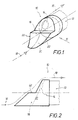
- FIGS 1 and 2 show an embodiment of the optronic ignition device 10 for a missile that is a rocket, a drone or can be an airplane.
- the optronic ignition device 10 has one Cut off indicated optics device 12 with a sensor window 14. With its sensor window 14, the optical device 12 is used to detect a fighting target.
- sensor window 14 is one Air deflector 16 associated with the air flow of the flying Keeps missile away from sensor window 14 and hurries past it. This is indicated by the dash-dotted line 18.
- the air deflection device 16 is designed as a spoiler nose 20, which extends from the Sensor window 14 or from the optic device 12 of the optronic Ignition device 10 is facing forward.
- the spoiler nose 20 is in the drawn embodiment with an inclined forward extending side edge contour 22 designed, which is stepped.
- the side edge contour 22 of the spoiler nose 20 cannot either graded or designed differently, i.e. to the aerodynamic Adapted to circumstances and e.g. be concave indented.
- the concave indentation can, for example, have the shape of a spherical surface. Through such a concavely indented inflow surface in the form of a spherical surface the air flow is kept away from sensor window 14 even when the Air flow does not flow parallel to the axis but at an angle.
Landscapes
- Engineering & Computer Science (AREA)
- General Engineering & Computer Science (AREA)
- Photometry And Measurement Of Optical Pulse Characteristics (AREA)
- Optical Radar Systems And Details Thereof (AREA)
- Aiming, Guidance, Guns With A Light Source, Armor, Camouflage, And Targets (AREA)
Abstract
Description
- Figur 1
- eine perspektivische Darstellung einer abschnittweise gezeichneten Ausbildung der optronischen Zündeinrichtung, und
- Figur 2
- eine Seitenansicht in Blickrichtung des Pfeiles II in Figur 1 auf die abschnittweise gezeichnete optronische Zündeinrichtung.
Claims (7)
- Optronische Zündeinrichtung für einen Flugkörper wie eine Drohne, eine Rakete oder ein Flugzeug, mit einem für seine Optikeinrichtung (12) vorgesehenen Sensorfenster (14),
dadurch gekennzeichnet, daß dem Sensorfenster (14) eine die Luftströmung (18) des fliegenden Flugkörpers am Sensorfenster (14) vorbeilenkende Luftablenkeinrichtung (16) zugeordnet ist. - Optronische Zündeinrichtung nach Anspruch 1,
dadurch gekennzeichnet, daß die Luftablenkeinrichtung (16) als eine Luft-Querströmung bewirkende Spoilernase (20) ausgebildet ist. - Optronische Zündeinrichtung nach Anspruch 2,
dadurch gekennzeichnet, daß die Spoilernase (20) gegen das Sensorfenster (14) radial versetzt vorgesehen ist.. - Optronische Zündeinrichtung nach Anspruch 2 oder 3,
dadurch gekennzeichnet, daß die Spoilernase eine nach vorne schräg geneigt verlaufende Seitenrandkontur (22) aufweist. - Optronische Zündeinrichtung nach Anspruch 4,
dadurch gekennzeichnet, daß die Spoilernase eine zylinderartig konkave Anströmfläche aufweist. - Optronische Zündeinrichtung nach Anspruch 5,
dadurch gekennzeichnet, daß die zylinderartig konkave Anströmfläche der Spoilernase konkav eingedellt kugeloberflächenförmig ausgebildet ist. - Optronische Zündeinrichtung nach einem der Ansprüche 4 bis 6,
dadurch gekennzeichnet, daß die Seitenrandkontur (22) der Spoilernase abgestuft ausgebildet ist.
Applications Claiming Priority (2)
| Application Number | Priority Date | Filing Date | Title |
|---|---|---|---|
| DE10031871 | 2000-06-30 | ||
| DE10031871A DE10031871B4 (de) | 2000-06-30 | 2000-06-30 | Schutzeinrichtung vor dem Sensor einer optoelektronischen Zündeinrichtung |
Publications (3)
| Publication Number | Publication Date |
|---|---|
| EP1167915A2 true EP1167915A2 (de) | 2002-01-02 |
| EP1167915A3 EP1167915A3 (de) | 2003-12-03 |
| EP1167915B1 EP1167915B1 (de) | 2008-02-13 |
Family
ID=7647336
Family Applications (1)
| Application Number | Title | Priority Date | Filing Date |
|---|---|---|---|
| EP01115256A Expired - Lifetime EP1167915B1 (de) | 2000-06-30 | 2001-06-23 | Optronische Zündeinrichtung für einen Flugkörper |
Country Status (3)
| Country | Link |
|---|---|
| US (1) | US20020000172A1 (de) |
| EP (1) | EP1167915B1 (de) |
| DE (2) | DE10031871B4 (de) |
Families Citing this family (2)
| Publication number | Priority date | Publication date | Assignee | Title |
|---|---|---|---|---|
| NL2022162B1 (en) * | 2018-12-10 | 2020-07-02 | Daf Trucks Nv | Camera system for mounting on a vehicle |
| EP4324751A1 (de) | 2022-08-18 | 2024-02-21 | Goodrich Lighting Systems GmbH & Co. KG | Schutzabdeckung für eine am rumpf montierte flugzeugaussenleuchte und flugzeugaussenleuchte |
Family Cites Families (5)
| Publication number | Priority date | Publication date | Assignee | Title |
|---|---|---|---|---|
| US2943572A (en) * | 1944-02-05 | 1960-07-05 | William J Flett | Fuze |
| GB2221020B (en) * | 1981-10-10 | 1990-12-12 | Ferranti Ltd | Missile including an optical proximity fuze sensor. |
| DE3615266A1 (de) * | 1986-05-06 | 1987-11-12 | Diehl Gmbh & Co | Abstandszuendeinrichtung |
| DE3927819A1 (de) * | 1989-08-23 | 1991-03-14 | Diehl Gmbh & Co | Optronischer zuender |
| DE4336335C2 (de) * | 1992-10-23 | 1996-11-07 | Daimler Benz Aerospace Ag | Schutzeinrichtung für Sensoren |
-
2000
- 2000-06-30 DE DE10031871A patent/DE10031871B4/de not_active Expired - Fee Related
-
2001
- 2001-06-23 EP EP01115256A patent/EP1167915B1/de not_active Expired - Lifetime
- 2001-06-23 DE DE50113578T patent/DE50113578D1/de not_active Expired - Fee Related
- 2001-06-28 US US09/894,027 patent/US20020000172A1/en not_active Abandoned
Also Published As
| Publication number | Publication date |
|---|---|
| EP1167915A3 (de) | 2003-12-03 |
| DE50113578D1 (de) | 2008-03-27 |
| EP1167915B1 (de) | 2008-02-13 |
| DE10031871A1 (de) | 2002-01-17 |
| US20020000172A1 (en) | 2002-01-03 |
| DE10031871B4 (de) | 2005-02-24 |
Similar Documents
| Publication | Publication Date | Title |
|---|---|---|
| DE60010701T2 (de) | Verfahren zum abwerfen von gegenmassnahmen und vorrichtung zum lagern und abwerfen von gegenmassnahmen | |
| EP1813907B1 (de) | Flugkörper für den Überschallbereich | |
| DE102010023938A1 (de) | Angetriebenes Fluggerät, insbesondere als Nurflügler und/oder mit geringer Radarsignatur ausgebildetes Fluggerät | |
| DE3609092A1 (de) | Geschoss fuer eine rohrwaffe zum bekaempfen aktiv und passiv reagierender sonderpanzerungen | |
| DE2458607A1 (de) | Flugziel mit radarverstaerkung | |
| EP0178467A1 (de) | Unbemannter Flugkörper mit einem Fallschirmbergesystem | |
| DE2452053A1 (de) | Einrichtung zum starten von raketengetriebenen flugkoerpern | |
| DE602005000222T2 (de) | Flugkörper zur Geländeaufklärung | |
| DE10031871A1 (de) | Optronische Zündeinrichtung für einen Flugkörper | |
| DE2428402A1 (de) | Einrichtung zum starten eines raketengetriebenen flugkoerpers | |
| DE102005042484B4 (de) | Unbemannter Gleitflugkörper | |
| EP3722736A1 (de) | Interventionssystem zur abwehr von ram-zielen und/oder uavs sowie verfahren zur abwehr von ram-zielen und/oder uavs | |
| DE1267100B (de) | Verfahren zur Bekaempfung von Bodenzielen | |
| DE102022004187A1 (de) | Vorrichtung und Verfahren zur Abwehr von fliegenden Objekten | |
| EP0187900B1 (de) | Unbemanntes Fluggerät für die Bekämpfung von Bodenzielen | |
| DE102019135246B4 (de) | Fluggerät und Verfahren zum Abfangen einer Drohne | |
| DE102006015952B4 (de) | Flugkörper für den Überschallbereich | |
| DE68907827T2 (de) | Geschoss zum neutralisieren einer zone, insbesondere eines flugplatzes. | |
| DE9320382U1 (de) | Selbstschutzanlage für Gefechtsfeldfahrzeuge | |
| DE19806066B4 (de) | Flugkörper gegen Reaktivpanzerung | |
| DE10211493B3 (de) | Absprengbare Abdeckhaube | |
| DE102023104248B3 (de) | Terminierungssystem zum Einleiten eines Absturzes eines Luftfahrzeugs | |
| DE69202723T2 (de) | Schockdämpfer für ein Strahlantriebssystem. | |
| DE2143689C3 (de) | Selbstgetriebener, von einem Trägerflugzeug gestarteter Flugkörper, dessen Startrichtung entgegengesetzt zur Flugrichtung des Trägerflugzeuges ist | |
| DE60221746T2 (de) | Verfahren zum Trennen eines selbstangetriebenen Flugkörper von seinem Träger |
Legal Events
| Date | Code | Title | Description |
|---|---|---|---|
| PUAI | Public reference made under article 153(3) epc to a published international application that has entered the european phase |
Free format text: ORIGINAL CODE: 0009012 |
|
| AK | Designated contracting states |
Kind code of ref document: A2 Designated state(s): AT BE CH CY DE DK ES FI FR GB GR IE IT LI LU MC NL PT SE TR |
|
| AX | Request for extension of the european patent |
Free format text: AL;LT;LV;MK;RO;SI |
|
| PUAL | Search report despatched |
Free format text: ORIGINAL CODE: 0009013 |
|
| AK | Designated contracting states |
Kind code of ref document: A3 Designated state(s): AT BE CH CY DE DK ES FI FR GB GR IE IT LI LU MC NL PT SE TR |
|
| AX | Request for extension of the european patent |
Extension state: AL LT LV MK RO SI |
|
| 17P | Request for examination filed |
Effective date: 20031105 |
|
| AKX | Designation fees paid |
Designated state(s): DE FI FR GB |
|
| RAP1 | Party data changed (applicant data changed or rights of an application transferred) |
Owner name: DIEHL BGT DEFENCE GMBH & CO.KG |
|
| GRAP | Despatch of communication of intention to grant a patent |
Free format text: ORIGINAL CODE: EPIDOSNIGR1 |
|
| GRAS | Grant fee paid |
Free format text: ORIGINAL CODE: EPIDOSNIGR3 |
|
| GRAA | (expected) grant |
Free format text: ORIGINAL CODE: 0009210 |
|
| AK | Designated contracting states |
Kind code of ref document: B1 Designated state(s): DE FI FR GB |
|
| REG | Reference to a national code |
Ref country code: GB Ref legal event code: FG4D Free format text: NOT ENGLISH |
|
| REF | Corresponds to: |
Ref document number: 50113578 Country of ref document: DE Date of ref document: 20080327 Kind code of ref document: P |
|
| ET | Fr: translation filed | ||
| PLBE | No opposition filed within time limit |
Free format text: ORIGINAL CODE: 0009261 |
|
| STAA | Information on the status of an ep patent application or granted ep patent |
Free format text: STATUS: NO OPPOSITION FILED WITHIN TIME LIMIT |
|
| 26N | No opposition filed |
Effective date: 20081114 |
|
| GBPC | Gb: european patent ceased through non-payment of renewal fee |
Effective date: 20080623 |
|
| PG25 | Lapsed in a contracting state [announced via postgrant information from national office to epo] |
Ref country code: FI Free format text: LAPSE BECAUSE OF NON-PAYMENT OF DUE FEES Effective date: 20080623 |
|
| REG | Reference to a national code |
Ref country code: FR Ref legal event code: ST Effective date: 20090228 |
|
| PG25 | Lapsed in a contracting state [announced via postgrant information from national office to epo] |
Ref country code: DE Free format text: LAPSE BECAUSE OF NON-PAYMENT OF DUE FEES Effective date: 20090101 |
|
| PG25 | Lapsed in a contracting state [announced via postgrant information from national office to epo] |
Ref country code: GB Free format text: LAPSE BECAUSE OF NON-PAYMENT OF DUE FEES Effective date: 20080623 |
|
| PG25 | Lapsed in a contracting state [announced via postgrant information from national office to epo] |
Ref country code: FR Free format text: LAPSE BECAUSE OF NON-PAYMENT OF DUE FEES Effective date: 20080630 |