EP1167299A1 - Apparatus and method for hydrothermal electrolysis - Google Patents
Apparatus and method for hydrothermal electrolysis Download PDFInfo
- Publication number
- EP1167299A1 EP1167299A1 EP00902905A EP00902905A EP1167299A1 EP 1167299 A1 EP1167299 A1 EP 1167299A1 EP 00902905 A EP00902905 A EP 00902905A EP 00902905 A EP00902905 A EP 00902905A EP 1167299 A1 EP1167299 A1 EP 1167299A1
- Authority
- EP
- European Patent Office
- Prior art keywords
- influent
- side walls
- conductive particles
- reaction
- reaction cell
- Prior art date
- Legal status (The legal status is an assumption and is not a legal conclusion. Google has not performed a legal analysis and makes no representation as to the accuracy of the status listed.)
- Ceased
Links
Images




Classifications
-
- C—CHEMISTRY; METALLURGY
- C02—TREATMENT OF WATER, WASTE WATER, SEWAGE, OR SLUDGE
- C02F—TREATMENT OF WATER, WASTE WATER, SEWAGE, OR SLUDGE
- C02F1/00—Treatment of water, waste water, or sewage
- C02F1/46—Treatment of water, waste water, or sewage by electrochemical methods
- C02F1/461—Treatment of water, waste water, or sewage by electrochemical methods by electrolysis
- C02F1/467—Treatment of water, waste water, or sewage by electrochemical methods by electrolysis by electrochemical disinfection; by electrooxydation or by electroreduction
- C02F1/4672—Treatment of water, waste water, or sewage by electrochemical methods by electrolysis by electrochemical disinfection; by electrooxydation or by electroreduction by electrooxydation
-
- B—PERFORMING OPERATIONS; TRANSPORTING
- B01—PHYSICAL OR CHEMICAL PROCESSES OR APPARATUS IN GENERAL
- B01D—SEPARATION
- B01D53/00—Separation of gases or vapours; Recovering vapours of volatile solvents from gases; Chemical or biological purification of waste gases, e.g. engine exhaust gases, smoke, fumes, flue gases, aerosols
- B01D53/32—Separation of gases or vapours; Recovering vapours of volatile solvents from gases; Chemical or biological purification of waste gases, e.g. engine exhaust gases, smoke, fumes, flue gases, aerosols by electrical effects other than those provided for in group B01D61/00
-
- B—PERFORMING OPERATIONS; TRANSPORTING
- B01—PHYSICAL OR CHEMICAL PROCESSES OR APPARATUS IN GENERAL
- B01D—SEPARATION
- B01D53/00—Separation of gases or vapours; Recovering vapours of volatile solvents from gases; Chemical or biological purification of waste gases, e.g. engine exhaust gases, smoke, fumes, flue gases, aerosols
- B01D53/34—Chemical or biological purification of waste gases
- B01D53/74—General processes for purification of waste gases; Apparatus or devices specially adapted therefor
- B01D53/77—Liquid phase processes
-
- B—PERFORMING OPERATIONS; TRANSPORTING
- B01—PHYSICAL OR CHEMICAL PROCESSES OR APPARATUS IN GENERAL
- B01J—CHEMICAL OR PHYSICAL PROCESSES, e.g. CATALYSIS OR COLLOID CHEMISTRY; THEIR RELEVANT APPARATUS
- B01J10/00—Chemical processes in general for reacting liquid with gaseous media other than in the presence of solid particles, or apparatus specially adapted therefor
-
- B—PERFORMING OPERATIONS; TRANSPORTING
- B01—PHYSICAL OR CHEMICAL PROCESSES OR APPARATUS IN GENERAL
- B01J—CHEMICAL OR PHYSICAL PROCESSES, e.g. CATALYSIS OR COLLOID CHEMISTRY; THEIR RELEVANT APPARATUS
- B01J19/00—Chemical, physical or physico-chemical processes in general; Their relevant apparatus
- B01J19/18—Stationary reactors having moving elements inside
-
- B—PERFORMING OPERATIONS; TRANSPORTING
- B01—PHYSICAL OR CHEMICAL PROCESSES OR APPARATUS IN GENERAL
- B01J—CHEMICAL OR PHYSICAL PROCESSES, e.g. CATALYSIS OR COLLOID CHEMISTRY; THEIR RELEVANT APPARATUS
- B01J19/00—Chemical, physical or physico-chemical processes in general; Their relevant apparatus
- B01J19/26—Nozzle-type reactors, i.e. the distribution of the initial reactants within the reactor is effected by their introduction or injection through nozzles
-
- B—PERFORMING OPERATIONS; TRANSPORTING
- B01—PHYSICAL OR CHEMICAL PROCESSES OR APPARATUS IN GENERAL
- B01J—CHEMICAL OR PHYSICAL PROCESSES, e.g. CATALYSIS OR COLLOID CHEMISTRY; THEIR RELEVANT APPARATUS
- B01J3/00—Processes of utilising sub-atmospheric or super-atmospheric pressure to effect chemical or physical change of matter; Apparatus therefor
- B01J3/04—Pressure vessels, e.g. autoclaves
-
- C—CHEMISTRY; METALLURGY
- C02—TREATMENT OF WATER, WASTE WATER, SEWAGE, OR SLUDGE
- C02F—TREATMENT OF WATER, WASTE WATER, SEWAGE, OR SLUDGE
- C02F1/00—Treatment of water, waste water, or sewage
- C02F1/46—Treatment of water, waste water, or sewage by electrochemical methods
- C02F1/461—Treatment of water, waste water, or sewage by electrochemical methods by electrolysis
-
- C—CHEMISTRY; METALLURGY
- C02—TREATMENT OF WATER, WASTE WATER, SEWAGE, OR SLUDGE
- C02F—TREATMENT OF WATER, WASTE WATER, SEWAGE, OR SLUDGE
- C02F1/00—Treatment of water, waste water, or sewage
- C02F1/46—Treatment of water, waste water, or sewage by electrochemical methods
- C02F1/461—Treatment of water, waste water, or sewage by electrochemical methods by electrolysis
- C02F1/46104—Devices therefor; Their operating or servicing
-
- C—CHEMISTRY; METALLURGY
- C02—TREATMENT OF WATER, WASTE WATER, SEWAGE, OR SLUDGE
- C02F—TREATMENT OF WATER, WASTE WATER, SEWAGE, OR SLUDGE
- C02F1/00—Treatment of water, waste water, or sewage
- C02F1/46—Treatment of water, waste water, or sewage by electrochemical methods
- C02F1/461—Treatment of water, waste water, or sewage by electrochemical methods by electrolysis
- C02F1/467—Treatment of water, waste water, or sewage by electrochemical methods by electrolysis by electrochemical disinfection; by electrooxydation or by electroreduction
-
- B—PERFORMING OPERATIONS; TRANSPORTING
- B01—PHYSICAL OR CHEMICAL PROCESSES OR APPARATUS IN GENERAL
- B01J—CHEMICAL OR PHYSICAL PROCESSES, e.g. CATALYSIS OR COLLOID CHEMISTRY; THEIR RELEVANT APPARATUS
- B01J2219/00—Chemical, physical or physico-chemical processes in general; Their relevant apparatus
- B01J2219/00049—Controlling or regulating processes
- B01J2219/00051—Controlling the temperature
- B01J2219/00054—Controlling or regulating the heat exchange system
-
- B—PERFORMING OPERATIONS; TRANSPORTING
- B01—PHYSICAL OR CHEMICAL PROCESSES OR APPARATUS IN GENERAL
- B01J—CHEMICAL OR PHYSICAL PROCESSES, e.g. CATALYSIS OR COLLOID CHEMISTRY; THEIR RELEVANT APPARATUS
- B01J2219/00—Chemical, physical or physico-chemical processes in general; Their relevant apparatus
- B01J2219/00049—Controlling or regulating processes
- B01J2219/00051—Controlling the temperature
- B01J2219/00054—Controlling or regulating the heat exchange system
- B01J2219/00056—Controlling or regulating the heat exchange system involving measured parameters
- B01J2219/00058—Temperature measurement
-
- B—PERFORMING OPERATIONS; TRANSPORTING
- B01—PHYSICAL OR CHEMICAL PROCESSES OR APPARATUS IN GENERAL
- B01J—CHEMICAL OR PHYSICAL PROCESSES, e.g. CATALYSIS OR COLLOID CHEMISTRY; THEIR RELEVANT APPARATUS
- B01J2219/00—Chemical, physical or physico-chemical processes in general; Their relevant apparatus
- B01J2219/00049—Controlling or regulating processes
- B01J2219/00051—Controlling the temperature
- B01J2219/00054—Controlling or regulating the heat exchange system
- B01J2219/00056—Controlling or regulating the heat exchange system involving measured parameters
- B01J2219/00058—Temperature measurement
- B01J2219/00063—Temperature measurement of the reactants
-
- B—PERFORMING OPERATIONS; TRANSPORTING
- B01—PHYSICAL OR CHEMICAL PROCESSES OR APPARATUS IN GENERAL
- B01J—CHEMICAL OR PHYSICAL PROCESSES, e.g. CATALYSIS OR COLLOID CHEMISTRY; THEIR RELEVANT APPARATUS
- B01J2219/00—Chemical, physical or physico-chemical processes in general; Their relevant apparatus
- B01J2219/00049—Controlling or regulating processes
- B01J2219/00051—Controlling the temperature
- B01J2219/00054—Controlling or regulating the heat exchange system
- B01J2219/00056—Controlling or regulating the heat exchange system involving measured parameters
- B01J2219/00069—Flow rate measurement
-
- B—PERFORMING OPERATIONS; TRANSPORTING
- B01—PHYSICAL OR CHEMICAL PROCESSES OR APPARATUS IN GENERAL
- B01J—CHEMICAL OR PHYSICAL PROCESSES, e.g. CATALYSIS OR COLLOID CHEMISTRY; THEIR RELEVANT APPARATUS
- B01J2219/00—Chemical, physical or physico-chemical processes in general; Their relevant apparatus
- B01J2219/00049—Controlling or regulating processes
- B01J2219/00051—Controlling the temperature
- B01J2219/00074—Controlling the temperature by indirect heating or cooling employing heat exchange fluids
- B01J2219/00087—Controlling the temperature by indirect heating or cooling employing heat exchange fluids with heat exchange elements outside the reactor
-
- B—PERFORMING OPERATIONS; TRANSPORTING
- B01—PHYSICAL OR CHEMICAL PROCESSES OR APPARATUS IN GENERAL
- B01J—CHEMICAL OR PHYSICAL PROCESSES, e.g. CATALYSIS OR COLLOID CHEMISTRY; THEIR RELEVANT APPARATUS
- B01J2219/00—Chemical, physical or physico-chemical processes in general; Their relevant apparatus
- B01J2219/00049—Controlling or regulating processes
- B01J2219/00051—Controlling the temperature
- B01J2219/00074—Controlling the temperature by indirect heating or cooling employing heat exchange fluids
- B01J2219/00087—Controlling the temperature by indirect heating or cooling employing heat exchange fluids with heat exchange elements outside the reactor
- B01J2219/00099—Controlling the temperature by indirect heating or cooling employing heat exchange fluids with heat exchange elements outside the reactor the reactor being immersed in the heat exchange medium
-
- B—PERFORMING OPERATIONS; TRANSPORTING
- B01—PHYSICAL OR CHEMICAL PROCESSES OR APPARATUS IN GENERAL
- B01J—CHEMICAL OR PHYSICAL PROCESSES, e.g. CATALYSIS OR COLLOID CHEMISTRY; THEIR RELEVANT APPARATUS
- B01J2219/00—Chemical, physical or physico-chemical processes in general; Their relevant apparatus
- B01J2219/00049—Controlling or regulating processes
- B01J2219/00051—Controlling the temperature
- B01J2219/00074—Controlling the temperature by indirect heating or cooling employing heat exchange fluids
- B01J2219/00087—Controlling the temperature by indirect heating or cooling employing heat exchange fluids with heat exchange elements outside the reactor
- B01J2219/00103—Controlling the temperature by indirect heating or cooling employing heat exchange fluids with heat exchange elements outside the reactor in a heat exchanger separate from the reactor
-
- B—PERFORMING OPERATIONS; TRANSPORTING
- B01—PHYSICAL OR CHEMICAL PROCESSES OR APPARATUS IN GENERAL
- B01J—CHEMICAL OR PHYSICAL PROCESSES, e.g. CATALYSIS OR COLLOID CHEMISTRY; THEIR RELEVANT APPARATUS
- B01J2219/00—Chemical, physical or physico-chemical processes in general; Their relevant apparatus
- B01J2219/00049—Controlling or regulating processes
- B01J2219/00051—Controlling the temperature
- B01J2219/00132—Controlling the temperature using electric heating or cooling elements
-
- B—PERFORMING OPERATIONS; TRANSPORTING
- B01—PHYSICAL OR CHEMICAL PROCESSES OR APPARATUS IN GENERAL
- B01J—CHEMICAL OR PHYSICAL PROCESSES, e.g. CATALYSIS OR COLLOID CHEMISTRY; THEIR RELEVANT APPARATUS
- B01J2219/00—Chemical, physical or physico-chemical processes in general; Their relevant apparatus
- B01J2219/00049—Controlling or regulating processes
- B01J2219/00051—Controlling the temperature
- B01J2219/00132—Controlling the temperature using electric heating or cooling elements
- B01J2219/00135—Electric resistance heaters
-
- B—PERFORMING OPERATIONS; TRANSPORTING
- B01—PHYSICAL OR CHEMICAL PROCESSES OR APPARATUS IN GENERAL
- B01J—CHEMICAL OR PHYSICAL PROCESSES, e.g. CATALYSIS OR COLLOID CHEMISTRY; THEIR RELEVANT APPARATUS
- B01J2219/00—Chemical, physical or physico-chemical processes in general; Their relevant apparatus
- B01J2219/00049—Controlling or regulating processes
- B01J2219/00051—Controlling the temperature
- B01J2219/0015—Controlling the temperature by thermal insulation means
- B01J2219/00155—Controlling the temperature by thermal insulation means using insulating materials or refractories
-
- B—PERFORMING OPERATIONS; TRANSPORTING
- B01—PHYSICAL OR CHEMICAL PROCESSES OR APPARATUS IN GENERAL
- B01J—CHEMICAL OR PHYSICAL PROCESSES, e.g. CATALYSIS OR COLLOID CHEMISTRY; THEIR RELEVANT APPARATUS
- B01J2219/00—Chemical, physical or physico-chemical processes in general; Their relevant apparatus
- B01J2219/00049—Controlling or regulating processes
- B01J2219/00051—Controlling the temperature
- B01J2219/00157—Controlling the temperature by means of a burner
-
- B—PERFORMING OPERATIONS; TRANSPORTING
- B01—PHYSICAL OR CHEMICAL PROCESSES OR APPARATUS IN GENERAL
- B01J—CHEMICAL OR PHYSICAL PROCESSES, e.g. CATALYSIS OR COLLOID CHEMISTRY; THEIR RELEVANT APPARATUS
- B01J2219/00—Chemical, physical or physico-chemical processes in general; Their relevant apparatus
- B01J2219/00049—Controlling or regulating processes
- B01J2219/00051—Controlling the temperature
- B01J2219/00159—Controlling the temperature controlling multiple zones along the direction of flow, e.g. pre-heating and after-cooling
-
- B—PERFORMING OPERATIONS; TRANSPORTING
- B01—PHYSICAL OR CHEMICAL PROCESSES OR APPARATUS IN GENERAL
- B01J—CHEMICAL OR PHYSICAL PROCESSES, e.g. CATALYSIS OR COLLOID CHEMISTRY; THEIR RELEVANT APPARATUS
- B01J2219/00—Chemical, physical or physico-chemical processes in general; Their relevant apparatus
- B01J2219/00049—Controlling or regulating processes
- B01J2219/00162—Controlling or regulating processes controlling the pressure
-
- B—PERFORMING OPERATIONS; TRANSPORTING
- B01—PHYSICAL OR CHEMICAL PROCESSES OR APPARATUS IN GENERAL
- B01J—CHEMICAL OR PHYSICAL PROCESSES, e.g. CATALYSIS OR COLLOID CHEMISTRY; THEIR RELEVANT APPARATUS
- B01J2219/00—Chemical, physical or physico-chemical processes in general; Their relevant apparatus
- B01J2219/00049—Controlling or regulating processes
- B01J2219/00164—Controlling or regulating processes controlling the flow
-
- B—PERFORMING OPERATIONS; TRANSPORTING
- B01—PHYSICAL OR CHEMICAL PROCESSES OR APPARATUS IN GENERAL
- B01J—CHEMICAL OR PHYSICAL PROCESSES, e.g. CATALYSIS OR COLLOID CHEMISTRY; THEIR RELEVANT APPARATUS
- B01J2219/00—Chemical, physical or physico-chemical processes in general; Their relevant apparatus
- B01J2219/00049—Controlling or regulating processes
- B01J2219/00182—Controlling or regulating processes controlling the level of reactants in the reactor vessel
-
- B—PERFORMING OPERATIONS; TRANSPORTING
- B01—PHYSICAL OR CHEMICAL PROCESSES OR APPARATUS IN GENERAL
- B01J—CHEMICAL OR PHYSICAL PROCESSES, e.g. CATALYSIS OR COLLOID CHEMISTRY; THEIR RELEVANT APPARATUS
- B01J2219/00—Chemical, physical or physico-chemical processes in general; Their relevant apparatus
- B01J2219/08—Processes employing the direct application of electric or wave energy, or particle radiation; Apparatus therefor
- B01J2219/0803—Processes employing the direct application of electric or wave energy, or particle radiation; Apparatus therefor employing electric or magnetic energy
- B01J2219/0805—Processes employing the direct application of electric or wave energy, or particle radiation; Apparatus therefor employing electric or magnetic energy giving rise to electric discharges
- B01J2219/0807—Processes employing the direct application of electric or wave energy, or particle radiation; Apparatus therefor employing electric or magnetic energy giving rise to electric discharges involving electrodes
- B01J2219/0824—Details relating to the shape of the electrodes
- B01J2219/0826—Details relating to the shape of the electrodes essentially linear
- B01J2219/083—Details relating to the shape of the electrodes essentially linear cylindrical
-
- B—PERFORMING OPERATIONS; TRANSPORTING
- B01—PHYSICAL OR CHEMICAL PROCESSES OR APPARATUS IN GENERAL
- B01J—CHEMICAL OR PHYSICAL PROCESSES, e.g. CATALYSIS OR COLLOID CHEMISTRY; THEIR RELEVANT APPARATUS
- B01J2219/00—Chemical, physical or physico-chemical processes in general; Their relevant apparatus
- B01J2219/08—Processes employing the direct application of electric or wave energy, or particle radiation; Apparatus therefor
- B01J2219/0873—Materials to be treated
- B01J2219/0881—Two or more materials
- B01J2219/0884—Gas-liquid
-
- B—PERFORMING OPERATIONS; TRANSPORTING
- B01—PHYSICAL OR CHEMICAL PROCESSES OR APPARATUS IN GENERAL
- B01J—CHEMICAL OR PHYSICAL PROCESSES, e.g. CATALYSIS OR COLLOID CHEMISTRY; THEIR RELEVANT APPARATUS
- B01J2219/00—Chemical, physical or physico-chemical processes in general; Their relevant apparatus
- B01J2219/18—Details relating to the spatial orientation of the reactor
- B01J2219/185—Details relating to the spatial orientation of the reactor vertical
-
- B—PERFORMING OPERATIONS; TRANSPORTING
- B01—PHYSICAL OR CHEMICAL PROCESSES OR APPARATUS IN GENERAL
- B01J—CHEMICAL OR PHYSICAL PROCESSES, e.g. CATALYSIS OR COLLOID CHEMISTRY; THEIR RELEVANT APPARATUS
- B01J2219/00—Chemical, physical or physico-chemical processes in general; Their relevant apparatus
- B01J2219/30—Details relating to random packing elements
- B01J2219/302—Basic shape of the elements
- B01J2219/30207—Sphere
-
- B—PERFORMING OPERATIONS; TRANSPORTING
- B01—PHYSICAL OR CHEMICAL PROCESSES OR APPARATUS IN GENERAL
- B01J—CHEMICAL OR PHYSICAL PROCESSES, e.g. CATALYSIS OR COLLOID CHEMISTRY; THEIR RELEVANT APPARATUS
- B01J2219/00—Chemical, physical or physico-chemical processes in general; Their relevant apparatus
- B01J2219/30—Details relating to random packing elements
- B01J2219/302—Basic shape of the elements
- B01J2219/30223—Cylinder
-
- C—CHEMISTRY; METALLURGY
- C02—TREATMENT OF WATER, WASTE WATER, SEWAGE, OR SLUDGE
- C02F—TREATMENT OF WATER, WASTE WATER, SEWAGE, OR SLUDGE
- C02F1/00—Treatment of water, waste water, or sewage
- C02F1/02—Treatment of water, waste water, or sewage by heating
-
- C—CHEMISTRY; METALLURGY
- C02—TREATMENT OF WATER, WASTE WATER, SEWAGE, OR SLUDGE
- C02F—TREATMENT OF WATER, WASTE WATER, SEWAGE, OR SLUDGE
- C02F1/00—Treatment of water, waste water, or sewage
- C02F1/02—Treatment of water, waste water, or sewage by heating
- C02F1/025—Thermal hydrolysis
-
- C—CHEMISTRY; METALLURGY
- C02—TREATMENT OF WATER, WASTE WATER, SEWAGE, OR SLUDGE
- C02F—TREATMENT OF WATER, WASTE WATER, SEWAGE, OR SLUDGE
- C02F1/00—Treatment of water, waste water, or sewage
- C02F1/46—Treatment of water, waste water, or sewage by electrochemical methods
- C02F1/461—Treatment of water, waste water, or sewage by electrochemical methods by electrolysis
- C02F1/46104—Devices therefor; Their operating or servicing
- C02F1/46109—Electrodes
- C02F1/46114—Electrodes in particulate form or with conductive and/or non conductive particles between them
-
- C—CHEMISTRY; METALLURGY
- C02—TREATMENT OF WATER, WASTE WATER, SEWAGE, OR SLUDGE
- C02F—TREATMENT OF WATER, WASTE WATER, SEWAGE, OR SLUDGE
- C02F1/00—Treatment of water, waste water, or sewage
- C02F1/72—Treatment of water, waste water, or sewage by oxidation
- C02F1/74—Treatment of water, waste water, or sewage by oxidation with air
-
- C—CHEMISTRY; METALLURGY
- C02—TREATMENT OF WATER, WASTE WATER, SEWAGE, OR SLUDGE
- C02F—TREATMENT OF WATER, WASTE WATER, SEWAGE, OR SLUDGE
- C02F1/00—Treatment of water, waste water, or sewage
- C02F1/46—Treatment of water, waste water, or sewage by electrochemical methods
- C02F1/461—Treatment of water, waste water, or sewage by electrochemical methods by electrolysis
- C02F1/46104—Devices therefor; Their operating or servicing
- C02F1/46109—Electrodes
- C02F2001/46133—Electrodes characterised by the material
-
- C—CHEMISTRY; METALLURGY
- C02—TREATMENT OF WATER, WASTE WATER, SEWAGE, OR SLUDGE
- C02F—TREATMENT OF WATER, WASTE WATER, SEWAGE, OR SLUDGE
- C02F2101/00—Nature of the contaminant
- C02F2101/30—Organic compounds
- C02F2101/36—Organic compounds containing halogen
-
- C—CHEMISTRY; METALLURGY
- C02—TREATMENT OF WATER, WASTE WATER, SEWAGE, OR SLUDGE
- C02F—TREATMENT OF WATER, WASTE WATER, SEWAGE, OR SLUDGE
- C02F2103/00—Nature of the water, waste water, sewage or sludge to be treated
- C02F2103/18—Nature of the water, waste water, sewage or sludge to be treated from the purification of gaseous effluents
-
- C—CHEMISTRY; METALLURGY
- C02—TREATMENT OF WATER, WASTE WATER, SEWAGE, OR SLUDGE
- C02F—TREATMENT OF WATER, WASTE WATER, SEWAGE, OR SLUDGE
- C02F2103/00—Nature of the water, waste water, sewage or sludge to be treated
- C02F2103/26—Nature of the water, waste water, sewage or sludge to be treated from the processing of plants or parts thereof
- C02F2103/28—Nature of the water, waste water, sewage or sludge to be treated from the processing of plants or parts thereof from the paper or cellulose industry
-
- C—CHEMISTRY; METALLURGY
- C02—TREATMENT OF WATER, WASTE WATER, SEWAGE, OR SLUDGE
- C02F—TREATMENT OF WATER, WASTE WATER, SEWAGE, OR SLUDGE
- C02F2201/00—Apparatus for treatment of water, waste water or sewage
- C02F2201/46—Apparatus for electrochemical processes
- C02F2201/461—Electrolysis apparatus
- C02F2201/46105—Details relating to the electrolytic devices
- C02F2201/4612—Controlling or monitoring
-
- C—CHEMISTRY; METALLURGY
- C02—TREATMENT OF WATER, WASTE WATER, SEWAGE, OR SLUDGE
- C02F—TREATMENT OF WATER, WASTE WATER, SEWAGE, OR SLUDGE
- C02F2201/00—Apparatus for treatment of water, waste water or sewage
- C02F2201/46—Apparatus for electrochemical processes
- C02F2201/461—Electrolysis apparatus
- C02F2201/46105—Details relating to the electrolytic devices
- C02F2201/46155—Heating or cooling
-
- C—CHEMISTRY; METALLURGY
- C02—TREATMENT OF WATER, WASTE WATER, SEWAGE, OR SLUDGE
- C02F—TREATMENT OF WATER, WASTE WATER, SEWAGE, OR SLUDGE
- C02F2301/00—General aspects of water treatment
- C02F2301/06—Pressure conditions
- C02F2301/066—Overpressure, high pressure
-
- C—CHEMISTRY; METALLURGY
- C02—TREATMENT OF WATER, WASTE WATER, SEWAGE, OR SLUDGE
- C02F—TREATMENT OF WATER, WASTE WATER, SEWAGE, OR SLUDGE
- C02F2301/00—General aspects of water treatment
- C02F2301/08—Multistage treatments, e.g. repetition of the same process step under different conditions
Definitions
- the present invention relates to apparatus and processes for performing hydrothermal reaction and electrolysis at the same time.
- hydrothermal electrolysis means that hydrothermal reaction and electrolysis are performed at the same time.
- a large amount of influent containing reducible substances such as organics (including synthetic polymers) and ammonia, eg, organic waste liquors or various industrial waste liquors containing a halide ion can be continuously treated.
- hydrothermal electrolysis In hydrothermal electrolysis, a closed pressure-resistant vessel is typically used as a reaction vessel because a high pressure environment is required. Thus, a batch process or a semi-continuous or continuous process consisting of repeated batch processes is applied when waste liquor is to be clarified by hydrothermal electrolysis.
- an object of the present invention is to provide a hydrothermal electrolytic apparatus capable of efficiency and continuously treating a large amount of waste liquor.
- An aspect of the present invention provides a hydrothermal electrolytic apparatus comprising a reaction cell for electrolyzing an influent containing water and reducible substances at high temperature and high pressure, wherein said reaction cell defines a chamber and has a pair of electrodes and the overall surface area of said pair of electrodes exposed in said chamber per 1 m 3 of the volume of said chamber in said reaction cell is 0.05 m 2 or more.
- the hydrothermal electrolytic apparatus of the present invention has an inlet at the bottom of the reaction cell for introducing an influent and an outlet at the top for discharging an effluent. This facilitates continuous treatment of influents.
- said reaction cell comprises two or more tubular reaction cells each having a metal inner wall serving as a cathode, and an anode is provided in each of said reaction cell.
- the anode and the cathode can form said pair of electrodes.
- said pair of electrodes preferably have a first electrode having two or more concentrically cylindrical first side walls and a first connecting member for connecting said first side walls together, and a second electrode having two or more concentrically cylindrical second side walls and a second connecting member for connecting said second side walls together, wherein said first side walls of said first electrode and said second side walls of said second electrode are alternately arranged to form a channel for influent between said first side walls and said second side walls.
- the hydrothermal electrolytic apparatus of the present invention preferably further has a high-pressure pump, an influent line for supplying influent to said reaction cell, an oxidizer line for supplying an oxidizer to said reaction cell, and an effluent line for discharging effluent from said reaction cell.
- Another aspect of the present invention provides a process for preparing clarified water, comprising the steps of introducing an influent containing water and reducible substances into a reaction cell of said hydrothermal electrolytic apparatus, supplying a direct current into said reaction cell at a temperature of 100°C or more but the critical temperature of said influent or less and at a pressure that allows water in said influent to be kept in the liquid phase, and discharging an effluent from said reaction cell.
- This clarified water may be recycled to another process or discharged to the environment.
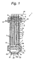
- Fig. 1 is a longitudinal sectional view showing the inner structure of reaction vessel 1 forming the core of the hydrothermal electrolytic apparatus according to a first embodiment of the present invention
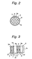
- Fig. 2 is a widthwise sectional view showing the inner structure of the reaction vessel.
- Fig. 3 is an enlarged sectional view of B in Fig. 1.
- Fig. 4 is an enlarged sectional view of C in Fig. 2.
- Fig. 4 shows a section of the part at which a spacer 43 is provided.
- the hydrothermal electrolytic apparatus comprises a reaction cell 31 for electrolyzing an influent containing water at high temperature and high pressure.
- Reaction cell 31 defines chambers 7 and has a pair of electrodes 31a, 41.
- the inner face of reaction cell 31 can serve as electrode 31a.
- the overall surface area of a pair of electrodes 31a, 41 exposed in chamber 7 in reaction cell 31 per 1 m 3 of the volume of the chamber is 0.05 m 2 or more, preferably 0.1 m 2 or more, more preferably 0.2 m 2 or more.
- the "overall surface area of electrodes" here means the effective surface area of electrodes substantially participating in electrolytic reaction.
- the reaction cell consists of two or more tubular reaction cells 31.
- Each of reaction cells 31 has a metal inner wall 31a serving as a cathode and a discharge electrode 41 serving as an anode is provided in each of said reaction cells 31.
- the first embodiment of the present invention comprises a reaction vessel 1.
- Reaction vessel 1 comprises a lower vessel part 2, a middle vessel part 3 and an upper vessel part 4.
- Lower vessel part 2 comprises an inlet 21 for introducing influent, an oxidizer inlet 22 for introducing an oxidizer, and a mixing chamber 23 for mixing the influent introduced from inlet 21 with the oxidizer introduced from oxidizer inlet 22.
- Middle vessel part 3 comprises reaction cells 31 in which the influent mixed with an oxidizer is electrolyzed under pressure and heating.
- Upper vessel part 4 comprises a current feed terminal 42 corresponding to each reaction cell 31.
- Current feed terminal 42 preferably has an insulating member from reaction vessel 1.
- Each current feed terminal 42 has a discharge electrode 41 extending to the inside of reaction cell 31.
- reaction vessel 1 as a whole forms a pressure-resistant vessel.
- Each of inlet 21 and oxidizer inlet 22 is singly provided in a wall portion 2a on the bottom of lower vessel part 2.
- Inlet 21 is connected to an influent line and oxidizer inlet 22 is connected to an oxidizer line.
- Mixing chamber 23 is partitioned by a dispersion plate 24 and contains a stirrer 25 therein.
- Dispersion plate 24 may be any known means for mixing the influent by disturbing the flow.
- Stirrer 25 is a common type having stirring blades 25a and used to help mixing and connected to a motor not shown.
- an introducing chamber 6 for smoothly introducing the influent mixed with an oxidizer in mixing chamber 23 into reaction cell 31.
- Wall 3a of middle vessel part 3 is connected to a negative line 32, which is in turn connected to a negative terminal not shown of a do source at constant current and voltage.
- reaction cell 31 is electrically connected with wall 3a of middle vessel part 3.
- a stainless steel tube may be welded to a stainless steel middle vessel part 3.
- the entire inner face 31a of reaction cell 31 serves as a cathode.
- Reaction cell 31 may be integrally formed with middle vessel part 3 or separately formed and fitted or otherwise incorporated into it.
- the inner face 31a of reaction cell 31 serves as a negative electrode to prevent corrosion by electrolysis.
- Discharge electrode 41 is in the form of a rod having a diameter smaller than the inner diameter of reaction cell 31 and arranged at a predetermined position in such a manner that each one may be inserted into each reaction cell 31.
- the discharge electrode may be a cylindrically shaped mesh or net or a cylinder having an axial hollow.
- the distance between the anode and the cathode is preferably equal. If this distance varies, an excessive current flows locally at narrow regions to accelerate deterioration of the anode at those regions.
- inner wall 31a of reaction cell 31 preferably has a cylindrical shape.
- the outer peripheral face of discharge electrode 41 also has a cylindrical shape so that the center axis of discharge electrode 41 substantially coincides with the center axis of inner wall 31a of reaction cell 31.
- Insulating spacer 43 At an end of discharge electrode 41 is provided an insulating spacer 43 to prevent any contact with the inner face of reaction cell 31.
- Insulating spacer 43 is preferably formed to suit the shape of the outer surface of discharge electrode 41 and the shape of the inner face of reaction cell 31.
- Insulating spacer 43 preferably has a through hole that allows the influent to pass.
- a chamber 7 is formed between the inner face of reaction cell 31 and discharge electrode 41 and connected to a discharge channel 8 formed at the connection between middle vessel part 3 and upper vessel part 4.
- Discharge channel 8 is connected to an outlet 34 at the upper end of middle vessel part 4 for discharging effluent from reaction vessel 1.
- the reaction vessel in the hydrothermal electrolytic apparatus has an inlet at the bottom for introducing an influent and an outlet at the top for discharging an effluent. This makes it easier to continuously hydrothermally electrolyze an influent.
- the reaction vessel has a plurality of rod-like discharge electrodes and the same number of reaction cells.
- the "volume of the chamber in the reaction cell” does not include the volume of discharge electrode 41 in reaction cell 31 but means the volume of the part where an influent is electrolyzed at high temperature and high pressure. In this embodiment, it specifically means the volume of chamber 7 located between electrodes 31a, 41 in reaction cell 31.
- the "overall surface area of a pair of electrodes exposed in the chamber” means the total of the surface area of electrode 31a and the surface area of discharge electrode 41 exposed in chamber 7. This excludes the area of discharge electrode 41 not exposed in chamber 7, eg, the surface area of the part of the discharge electrode located within upper vessel part 4 or the surface area of the part of the discharge electrode exposed in discharge channel 8 because these parts do not participate in the electrolysis of an influent.
- Each member can be formed from any material so far as middle vessel part 3 and reaction cell 31 should be formed from an electrically conductive material and the reaction vessel as a whole should be formed from a heat-resistant and pressure-resistant material.
- middle vessel part 3 and reaction cell 31 can be formed from stainless steel.
- Reaction cell 31 may have a multilayer structure comprising the innermost layer of an electrically conductive material such as stainless steel and the other layers of ceramics.
- the hydrothermal electrolytic apparatus according to this embodiment can be used as follows.
- An influent is heated up to a subcritical temperature and then introduced via inlet 21.
- an oxidizer such as oxygen-dissolved water is introduced via oxidizer inlet 22 and mixed with the influent in mixing chamber 23.
- the influent mixed with the oxidizer is forced upward under the pressure of successively introduced influent and oxidizer and inserted into reaction cell 31 via lower opening 31b of reaction cell 31.
- the influent introduced into reaction cell 31 is subjected to hydrothermal reaction and electrolytic oxidation reaction as it moves in chamber 7 so that reducible substances in the influent are degraded.
- the treated influent is introduced into discharge channel 8 via upper opening 31c and discharged from outlet 34.
- the effluent after treatment is introduced into various tanks as in known processes. In the apparatus according to this embodiment, a series of these reaction processes can be continuously performed.
- the hydrothermal electrolytic apparatus has the advantage that a large amount of influent can be treated because the reaction vessel has electrodes of a specific area as described above, which increases the throughput and advances a homogeneous reaction. Moreover, this embodiment allows a large amount of influent to be continuously treated even using a reaction vessel having an inlet at the bottom and an outlet at the top because said electrodes have a specific area. This embodiment also has the advantage that current feed terminals are easily mounted to improve workability.
- the apparatus of the present invention improves the efficiency of hydrothermal electrolytic reaction to effectively use the input energy and also reduces the size of the apparatus by increasing the surface area of electrodes per volume of chambers.
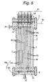
- Fig. 5 is a longitudinal sectional view showing the inner structure of the reaction vessel forming the core of the hydrothermal electrolytic apparatus according to a second embodiment of the present invention
- Fig. 6 is a widthwise sectional view showing the inner structure of the reaction vessel
- Fig. 7 is an enlarged sectional view of E in Fig. 5
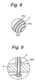
- Fig. 8 is an enlarged sectional view of F in Fig. 6
- Fig. 9 is an enlarged sectional view of G in Fig. 5.
- lower vessel part 2 has an influent inlet 21 at the center of the bottom, and a pipe 26 is connected to inlet 21 to extend upward from lower vessel part 2 to middle vessel part 3.
- Influent has been preliminarily mixed with an oxidizer in a mixer not shown, if desired.
- influent has been preliminarily heated up to a temperature of 100°C or more but the critical temperature or less.
- Middle vessel part 3 includes an anode 35a and a cathode 35b.
- Anode 35a first electrode
- cathode 35b second electrode
- cathode 35b second electrode
- Side walls 37a of anode 35a and side walls 37b of cathode 35b are alternately arranged to form a channel for influent between side walls 37a and 37b.
- pipe 26 is electrically connected to connecting member 36b to serve as cathode 35b.
- pipe 26 and the reaction vessel body can be protected against corrosion by cathodic protection.
- Both connecting members 36a, 36b are in the form of a disk and electrically conductive. Connecting member 36a fixes anode 35a to current feed terminals 42. Connecting member 36b fixes cathode 35b to lower vessel part 2.
- the hydrothermal electrolytic reactor has a concentrically cylindrical continuous reaction channel.
- the reaction channel is continuously provided from the center to the outer periphery of the reaction vessel so that influent flows from the center to the outer periphery of the reaction vessel.
- Upper vessel part 4 includes a plurality of current feed terminals 42. Upper vessel part 4 and current feed terminals 42 are electrically insulated from each other via an insulator 42a, as shown in Fig. 9.
- the "volume of chambers in the reaction cell” means the volume of the part where the influent is hydrothermally electrolyzed in middle vessel part 3.
- the "volume of chambers in the reaction cell” excludes the volume of anode 35a, the volume of cathode 35b and the volume defined by pipe 26.
- pipe 26 serves as a cathode
- radially outer channels of pipe 26 are included in the chamber.
- pipe 26 is not electrically conductive and does not serve as an electrode, however, radially outer channels of pipe 26 are not included in the chamber.
- influent is introduced from inlet 21 and transferred to the top of the reaction vessel through pipe 26, then transferred from the top to the bottom of the reaction vessel in the outer channel, then transferred from the bottom to the top in the subsequent outer channel, and so on. Thus, it is transferred successively from the center to the periphery of the reaction vessel. During then, reducible substances in the influent are oxidatively degraded by hydrothermal electrolysis. The treated influent is discharged from outlet 34 to the outside of reaction vessel 1.
- the apparatus according to this embodiment also has the advantage that the reaction channel can be longer to improve the efficiency of electrolysis. Thus, even low-concentration influents can be effectively treated.
- Hydrothermal electrolytic apparatus according to the first and second embodiments are not limited to the foregoing embodiments, but can be modified in various respects without departing from the spirit of the present invention.
- a mixing chamber having a stirrer was illustrated in the first embodiment, but the mixing chamber may not be necessary as shown in the second embodiment.
- the mixing chamber may not necessarily have a stirrer or a dispersion plate so far as the influent and oxidizer or the like are mixed.
- a heat-insulating material 39 may be filled outside reaction cell 31 in middle vessel part 3.
- reaction vessel may be thermally insulated by evacuation from a vacuum pump via a port formed in middle vessel part 3 instead of using an insulating material.
- the temperature may be kept by providing a heater 45 on the outer peripheral face of middle vessel part 3 as shown in Fig. 12.
- Ports 46 and 47 may be further provided in middle vessel part 3 as shown in Fig. 12.
- the temperature can be kept constant by directly heating the inside of middle vessel part 3 with a thermal fluid flown from port 46 into middle vessel part 3.
- the thermal fluid is discharged from port 47.
- the thermal fluid may be used not only for heating but also cooling.
- the discharge electrode or anode preferably has a surface having ruthenium, iridium, platinum, palladium, rhodium, tin or an oxide thereof or a ferrite.
- the discharge electrode itself may be made from these materials.
- the base material of the discharge electrode may be coated with these materials on the surface.
- Ruthenium, iridium, platinum, palladium, rhodium and tin may be elemental metals or oxides. Alloys of these metals are also preferably used. Such alloys include, for example, platinum-iridium, ruthenium-tin and ruthenium-titanium. These metals show high corrosion resistance, excellent insolubility for use as an anode. In some embodiments, especially preferred electrodes are based on palladium, ruthenium or an alloy of platinum and iridium.
- the current density at the surface of the anode is preferably 0.1 mA/dm 2 - 500 A/dm 2 . If the current density is higher than 500 A/dm 2 , the surface of the anode is liable to be exfoliated or dissolved. If the current density is lower than 0.1 mA/dm 2 , however, the area of the anode must be increased and the system becomes bulky.
- the current density is more preferably 10 mA/dm 2 - 100 A/dm 2 , most preferably 100 mA/dm 2 - 50 A/dm 2 . If a new material for the anode is developed, the current density at the anode can be further increased.
- an influent containing water and reducible substances can be treated to oxidatively degrade the reducible substances.
- Influents that can be treated by the present invention include various waste liquors.
- Reducible substances that can be degraded by the present invention include organics and ammonia.
- organics include aliphatic and aromatic hydrocarbons such as alkanes, alkenes, alkynes; alcohols; aldehydes; ketones; amines; carboxylic acids such as acetic acid; carboxylic acid derivatives such as esters, amides, anhydrides; halogenated hydrocarbons; phenols; sulfur-containing organic compounds such as sulfoxides, mercaptans, thiols, polysulfones; etc.
- Organics also include synthetic polymers such as polyolefins, polyesters or various engineering plastics.
- Influents preferably have fluidity, and may be any of suspension, emulsion, aqueous solution or slurry, but preferably suspension or slurry. Influents may contain liquid or solid reducible substances. Influents include suspensions of unprecipitable solid particles dispersed in water, emulsions of liquid particles dispersed in water, aqueous solutions of liquid organics or inorganics dissolved in water and mixtures thereof. For example, influents contain a continuous phase containing water, liquid organics and dissolved salts and a discontinuous phase containing solid organics such as particles, and optionally non-combustible solids such as ash.
- influents contain a strong acid ion.
- strong acid ions show an electrochemical catalytic effect to advance hydrothermal electrolytic reaction more efficiently.
- the strong acid ion may be an inorganic acid ion or an organic acid ion.
- the strong acid is preferably an inorganic acid ion because organic acid ions may be degraded as hydrothermal electrolysis proceeds.
- Suitable inorganic strong acid ions include, for example, halide ions, sulfate ion (SO 4 2- ), nitrate ion (NO 3 - ), phosphate ion (PO 4 3- ), among which halide ions are especially preferred.
- Suitable organic strong acid ions include, for example, trifluoroacetate ion (CF 3 COO - ).
- Suitable halide ions include chloride ion (Cl - ), bromide ion (Br - ), iodide ion (I - ) or any combination thereof, among which chloride ion or bromide ion is especially preferred.
- a halide ion-producing salt may be dissolved in the influent.
- a hydrohalic acid such as hydrogen chloride (HCl), hydrogen bromide (HBr) or hydrogen iodide (HI) may be contained in the influent.
- chloride ion moves to the aqueous phase to incorporate chloride ion as hydrothermal reaction proceeds.
- an oxidizer is preferably added to the influent to more efficiently advance hydrothermal electrolytic oxidation.
- Oxidizers that can be used in the present invention are oxygen gas, ozone gas, hydrogen peroxide and hypohalous acids, more preferably oxygen gas.
- Oxygen gas may be a gas containing oxygen gas, eg, air is preferably used.
- air can be bubbled into water or the like to dissolve oxygen, and the resulting oxygen-dissolved water can be introduced as an oxidizer via oxidizer inlet 22.
- compressed air can be introduced into reaction cell 23 to serve as an oxidizer.
- hydrothermal reaction takes place at a temperature of 100°C or more but the critical temperature of said influent or less and at a pressure that allows said influent to be kept in the liquid phase. Temperatures lower than 100°C are not preferred because the rate of hydrothermal reaction is lowered to extend the reaction time.
- the finding of the present invention cannot be directly applied for temperatures higher than the critical temperature because physical properties of aqueous medium significantly change. At the supercritical stage, for example, the solubility of the electrolyte greatly decreases and electric conductivity is decreased.
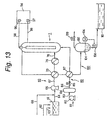
- Fig. 13 shows such an influent treatment system.
- an influent line 60 for supplying an influent is connected to a hydrothermal electrolytic reaction vessel 1 of the present invention.
- Influent line 60 preferably has a feed tank 61, a high-pressure pump 66, a heat exchanger 70 and a heater 74, and an influent can be transferred in this order.
- Hydrothermal electrolytic reaction vessel 1 may consist of a hydrothermal electrolytic reaction vessel according to the first embodiment, a hydrothermal electrolytic reaction vessel according to the second embodiment or the like.
- Feed tank 61 can hold an influent.
- a wastewater line 62 for introducing wastewater into feed tank 61 and a halide line 63 for supplying a halide ion source such as chloride ion (Cl - ) into feed tank 61.
- This halide ion source may be sea water.
- Halide line 63 can supply a halide ion such as chloride ion to feed tank 61 to control the halide ion level in the influent held in feed tank 61.
- Feed tank 61 can be connected to high-pressure pump 66 via line 64 to transfer an influent.
- a tap water line 68 for supplying tap water is preferably connected to line 64 so that tap water substantially free from reducible substances can be transiently flown when the hydrothermal electrolytic apparatus shown in Fig. 13 is started up or stopped.
- High-pressure pump 66 pressurizes the influent to a pressure required for hydrothermal reaction to force the influent into reaction vessel 1 under this pressure via heat exchanger 70 and heater 74.
- Influent line 60 preferably has heat exchanger 70.
- Heat exchanger 70 is connected to influent line 60 and effluent line 100 so that heat exchanger 70 changes heat between the influent flowing in influent line 60 and the effluent flowing in effluent line 100.
- the influent pressurized in high-pressure pump 66 is often at room temperature.
- the effluent discharged from reaction vessel 1 is kept at high temperature via hydrothermal reaction. Therefore, heat exchanger 70 heats the influent flowing in influent line 60 and cools the effluent flowing in effluent line 100. Even if the heat exchanger is not provided, only heat efficiency decreases.
- influent line 60 has a heater 74 for further heating the influent heated by heat exchanger 70.
- heater 74 heats the influent to a temperature required for hydrothermal reaction, for example.
- the temperature to which the influent is heated is determined taking into account the exothermic heat from the oxidation reaction and the exothermic heat from the electrolysis of reducible substances in reaction vessel 1.
- Another heater for heating the outside of reaction vessel 1 may be further provided.
- an oxidizer line 80 is preferably provided. Suitable oxidizers include gases containing oxygen gas such as air. Air is introduced into compressor 82 via line 81 and preferably pressurized from 1 MPa to 25 MPa, for example. This compressed air is introduced into accumulator 84 via line 83. Thus, compressor-induced pulsation of compressed air can be prevented.
- gases containing oxygen gas such as air. Air is introduced into compressor 82 via line 81 and preferably pressurized from 1 MPa to 25 MPa, for example. This compressed air is introduced into accumulator 84 via line 83. Thus, compressor-induced pulsation of compressed air can be prevented.
- a valve 85 for controlling the amount of compressed air, ie, the amount of oxidizer is provided downstream of accumulator 84.
- Compressed air is preheated in heat exchanger 87 and then introduced into reaction vessel 150 via line 188.
- Heat exchanger 187 heats compressed air and cools the effluent.
- a liquid such as water in which oxygen gas is dissolved may be introduced into reaction vessel 1.
- Oxidizers in the form of a gas such as oxygen gas (including air) have higher water-solubility at lower temperature or higher pressure. Therefore, an oxidizer in the form of a gas may be dissolved in water at low or room temperature under high pressure and then this cold water may be supplied to the reaction vessel.
- aqueous hydrogen peroxide, a hypochlorous acid or a solid oxidizer may be dissolved in water and supplied to the reaction vessel via a high-pressure pump or the like. When an oxidizer rich in water is added, an additional heater may be provided between high-pressure pump 86 and reaction vessel 1.
- oxidizer line 80 is directly connected to reaction vessel 1. If oxidizer line 80 is connected to influent line 60, line 76 between heater 74 and reaction vessel 50 will be susceptible to corrosion. On the another hand, when an oxidizer is directly introduced into reaction vessel 1, the inner wall of reaction vessel 1 can be protected from corrosion because the inner wall of reaction vessel 11 serves as a cathode of electrolysis.
- Reaction vessel 1 may consist of a reaction vessel according to the first or second embodiment as described above.
- reaction vessel 1 has an axially extending tubular shape, preferably a cylindrical shape.
- Positive terminal 96 and negative terminal 97 of dc source 94 are connected to the anode and the cathode of hydrothermal electrolytic apparatus 1 via lines 98, 99, respectively.
- an effluent line 100 for discharging the hydrothermally electrolyzed influent is connected to reaction vessel 1.
- effluent line 100 has heat exchangers 70/87, a gas-liquid separator 102, and an effluent tank 110, and the effluent hydrothermally electrolyzed in reaction vessel 1 can be transferred in this order.
- Heat exchangers 70/87 have already been explained.
- gas-liquid separator 102 is connected to effluent line 100.
- Gas-liquid separator 102 separates gas and liquid in the effluent.
- the effluent is held at a predetermined level 104 in gas-liquid separator 102.
- Pressure transmitter tube may be provided between the space above said level 104 and the effluent below said level 104, and a level detector, for determining the gas-liquid interface or slurry level, may be provided in this pressure transmitter tube.
- Level-detecting mechanism 106 may be designed to measure the level 104 by the pressure difference between gas and liquid to discharge the effluent in such a manner that said level 104 may be fixed or within a fixed range.
- Gas-liquid separator 102 may be provided with a piezoelectric element for converting pressure into an electric signal each above and below said level 104, whereby this electric signal is entered into a level detector to detect the pressure difference.
- gas-liquid separator 102 has a level-controlling mechanism 106 stabilizing the level of the effluent in gas-liquid separator 102 within a fixed range.
- Said level-controlling mechanism may have a level detector for detecting the pressure difference between gas and the effluent, a valve for discharging the effluent and a controller for controlling the valve by a signal from the level detector.
- the level-controlling mechanism may have a pressure transmitter tube or a piezoelectric element.
- a valve 108 is connected to gas-liquid separator 102 so that the effluent in gas-liquid separator 102 can be discharged into container 110 when valve 108 is opened.
- switching of valve 108 is controlled by a signal from level-controlling mechanism 106.
- Gas-liquid separator 102 may have a pressure controlling mechanism for controlling the pressure in the gas-liquid separator within a predetermined range.
- Said pressure controlling mechanism may have, for example, a pressure detector for detecting the pressure of the gas phase, a valve for discharging gas and a controller for controlling the valve by a signal from the pressure detector.
- the pressure-controlling mechanism controls the pressure in the range that the influent is kept at the liquid phase and reaction vessel 1 and gas-liquid separator 102 are safely operated, for example.
- the pressure detector may have a piezoelectric element.
- a valve 109 is connected to gas-liquid separator 102 so that the gas in gas-liquid separator 102 can be discharged to the atmosphere when valve 109 is opened.
- switching of valve 109 is controlled by a signal from a pressure-controlling mechanism not shown.
- tap water supply from the tap water line to influent line 60 is stopped and influent supply from feed tank 61 to influent line 60 is started.
- Halide ion level or other like of the influent are preliminarily controlled via halide line 63 or the like,
- the influent is introduced into reaction vessel 1 while heating of the influent is continued in heater 74.
- An oxidizer is introduced into reaction vessel 1 via oxidizer line 80.
- reaction vessel 1 After the influent and oxidizer are introduced into reaction vessel 1, electrolysis is started. Thus, dc source 94 is turned on to supply dc to the anode and cathode of hydrothermal electrolytic apparatus 1. The influent kept in the liquid phase under high temperature and high pressure moves in reaction vessel 1, during which hydrothermal reaction and electrolysis proceed at the same time. The heating temperature of heater 74 is appropriately lowered because heat is generated with hydrothermal reaction and electrolysis.
- the reaction time should be enough long for reducible substances in the influent to be oxidatively degraded, for example 1 second to 48 hours, preferably 1 minute to 24 hours.
- the reaction time is more preferably 5 hours or less, still more preferably 2 hours or less.
- the reaction time is adjusted in function of the volume of reaction vessel 1 and the feed flow rate of the influent.
- reaction vessel 1 When the reaction is to be stopped, the inflow from feed tank 61 to influent line 60 is stopped and tap water is introduced from the tap water line to influent line 60. Oxidizer supply from oxidizer line 80 into reaction vessel 1 is also stopped. Then, the do source is turned off to stop electrolysis. Then, the output of heater 74 is lowered so that the temperature of the influent flowing into reaction vessel 1 is gradually lowered.
- influent can be efficiently treated by hydrothermal electrolytic reaction by increasing the surface area of electrodes in hydrothermal electrolysis, as has been described above.
- the surface area of electrodes can be substantially increased by incorporating electrically conductive particles into the influent, preferably suspending electrically conductive particles into the influent so that the conductive particles present in the influent can substantially serve as an electrode during the electrolysis of the influent.
- the incorporation of electrically conductive particles into the influent means that the influent containing water and electrically conductive particles is located between the original cathode and the original anode in the hydrothermal electrolytic apparatus.
- a dc voltage is applied across the original cathode and the original anode
- individual conductive particles serve as an anode at the surfaces facing the original cathode and as a cathode at the surfaces facing the original anode under the effect of an electric field. Therefore, a current flows locally between the original cathode and the surfaces of individual conductive particles serving as an anode, and also a current flows locally between the original anode and the surfaces of conductive particles serving as a cathode.
- the current flowing between the original anode and the original cathode increases and the voltage across the original anode and the original cathode also increases when conductive particles exist in the influent as compared with when no conductive particles exist in the influent. Therefore, a large amount of electric power can be supplied to the influent to greatly improve the throughput and process efficiency of the hydrothermal electrolytic apparatus without increasing the surface area of the original anode and the original cathode.
- a third aspect of the present invention provides a hydrothermal electrolytic process comprising the step of subjecting an influent containing water, reducible substances and conductive particles to electrolysis at a temperature of 100°C or more but the critical temperature of said influent or less and at a pressure that allows water in said influent to be kept in the liquid phase.
- said conductive particles are suspended in said influent, and said influent preferably further contains a strong acid ion.
- said electrolysis step is followed by the step of separating said conductive particles and the step of adding the separated conductive particles to said influent again.
- Still another aspect of the present invention provides a hydrothermal electrolytic apparatus comprising a feeder for supplying an influent containing water and reducible substances with conductive particles, and a reaction cell for subjecting said influent supplied with conductive particles to electrolysis at a temperature of 100°C or more but the critical temperature of said influent or less and at a pressure that allows water in said influent to be kept in the liquid phase.
- said reaction cell preferably has a pair of electrodes, more preferably one of which serves as an anode and the other serves as a cathode.
- Still another aspect of the present invention provides a hydrothermal electrolytic apparatus comprising a reaction cell for supplying a direct current to an influent containing water, reducible substances and conductive particles at a temperature of 100°C or more but the critical temperature of said influent or less and at a pressure that allows water in said influent to be kept in the liquid phase, and a separator for separating the conductive particles from the effluent.
- said reaction cell has a pair of electrodes, more preferably one of which serves as an anode and the other serves as a cathode.
- said separator preferably comprises a liquid cyclone. Or said separator preferably comprises a filter device.
- the influent contains conductive particles.
- a do voltage is applied across the original cathode and the original anode in a hydrothermal electrolytic apparatus supplied with a influent containing conductive particles
- individual conductive particles serve as an anode at the surfaces facing the original cathode and as a cathode at the surfaces facing the original anode under the effect of an electric field. Therefore, a current flows locally between the original cathode and the surfaces of individual conductive particles serving as an anode, and also a current flows locally between the original anode and the surfaces of conductive particles serving as a cathode.
- conductive particles are suspended in the influent.
- solid conductive particles can flow with the influent. This also prevents conductive particles from adhering to the surface of electrodes.
- Conductive particles may be wholly formed of a conductive material. Alternatively, they may be particles of a conductive material coated with another conductive material on their surfaces or particles of a non-conductive material coated with a conductive material on their surfaces. Even particles having an insulating oxide or the like deposited on their surfaces by corrosion or other reasons are regarded as conductive particles so far as they are generally conductive.
- Particles formed of a conductive material include, for example, carbon particles, metal particles and conductive oxide particles.
- Carbon particles include, for example, particles of graphite.
- Metal particles include, for example, so-called metal powders such as iron powder, copper powder, silver powder, nickel powder, cobalt powder and aluminium powder.
- Conductive oxide particles include particles of a ferrite and ruthenium oxide. In terms of costs, iron powder and aluminium powder are preferred.
- Iron powder includes powdered scrap from machining of steel (including stainless steel), cast iron or the like.
- Particles of a conductive material coated with another conductive material include metal particles coated with a thin film of another metal on their surfaces such as copper particles coated with platinum on their surfaces.
- Particles of a non-conductive material coated with a conductive material on their surfaces include particles of an oxide powder coated with a metal thin film on their surfaces such as aluminium oxide particles coated with copper on their surfaces.
- Particles of a conductive or non-conductive oxide powder coated with a conductive oxide on their surfaces are also suitable, such as zirconium oxide particles coated with iridium oxide on their surfaces and silicon dioxide particles coated with ruthenium oxide on their surfaces.
- Synthetic polymer particles coated with a metal or a conductive oxide on their surfaces are also suitable, such as polymer particles of polyethylene glycol coated with ruthenium oxide on their surfaces.
- Means for coating a metal thin film include electroplating, electroless plating, sputtering, physical vapor deposition, chemical vapor deposition, etc.
- Means for coating a conductive oxide thin film include calcination, sputtering, physical vapor deposition, chemical vapor deposition, etc.
- conductive particles are subjected to a current in the presence of a strong acid ion such as a halide ion at high temperature and high pressure.
- Suitable conductive particles may be irreversible particles liable to be molten or corroded under these conditions or reusable chemically stable particles.
- iron powder, aluminium powder or the like are preferred in terms of costs.
- Reusable conductive particles preferably have such an excellent corrosion resistance that they remain insoluble even if a current is applied.
- Reusable conductive particles are preferably formed of or coated with a conductive material having ruthenium, iridium, platinum, palladium, rhodium, copper, nickel, tin or an oxide thereof or a ferrite.
- Ruthenium, iridium, platinum, palladium, rhodium, copper, nickel and tin may be elementary metals or oxides. Alloys of these metals are also preferably used. Such alloys include, for example, platinum-iridium, ruthenium-tin and ruthenium-titanium. In some embodiments, conductive materials based on palladium, ruthenium or an alloy of platinum and iridium are especially preferred.
- Conductive particles may be in any form such as, but not limited to, sphere, rod, disk, T-shape, donut, tube, fiber, etc. Hollow particles are also suitable.
- Conductive particles preferably have a size shorter than the distance between the anode and the cathode.
- the average size of conductive particles is preferably 1 cm or less, more preferably 5 mm or less, still more preferably 1 mm or less, most preferably 0.5 mm or less.
- the size of spherical conductive particles means their diameter.
- the size of rod-like or tubular conductive particles means their length.
- the size of conductive particles may be homogeneous or may widely vary.
- Rod-like or tubular conductive particles preferably have an aspect ratio, ie, the ratio of the length to the diameter of the rod or tube of 0.1-1000, more preferably 0.5-100.
- the influent preferably contains 0.01% by weight or more of conductive particles, more preferably 0.1% by weight or more of conductive particles.
- the presence of conductive particles in an amount even as small as 0.01% by weight in the influent increases a current, therefore a voltage across the original electrodes.
- the influent preferably contains 30% by weight or less of conductive particles, more preferably 10% by weight or less of conductive particles. If more than 30% by weight of conductive particles are contained, the fluidity of the influent is affected and the probability of a short circuit between electrodes significantly increases.
- the content of conductive particles in the influent means the content in the feed line for supplying the influent into the reaction cell. This is because conductive particles are not always uniformly distributed in the reaction cell so that the content is difficult to exactly determine.
- the concentration of conductive particles tends to be higher at the bottom of the reaction cell.
- influent line 60 for supplying an influent is connected to reaction vessel 50.
- Influent line 60 preferably has a feed tank 61, a high-pressure pump 66, a heat exchanger 70 and a heater 74, and an influent can be transferred in this order.
- a feeder 130 for supplying conductive particles to feed tank 61 is provided.
- Feeder 130 comprises a hopper 132 for holding conductive particles 138 and a screw feeder 134 for quantitatively supplying conductive particles 138 to feed tank 61.
- a motor 136 is connected to screw feeder 134.
- the screw of screw feeder 134 rotates with the rotation of motor 136 to introduce a metered amount of conductive particles 138 into feed tank 61.
- Hopper 132 may be supplied with crude conductive particles or conductive particles 112 separated by filter device 114.
- Feed tank 61 is equipped with a stirrer 61a for homogeneously agitating the influent.
- Each member on influent line 60 has the same operation as explained about Fig. 13, and is not explained here.
- an oxidizer line 80 is preferably provided. Each member on the oxidizer line also has the same operation as explained about Fig. 13, and is not explained here.
- reaction vessel 50 has an axially extending tubular shape, preferably a cylindrical shape.
- Reaction vessel 50 includes a pair of electrodes for electrolysis therein.
- Reaction vessel 50 has a metal inner wall 50s, which can serve as a cathode.
- the wall of reaction vessel 50 may be wholly made from a metal.
- Reaction vessel 50 contains a rod-like anode 92 therein.
- the outer face of anode 92 is also cylindrical so that the center axis of anode 92 substantially coincides with the center axis of reaction vessel 50.
- Anode 92 may be a cylindrically shaped mesh or net or a cylindrically shaped plate.
- Positive terminal 96 and negative terminal 97 of do source 94 are connected to anode 92 and cathode 50s via lines 98, 99, respectively.
- Line 98 for feeding the anode passes through the top 51b of reaction vessel 50, while line 98 is insulated from reaction vessel 50 by insulating member 56.
- line 99 may be directly connected to reaction vessel 50.
- Reaction vessel 50 may be heated by a heater not shown.
- the heater may be an electric heater, for example.
- the outside of the reaction vessel may be directly heated with a burner or the like.
- a recycle line 120 for recycling conductive particles is connected to the reaction vessel.
- Recycle line 120 comprises a separator 122 for separating conductive particles from the effluent.
- separator 122 for separating conductive particles from the effluent.
- a separator 122 for separating solid particles from the effluent is connected to the top of reaction vessel 50 via line 121.
- Separator 122 may consist of, for example, a liquid cyclone that centrifugally separates conductive particles. In the liquid cyclone, conductive particles settle at the bottom. In separator 122, all the conductive particles in the effluent may not be separated. Most of conductive particles may be removed in separator 122 and the remainder may be removed by filter device 110.
- Separator 122 is connected to pump 126 via line 124, and pump 126 is connected to the bottom of reaction vessel 50 via line 127.
- separator 122 consists of a liquid cyclone, a concentrated slurry containing conductive particles is obtained. This concentrated slurry can be introduced into the bottom of reaction vessel 50 by pump 126.
- An effluent line 100 for discharging the effluent deprived of at least a part of conductive particles is connected to separator 122.
- Effluent line 100 preferably has heat exchangers 87/70, a gas-liquid separator 102, and a filter device 110, and the effluent hydrothermally electrolyzed in reaction vessel 50 is transferred in this order.
- gas-liquid separator 102 is connected to effluent line 100.
- Gas-liquid separator 102 separates gas and liquid in the effluent.
- the effluent is held at a predetermined level 104 in gas-liquid separator 102.
- a pressure transmitter tube may be provided between the space above said level 104 and the effluent below said level 104, and a level detector for determining the gas-liquid interface or slurry level may be provided in this pressure transmitter tube.
- a level detecting mechanism not shown may be designed to measure the level 104 by the pressure difference between gas and liquid to discharge the effluent in such a manner that said level 104 may be fixed or within a fixed range.
- Gas-liquid separator 102 may be provided with a piezoelectric element for converting pressure into an electric signal each above and below said level 104, whereby this electric signal is entered into a level detector to detect the pressure difference.
- gas-liquid separator 102 has a level-controlling mechanism 106 stabilizing the level of the effluent in gas-liquid separator 102 within a fixed range.
- Said level-controlling mechanism may have a level detector for detecting the pressure difference between gas and the effluent, a valve for discharging the effluent and a controller for controlling the valve by a signal from the level detector.
- the level-controlling mechanism may have a pressure transmitter tube or a piezoelectric element.
- a valve 108 is connected to gas-liquid separator 102 so that the treated water in gas-liquid separator 102 can be discharged into filter device 114 when valve 108 is opened.
- switching of valve 108 is controlled by a signal from the level-controlling mechanism.
- Gas-liquid separator 102 may have a pressure controlling mechanism for controlling the pressure in the gas-liquid separator within a predetermined range.
- Said pressure controlling mechanism may have, for example, a pressure detector for detecting the pressure of the gas phase, a valve for discharging gas and a controller for controlling the valve by a signal from the pressure detector.
- the pressure-controlling mechanism preferably adjusts the pressure at a level that allows filter device 114 to accomplish smooth separation, for example.
- the pressure detector may have a piezoelectric element.
- a valve 109 is connected to gas-liquid separator 102 so that the gas in gas-liquid separator 102 can be discharged to the atmosphere when valve 109 is opened.
- switching of valve 109 is controlled by a signal from a pressure-controlling mechanism not shown.
- the pressure of gas-liquid separator 102 and the pressure of reaction vessel 50 are preferably separately controlled so that the pressure of reaction vessel 50 is adjusted at a pressure that allows a liquid phase to be kept in hydrothermal electrolysis and the pressure of gas-liquid separator 102 is adjusted at a pressure that allows dielectric particles to be smoothly filtered by filter device 114.
- a pressure-regulating valve 115 having a pressure sensor is separately provided on line 100 to control the pressure of reaction vessel 50.
- the pressure of reaction vessel 50 is kept on the inlet side of valve 115, so that the pressure of reaction vessel 50 can be controlled via valve 115.
- Filter device 114 filters the effluent to separate conductive particles 112 contained in the effluent.
- Filter device 114 may consist of a filter press, for example.
- the effluent deprived of conductive particles is stored in a container 116.
- these conductive particles 112 can be supplied to feeder 130 and recycled.
- Feeder 130 supplies a desired amount of conductive particles 138 to feed tank 61 to control the content of conductive particles in the influent.
- a halide ion source is introduced from halide line 63 or the like into feed tank 61 to control its content.
- the influent is homogenized under agitation with stirrer 61a.
- the influent in feed tank 61 is transferred by high-pressure pump 66, and the influent is preheated in heat exchanger 70 and further heated in heater 74, and then introduced into reaction vessel 50.
- compressed air serving as an oxidizer is supplied via oxidizer line 80 and preheated in heat exchanger 87 and introduced into reaction vessel 50.
- reaction vessel 1 After the influent and oxidizer are introduced into reaction vessel 1, electrolysis is started. Thus, do source 94 is turned on to supply dc to anode 92 and reaction vessel 50 serving as a cathode.
- the influent kept in the liquid phase under high temperature and high pressure moves from the bottom to the top in reaction vessel 50, during which hydrothermal reaction and electrolysis proceed at the same time to oxidatively degrade reducible substances in the influent. In the presence of a strong acid ion and conductive particles, do can readily flow in the influent.
- the heating temperature of heater 74 is appropriately lowered because heat is generated with hydrothermal reaction and electrolysis.
- the reaction time is enough long for reducible substances in the influent to be oxidatively degraded, for example 1 second to 48 hours, preferably 1 minute to 24 hours.
- the reaction time is more preferably 5 hours or less, still more preferably 2 hours or less.
- the reaction time is adjusted in function of the volume of reaction vessel 50 and the feed flow rate of the influent.
- Effluent 52 is introduced into separator 122, where conductive particles in the effluent are separated. Thus separated conductive particles are introduced with some amount of liquid into reaction vessel 50 by pump 126.
- the effluent discharged from separator 122 is circulated through line 101, heat exchanger 87, line 102, heat exchanger 70 and valve 108 and introduced into gas-liquid separator 102.
- Filter device 110 further removes conductive particles to discharge the effluent into container 116.
- a hydrothermal electrolytic apparatus according to the first and second embodiments of the present invention described with reference to Figs. 1-12 may be used as a hydrothermal electrolytic reactor. If a hydrothermal electrolytic apparatus having a plurality of reaction cells as shown in Figs. 1-12 is used to hydrothermally electrolyze an influent containing conductive particles, the efficiency of electrolytic reaction in hydrothermal electrolysis is further improved so that hydrothermal electrolytic treatment can be performed more efficiently.
- conductive particles contained in the influent here should have a size smaller than the distance between the anode and the cathode in each reaction cell.
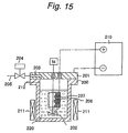
- the autoclave consists of a container body 200 made from SUS304 and a cover 201, and has an inner volume of 300 ml.
- An exhaust port 203 is formed in cover 201 and connected to an exhaust pipe 205 having a valve 204.
- the container also has a gas inlet 212 for introducing a purge gas.
- a cylindrical platinum plate electrode 206 (outer diameter 26.5 mm, height 60 mm, effective area 50 cm 2 , initial dry weight 35.525 g) was provided in the autoclave. Although electrode 206 is shown as a net member, it was not a net but a plate in this example. Electrode 206 was connected to the positive electrode of outer power source 210, while cover 201 was connected to the negative electrode of the outer power source so that the inner wall face of the container body served as a cathode.
- An artificial waste liquor consisting of 4,000 mg/L acetic acid (TOC 1,600 mg/L), 2 wt% NaCl and tap water was prepared.
- Spherical particles of silicon dioxide (glass beads) were coated with copper by electroless plating to prepare conductive particles. These conductive particles contain 5 wt% copper on the basis of the total weight of said conductive particles. These conductive particles had an average particle diameter of 0.2 mm.
- To 150 mL of said artificial waste liquor was added 5 g of said conductive particles.
- the artificial waste liquor was treated under the same conditions as in the example above except that no conductive particles were added to the artificial waste liquor.
- the average voltage was as low as 3.04 V.
- the effluent showed a TOC of 954 mg/L with TOC degradation of only 40.3%.
- Hydrothermal electrolytic processes and apparatus allow a large amount of waste liquor to be efficiently and continuously treated.
- Hydrothermal electrolytic apparatus of the present invention are well suitable for continuous processes, but also applicable to batch processes or semi-continuous processes.
Landscapes
- Chemical & Material Sciences (AREA)
- Chemical Kinetics & Catalysis (AREA)
- Engineering & Computer Science (AREA)
- Organic Chemistry (AREA)
- Environmental & Geological Engineering (AREA)
- General Chemical & Material Sciences (AREA)
- Life Sciences & Earth Sciences (AREA)
- Hydrology & Water Resources (AREA)
- Electrochemistry (AREA)
- Water Supply & Treatment (AREA)
- Analytical Chemistry (AREA)
- Oil, Petroleum & Natural Gas (AREA)
- Health & Medical Sciences (AREA)
- Biomedical Technology (AREA)
- Water Treatment By Electricity Or Magnetism (AREA)
- Treatment Of Water By Oxidation Or Reduction (AREA)
- Electrolytic Production Of Non-Metals, Compounds, Apparatuses Therefor (AREA)
Abstract
An object of the present invention is to provide a
hydrothermal electrolytic apparatus that allows a large
amount of waste liquor to be efficiently treated. In order
to attain this object, a hydrothermal electrolytic
apparatus according to an aspect of the present invention
comprises a reaction cell for electrolyzing influent at
high temperature and high pressure wherein the overall
surface area of a pair of electrodes located in the
reaction cell 31 per 1 m3 of the volume of the influent is
0.05 m2 or more. A hydrothermal electrolytic apparatus
according to one embodiment of the present invention has
two or more tubular reaction cells each having a metal
inner wall serving as a cathode and an anode is provided in
each of said reaction cells. A hydrothermal electrolytic
process according to another aspect of the present
invention comprises incorporating conductive particles into
the influent to substantially increase the surface area of
electrodes in hydrothermal electrolysis.
Description
The present invention relates to apparatus and
processes for performing hydrothermal reaction and
electrolysis at the same time. As used herein,
hydrothermal electrolysis means that hydrothermal reaction
and electrolysis are performed at the same time. According
to the present invention, a large amount of influent
containing reducible substances such as organics (including
synthetic polymers) and ammonia, eg, organic waste liquors
or various industrial waste liquors containing a halide ion
can be continuously treated.
International Application PCT/JP 98/03544 filed
August 10, 1998 (International Publication WO99/07641)
discloses hydrothermal electrolytic processes and apparatus
previously developed by us. According to these processes
and apparatus, reducible substances such as organics
(including synthetic polymers) or ammonia can be effectively
oxidatively degraded by performing hydrothermal
reaction and electrolysis at the same time. When an
oxidizer or a strong acid ion such as a halide ion is
contained in the influent, hydrogen emission can be
inhibited in hydrothermal electrolysis. The disclosure of
International Application PCT/JP 98/03544 is incorporated
herein as a whole as reference.
In hydrothermal electrolysis, a closed pressure-resistant
vessel is typically used as a reaction vessel
because a high pressure environment is required. Thus, a
batch process or a semi-continuous or continuous process
consisting of repeated batch processes is applied when
waste liquor is to be clarified by hydrothermal
electrolysis.
However, only a small amount of waste liquor could be
treated at a time and it was difficult to treat a large
amount of waste liquor by a batch process or a semi-continuous
process. For example, it is necessary to supply
waste liquor and replace treated effluent each time in the
case of a batch process. However, the operation for
bolting a flange or the like requires labor and care in
order to perform a reaction at high temperature and high
pressure. These processes are inefficient in terms of
operating time or running costs.
When waste liquor is to be continuously treated, a
large amount of electric power must be supplied in
proportion to the amount of waste liquor. Especially when
a large amount of high-load influent is to be continuously
treated, a quite large amount of electric power must be
supplied, which may sometimes correspond to several
thousands to several tens of thousands of amperes of dc.
However, it is sometimes difficult to apply several
hundreds to several thousands of amperes of dc, considering
that the permissive current density has a limitation
depending on the electrode material. As the reaction
vessel becomes larger, it also becomes more difficult to
homogeneously supply electric power on the electrode
surface to homogeneously advance the reaction.
Therefore, an object of the present invention is to
provide a hydrothermal electrolytic apparatus capable of
efficiency and continuously treating a large amount of
waste liquor.
As a result of examinations to solve the above
problems, we found that a large amount of waste liquor can
be efficiently treated by increasing the surface area of
electrodes in a high-pressure vessel.
An aspect of the present invention provides a
hydrothermal electrolytic apparatus comprising a reaction
cell for electrolyzing an influent containing water and
reducible substances at high temperature and high pressure,
wherein said reaction cell defines a chamber and has a pair
of electrodes and the overall surface area of said pair of
electrodes exposed in said chamber per 1 m3 of the volume
of said chamber in said reaction cell is 0.05 m2 or more.
Preferably, the hydrothermal electrolytic apparatus
of the present invention has an inlet at the bottom of the
reaction cell for introducing an influent and an outlet at
the top for discharging an effluent. This facilitates
continuous treatment of influents.
Preferably, said reaction cell comprises two or more
tubular reaction cells each having a metal inner wall
serving as a cathode, and an anode is provided in each of
said reaction cell. The anode and the cathode can form
said pair of electrodes.
Alternatively, said pair of electrodes preferably
have a first electrode having two or more concentrically
cylindrical first side walls and a first connecting member
for connecting said first side walls together, and a second
electrode having two or more concentrically cylindrical
second side walls and a second connecting member for
connecting said second side walls together, wherein said
first side walls of said first electrode and said second
side walls of said second electrode are alternately
arranged to form a channel for influent between said first
side walls and said second side walls.
Moreover, the hydrothermal electrolytic apparatus of
the present invention preferably further has a high-pressure
pump, an influent line for supplying influent to
said reaction cell, an oxidizer line for supplying an
oxidizer to said reaction cell, and an effluent line for
discharging effluent from said reaction cell.
Another aspect of the present invention provides a
process for preparing clarified water, comprising the steps
of introducing an influent containing water and reducible
substances into a reaction cell of said hydrothermal
electrolytic apparatus, supplying a direct current into
said reaction cell at a temperature of 100°C or more but
the critical temperature of said influent or less and at a
pressure that allows water in said influent to be kept in
the liquid phase, and discharging an effluent from said
reaction cell. This clarified water may be recycled to
another process or discharged to the environment.
Preferred embodiments of the present invention are
explained in detail below with reference to the attached
drawings.
Fig. 1 is a longitudinal sectional view showing the
inner structure of reaction vessel 1 forming the core of
the hydrothermal electrolytic apparatus according to a
first embodiment of the present invention, Fig. 2 is a
widthwise sectional view showing the inner structure of the
reaction vessel. Fig. 3 is an enlarged sectional view of B
in Fig. 1. Fig. 4 is an enlarged sectional view of C in
Fig. 2. Fig. 4 shows a section of the part at which a
spacer 43 is provided.
As shown in Figs. 1-4, the hydrothermal electrolytic
apparatus according to this embodiment comprises a reaction
cell 31 for electrolyzing an influent containing water at
high temperature and high pressure. Reaction cell 31
defines chambers 7 and has a pair of electrodes 31a, 41.
Thus, the inner face of reaction cell 31 can serve as
electrode 31a. The overall surface area of a pair of
electrodes 31a, 41 exposed in chamber 7 in reaction cell 31
per 1 m3 of the volume of the chamber is 0.05 m2 or more,
preferably 0.1 m2 or more, more preferably 0.2 m2 or more.
The "overall surface area of electrodes" here means the
effective surface area of electrodes substantially
participating in electrolytic reaction.
If the overall surface area of a pair of electrodes
31a, 41 is less than 0.05 m2, enough electric power can not
be supplied to the influent for rapid hydrothermal
electrolysis.
In the first embodiment of the present invention
shown in Fig. 1, the reaction cell consists of two or more
tubular reaction cells 31. Each of reaction cells 31 has a
metal inner wall 31a serving as a cathode and a discharge
electrode 41 serving as an anode is provided in each of
said reaction cells 31.
The first embodiment of the present invention
comprises a reaction vessel 1. Reaction vessel 1 comprises
a lower vessel part 2, a middle vessel part 3 and an upper
vessel part 4. Lower vessel part 2 comprises an inlet 21
for introducing influent, an oxidizer inlet 22 for
introducing an oxidizer, and a mixing chamber 23 for mixing
the influent introduced from inlet 21 with the oxidizer
introduced from oxidizer inlet 22. Middle vessel part 3
comprises reaction cells 31 in which the influent mixed
with an oxidizer is electrolyzed under pressure and heating.
Each of inlet 21 and oxidizer inlet 22 is singly
provided in a wall portion 2a on the bottom of lower vessel
part 2. Inlet 21 is connected to an influent line and
oxidizer inlet 22 is connected to an oxidizer line.
Mixing chamber 23 is partitioned by a dispersion
plate 24 and contains a stirrer 25 therein. Dispersion
plate 24 may be any known means for mixing the influent by
disturbing the flow. Stirrer 25 is a common type having
stirring blades 25a and used to help mixing and connected
to a motor not shown.
At the connection between lower vessel part 2 and
middle vessel part 3 is provided an introducing chamber 6
for smoothly introducing the influent mixed with an
oxidizer in mixing chamber 23 into reaction cell 31. Wall
3a of middle vessel part 3 is connected to a negative line
32, which is in turn connected to a negative terminal not
shown of a do source at constant current and voltage.
The tubular body forming reaction cell 31 is
electrically connected with wall 3a of middle vessel part 3.
For example, a stainless steel tube may be welded to a
stainless steel middle vessel part 3. Thus, the entire
inner face 31a of reaction cell 31 serves as a cathode.
Reaction cell 31 may be integrally formed with middle
vessel part 3 or separately formed and fitted or otherwise
incorporated into it. Thus, the inner face 31a of reaction
cell 31 serves as a negative electrode to prevent corrosion
by electrolysis.
In the present invention, the distance between the
anode and the cathode is preferably equal. If this
distance varies, an excessive current flows locally at
narrow regions to accelerate deterioration of the anode at
those regions. In this embodiment, inner wall 31a of
reaction cell 31 preferably has a cylindrical shape.
Preferably, the outer peripheral face of discharge
electrode 41 also has a cylindrical shape so that the
center axis of discharge electrode 41 substantially
coincides with the center axis of inner wall 31a of
reaction cell 31.
At an end of discharge electrode 41 is provided an
insulating spacer 43 to prevent any contact with the inner
face of reaction cell 31. Insulating spacer 43 is
preferably formed to suit the shape of the outer surface of
discharge electrode 41 and the shape of the inner face of
reaction cell 31. Insulating spacer 43 preferably has a
through hole that allows the influent to pass.
A chamber 7 is formed between the inner face of
reaction cell 31 and discharge electrode 41 and connected
to a discharge channel 8 formed at the connection between
middle vessel part 3 and upper vessel part 4. Discharge
channel 8 is connected to an outlet 34 at the upper end of
middle vessel part 4 for discharging effluent from reaction
vessel 1.
Thus, the reaction vessel in the hydrothermal
electrolytic apparatus according to this embodiment has an
inlet at the bottom for introducing an influent and an
outlet at the top for discharging an effluent. This makes
it easier to continuously hydrothermally electrolyze an
influent. The reaction vessel has a plurality of rod-like
discharge electrodes and the same number of reaction cells.
As used herein, the "volume of the chamber in the
reaction cell" does not include the volume of discharge
electrode 41 in reaction cell 31 but means the volume of
the part where an influent is electrolyzed at high
temperature and high pressure. In this embodiment, it
specifically means the volume of chamber 7 located between
electrodes 31a, 41 in reaction cell 31.
In this embodiment, the "overall surface area of a
pair of electrodes exposed in the chamber" means the total
of the surface area of electrode 31a and the surface area
of discharge electrode 41 exposed in chamber 7. This
excludes the area of discharge electrode 41 not exposed in
chamber 7, eg, the surface area of the part of the
discharge electrode located within upper vessel part 4 or
the surface area of the part of the discharge electrode
exposed in discharge channel 8 because these parts do not
participate in the electrolysis of an influent.
Each member can be formed from any material so far as
middle vessel part 3 and reaction cell 31 should be formed
from an electrically conductive material and the reaction
vessel as a whole should be formed from a heat-resistant
and pressure-resistant material. For example, middle
vessel part 3 and reaction cell 31 can be formed from
stainless steel. Reaction cell 31 may have a multilayer
structure comprising the innermost layer of an electrically
conductive material such as stainless steel and the other
layers of ceramics.
The hydrothermal electrolytic apparatus according to
this embodiment can be used as follows.
An influent is heated up to a subcritical temperature
and then introduced via inlet 21. At the same time, an
oxidizer such as oxygen-dissolved water is introduced via
oxidizer inlet 22 and mixed with the influent in mixing
chamber 23. The influent mixed with the oxidizer is forced
upward under the pressure of successively introduced
influent and oxidizer and inserted into reaction cell 31
via lower opening 31b of reaction cell 31. The influent
introduced into reaction cell 31 is subjected to
hydrothermal reaction and electrolytic oxidation reaction
as it moves in chamber 7 so that reducible substances in
the influent are degraded. The treated influent is
introduced into discharge channel 8 via upper opening 31c
and discharged from outlet 34. The effluent after
treatment is introduced into various tanks as in known
processes. In the apparatus according to this embodiment,
a series of these reaction processes can be continuously
performed.
The hydrothermal electrolytic apparatus according to
this embodiment has the advantage that a large amount of
influent can be treated because the reaction vessel has
electrodes of a specific area as described above, which
increases the throughput and advances a homogeneous
reaction. Moreover, this embodiment allows a large amount
of influent to be continuously treated even using a
reaction vessel having an inlet at the bottom and an outlet
at the top because said electrodes have a specific area.
This embodiment also has the advantage that current feed
terminals are easily mounted to improve workability.
Therefore, the apparatus of the present invention
improves the efficiency of hydrothermal electrolytic
reaction to effectively use the input energy and also
reduces the size of the apparatus by increasing the surface
area of electrodes per volume of chambers.
Next, a second embodiment of the present invention is
explained with reference to Figs. 5-9, in which Fig. 5 is a
longitudinal sectional view showing the inner structure of
the reaction vessel forming the core of the hydrothermal
electrolytic apparatus according to a second embodiment of
the present invention, Fig. 6 is a widthwise sectional view
showing the inner structure of the reaction vessel, Fig. 7
is an enlarged sectional view of E in Fig. 5, Fig. 8 is an
enlarged sectional view of F in Fig. 6, and Fig. 9 is an
enlarged sectional view of G in Fig. 5. In the following
description, differences from the first embodiment are
described especially in detail. The foregoing explanation
about the first embodiment is appropriately applied when no
special reference is made.
In the second embodiment shown in Figs. 5-9, lower
vessel part 2 has an influent inlet 21 at the center of the
bottom, and a pipe 26 is connected to inlet 21 to extend
upward from lower vessel part 2 to middle vessel part 3.
Influent has been preliminarily mixed with an oxidizer in a
mixer not shown, if desired. Preferably, influent has been
preliminarily heated up to a temperature of 100°C or more
but the critical temperature or less.
Preferably, pipe 26 is electrically connected to
connecting member 36b to serve as cathode 35b. Thus, pipe
26 and the reaction vessel body can be protected against
corrosion by cathodic protection.
Both connecting members 36a, 36b are in the form of a
disk and electrically conductive. Connecting member 36a
fixes anode 35a to current feed terminals 42. Connecting
member 36b fixes cathode 35b to lower vessel part 2.
Thus, the hydrothermal electrolytic reactor according
to this embodiment has a concentrically cylindrical
continuous reaction channel. The reaction channel is
continuously provided from the center to the outer
periphery of the reaction vessel so that influent flows
from the center to the outer periphery of the reaction
vessel. Upper vessel part 4 includes a plurality of
current feed terminals 42. Upper vessel part 4 and current
feed terminals 42 are electrically insulated from each
other via an insulator 42a, as shown in Fig. 9.
In this embodiment, the "volume of chambers in the
reaction cell" means the volume of the part where the
influent is hydrothermally electrolyzed in middle vessel
part 3. The "volume of chambers in the reaction cell"
excludes the volume of anode 35a, the volume of cathode 35b
and the volume defined by pipe 26.
When pipe 26 serves as a cathode, radially outer
channels of pipe 26 are included in the chamber. When pipe
26 is not electrically conductive and does not serve as an
electrode, however, radially outer channels of pipe 26 are
not included in the chamber.
In the apparatus according to this embodiment,
influent is introduced from inlet 21 and transferred to the
top of the reaction vessel through pipe 26, then
transferred from the top to the bottom of the reaction
vessel in the outer channel, then transferred from the
bottom to the top in the subsequent outer channel, and so
on. Thus, it is transferred successively from the center
to the periphery of the reaction vessel. During then,
reducible substances in the influent are oxidatively
degraded by hydrothermal electrolysis. The treated
influent is discharged from outlet 34 to the outside of
reaction vessel 1.
In addition to the same advantages as obtained in the
first embodiment, the apparatus according to this
embodiment also has the advantage that the reaction channel
can be longer to improve the efficiency of electrolysis.
Thus, even low-concentration influents can be effectively
treated.
Hydrothermal electrolytic apparatus according to the
first and second embodiments are not limited to the
foregoing embodiments, but can be modified in various
respects without departing from the spirit of the present
invention.
For example, a mixing chamber having a stirrer was
illustrated in the first embodiment, but the mixing chamber
may not be necessary as shown in the second embodiment.
The mixing chamber may not necessarily have a stirrer or a
dispersion plate so far as the influent and oxidizer or the
like are mixed.
The embodiment shown in Figs. 2 and 3 may be replaced
by the embodiment shown in Figs. 10 and 11. That is, a
heat-insulating material 39 may be filled outside reaction
cell 31 in middle vessel part 3.
Alternatively, the reaction vessel may be thermally
insulated by evacuation from a vacuum pump via a port
formed in middle vessel part 3 instead of using an
insulating material.
Alternatively, the temperature may be kept by
providing a heater 45 on the outer peripheral face of
middle vessel part 3 as shown in Fig. 12. Ports 46 and 47
may be further provided in middle vessel part 3 as shown in
Fig. 12. Thus, the temperature can be kept constant by
directly heating the inside of middle vessel part 3 with a
thermal fluid flown from port 46 into middle vessel part 3.
The thermal fluid is discharged from port 47. The thermal
fluid may be used not only for heating but also cooling.
It is useful to provide a heater on the outer
peripheral face of middle vessel part 3 as shown in Fig. 12
especially in the second embodiment in which the
temperature of the influent may be lowered as it closes to
the peripheral face of the vessel.
Next, materials of members, reaction conditions or
the like that can be used in the present invention are
described. In hydrothermal electrolytic apparatus of the
present invention, the discharge electrode or anode
preferably has a surface having ruthenium, iridium,
platinum, palladium, rhodium, tin or an oxide thereof or a
ferrite. For example, the discharge electrode itself may
be made from these materials. Alternatively, the base
material of the discharge electrode may be coated with
these materials on the surface.
Ruthenium, iridium, platinum, palladium, rhodium and
tin may be elemental metals or oxides. Alloys of these
metals are also preferably used. Such alloys include, for
example, platinum-iridium, ruthenium-tin and ruthenium-titanium.
These metals show high corrosion resistance,
excellent insolubility for use as an anode. In some
embodiments, especially preferred electrodes are based on
palladium, ruthenium or an alloy of platinum and iridium.
During the hydrothermal electrolytic reaction of the
present invention, the current density at the surface of
the anode is preferably 0.1 mA/dm2 - 500 A/dm2. If the
current density is higher than 500 A/dm2, the surface of
the anode is liable to be exfoliated or dissolved. If the
current density is lower than 0.1 mA/dm2, however, the area
of the anode must be increased and the system becomes bulky.
The current density is more preferably 10 mA/dm2 - 100 A/dm2,
most preferably 100 mA/dm2 - 50 A/dm2. If a new material
for the anode is developed, the current density at the
anode can be further increased.
In hydrothermal electrolytic apparatus and processes
of the present invention, an influent containing water and
reducible substances can be treated to oxidatively degrade
the reducible substances. Influents that can be treated by
the present invention include various waste liquors.
Reducible substances that can be degraded by the present
invention include organics and ammonia. Examples of
organics include aliphatic and aromatic hydrocarbons such
as alkanes, alkenes, alkynes; alcohols; aldehydes; ketones;
amines; carboxylic acids such as acetic acid; carboxylic
acid derivatives such as esters, amides, anhydrides;
halogenated hydrocarbons; phenols; sulfur-containing
organic compounds such as sulfoxides, mercaptans, thiols,
polysulfones; etc. Organics also include synthetic
polymers such as polyolefins, polyesters or various
engineering plastics.
Influents preferably have fluidity, and may be any of
suspension, emulsion, aqueous solution or slurry, but
preferably suspension or slurry. Influents may contain
liquid or solid reducible substances. Influents include
suspensions of unprecipitable solid particles dispersed in
water, emulsions of liquid particles dispersed in water,
aqueous solutions of liquid organics or inorganics
dissolved in water and mixtures thereof. For example,
influents contain a continuous phase containing water,
liquid organics and dissolved salts and a discontinuous
phase containing solid organics such as particles, and
optionally non-combustible solids such as ash.
Preferably, influents contain a strong acid ion.
This is because strong acid ions show an electrochemical
catalytic effect to advance hydrothermal electrolytic
reaction more efficiently. The strong acid ion may be an
inorganic acid ion or an organic acid ion. However, the
strong acid is preferably an inorganic acid ion because
organic acid ions may be degraded as hydrothermal
electrolysis proceeds.
Suitable inorganic strong acid ions include, for
example, halide ions, sulfate ion (SO4 2-), nitrate ion (NO3 -),
phosphate ion (PO4 3-), among which halide ions are
especially preferred. Suitable organic strong acid ions
include, for example, trifluoroacetate ion (CF3COO-).
Suitable halide ions include chloride ion (Cl-),
bromide ion (Br-), iodide ion (I-) or any combination
thereof, among which chloride ion or bromide ion is
especially preferred. A halide ion-producing salt may be
dissolved in the influent. A hydrohalic acid such as
hydrogen chloride (HCl), hydrogen bromide (HBr) or hydrogen
iodide (HI) may be contained in the influent. When the
influent contains polyvinyl chloride, chloride ion moves to
the aqueous phase to incorporate chloride ion as
hydrothermal reaction proceeds.
In hydrothermal electrolysis according to the present
invention, an oxidizer is preferably added to the influent
to more efficiently advance hydrothermal electrolytic
oxidation. Oxidizers that can be used in the present
invention are oxygen gas, ozone gas, hydrogen peroxide and
hypohalous acids, more preferably oxygen gas. Oxygen gas
may be a gas containing oxygen gas, eg, air is preferably
used. Thus, air can be bubbled into water or the like to
dissolve oxygen, and the resulting oxygen-dissolved water
can be introduced as an oxidizer via oxidizer inlet 22.
Alternatively, compressed air can be introduced into
reaction cell 23 to serve as an oxidizer.
In hydrothermal electrolysis according to the present
invention, hydrothermal reaction takes place at a
temperature of 100°C or more but the critical temperature
of said influent or less and at a pressure that allows said
influent to be kept in the liquid phase. Temperatures
lower than 100°C are not preferred because the rate of
hydrothermal reaction is lowered to extend the reaction
time. However, the finding of the present invention cannot
be directly applied for temperatures higher than the
critical temperature because physical properties of aqueous
medium significantly change. At the supercritical stage,
for example, the solubility of the electrolyte greatly
decreases and electric conductivity is decreased.
Next, a specific arrangement of an influent treatment
system using a hydrothermal electrolytic reactor according
to the present invention is explained with reference to Fig.
13. Fig. 13 shows such an influent treatment system. In
the treatment system shown in Fig. 13, an influent line 60
for supplying an influent is connected to a hydrothermal
electrolytic reaction vessel 1 of the present invention.
Influent line 60 preferably has a feed tank 61, a high-pressure
pump 66, a heat exchanger 70 and a heater 74, and
an influent can be transferred in this order. Hydrothermal
electrolytic reaction vessel 1 may consist of a
hydrothermal electrolytic reaction vessel according to the
first embodiment, a hydrothermal electrolytic reaction
vessel according to the second embodiment or the like.
High-pressure pump 66 pressurizes the influent to a
pressure required for hydrothermal reaction to force the
influent into reaction vessel 1 under this pressure via
heat exchanger 70 and heater 74.
Preferably, influent line 60 has a heater 74 for
further heating the influent heated by heat exchanger 70.
Especially when reaction vessel 1 has a large diameter, it
is inefficient to heat influent 52 in reaction vessel 1
from the outside of reaction vessel 1 and it is thus
preferable to provide heater 74 in the influent line.
Heater 74 heats the influent to a temperature required for
hydrothermal reaction, for example. The temperature to
which the influent is heated is determined taking into
account the exothermic heat from the oxidation reaction and
the exothermic heat from the electrolysis of reducible
substances in reaction vessel 1. Another heater for
heating the outside of reaction vessel 1 may be further
provided.
Separately from influent line 60, an oxidizer line 80
is preferably provided. Suitable oxidizers include gases
containing oxygen gas such as air. Air is introduced into
compressor 82 via line 81 and preferably pressurized from
1 MPa to 25 MPa, for example. This compressed air is
introduced into accumulator 84 via line 83. Thus,
compressor-induced pulsation of compressed air can be
prevented.
A valve 85 for controlling the amount of compressed
air, ie, the amount of oxidizer is provided downstream of
accumulator 84. Compressed air is preheated in heat
exchanger 87 and then introduced into reaction vessel 150
via line 188. Heat exchanger 187 heats compressed air and
cools the effluent.
Alternatively, a liquid such as water in which oxygen
gas is dissolved may be introduced into reaction vessel 1.
Oxidizers in the form of a gas such as oxygen gas
(including air) have higher water-solubility at lower
temperature or higher pressure. Therefore, an oxidizer in
the form of a gas may be dissolved in water at low or room
temperature under high pressure and then this cold water
may be supplied to the reaction vessel. Alternatively,
aqueous hydrogen peroxide, a hypochlorous acid or a solid
oxidizer may be dissolved in water and supplied to the
reaction vessel via a high-pressure pump or the like. When
an oxidizer rich in water is added, an additional heater
may be provided between high-pressure pump 86 and reaction
vessel 1.
Preferably, oxidizer line 80 is directly connected to
reaction vessel 1. If oxidizer line 80 is connected to
influent line 60, line 76 between heater 74 and reaction
vessel 50 will be susceptible to corrosion. On the another
hand, when an oxidizer is directly introduced into reaction
vessel 1, the inner wall of reaction vessel 1 can be
protected from corrosion because the inner wall of reaction
vessel 11 serves as a cathode of electrolysis.
In the embodiment shown in Fig. 13, an effluent line
100 for discharging the hydrothermally electrolyzed
influent is connected to reaction vessel 1. Preferably,
effluent line 100 has heat exchangers 70/87, a gas-liquid
separator 102, and an effluent tank 110, and the effluent
hydrothermally electrolyzed in reaction vessel 1 can be
transferred in this order. Heat exchangers 70/87 have
already been explained.
Preferably, gas-liquid separator 102 is connected to
effluent line 100. Gas-liquid separator 102 separates gas
and liquid in the effluent. The effluent is held at a
predetermined level 104 in gas-liquid separator 102.
Pressure transmitter tube may be provided between the space
above said level 104 and the effluent below said level 104,
and a level detector, for determining the gas-liquid
interface or slurry level, may be provided in this pressure
transmitter tube. Level-detecting mechanism 106 may be
designed to measure the level 104 by the pressure
difference between gas and liquid to discharge the effluent
in such a manner that said level 104 may be fixed or within
a fixed range. Gas-liquid separator 102 may be provided
with a piezoelectric element for converting pressure into
an electric signal each above and below said level 104,
whereby this electric signal is entered into a level
detector to detect the pressure difference.
Preferably gas-liquid separator 102 has a level-controlling
mechanism 106 stabilizing the level of the
effluent in gas-liquid separator 102 within a fixed range.
Said level-controlling mechanism may have a level detector
for detecting the pressure difference between gas and the
effluent, a valve for discharging the effluent and a
controller for controlling the valve by a signal from the
level detector. The level-controlling mechanism may have a
pressure transmitter tube or a piezoelectric element.
A valve 108 is connected to gas-liquid separator 102
so that the effluent in gas-liquid separator 102 can be
discharged into container 110 when valve 108 is opened.
Preferably, switching of valve 108 is controlled by a
signal from level-controlling mechanism 106.
Gas-liquid separator 102 may have a pressure
controlling mechanism for controlling the pressure in the
gas-liquid separator within a predetermined range. Said
pressure controlling mechanism may have, for example, a
pressure detector for detecting the pressure of the gas
phase, a valve for discharging gas and a controller for
controlling the valve by a signal from the pressure
detector. The pressure-controlling mechanism controls the
pressure in the range that the influent is kept at the
liquid phase and reaction vessel 1 and gas-liquid separator
102 are safely operated, for example. The pressure
detector may have a piezoelectric element.
A valve 109 is connected to gas-liquid separator 102
so that the gas in gas-liquid separator 102 can be
discharged to the atmosphere when valve 109 is opened.
Preferably, switching of valve 109 is controlled by a
signal from a pressure-controlling mechanism not shown.
Next, a hydrothermal electrolytic process using the
hydrothermal electrolytic treatment system shown in Fig. 13
is explained.
Explanation begins with the operation at start-up.
Suppose that no liquid has been introduced into reaction
vessel 1 yet. Tap water is first introduced into influent
line 60 from tap water line 68 at room temperature and
atmospheric pressure. Tap water is transferred through
heat exchanger 70, heater 74 and then reaction vessel 1 by
high-pressure pump 66. After tap water is introduced into
heater 74, heater 74 is activated to heat tap water. Thus
heated tap water is discharged from reaction vessel 1 to
effluent line 100 and then discharged into container 110
via gas-liquid separator 102.
After the system is stabilized, tap water supply from
the tap water line to influent line 60 is stopped and
influent supply from feed tank 61 to influent line 60 is
started. Halide ion level or other like of the influent
are preliminarily controlled via halide line 63 or the like,
The influent is introduced into reaction vessel 1 while
heating of the influent is continued in heater 74. An
oxidizer is introduced into reaction vessel 1 via oxidizer
line 80.
After the influent and oxidizer are introduced into
reaction vessel 1, electrolysis is started. Thus, dc
source 94 is turned on to supply dc to the anode and
cathode of hydrothermal electrolytic apparatus 1. The
influent kept in the liquid phase under high temperature
and high pressure moves in reaction vessel 1, during which
hydrothermal reaction and electrolysis proceed at the same
time. The heating temperature of heater 74 is
appropriately lowered because heat is generated with
hydrothermal reaction and electrolysis.
The reaction time should be enough long for reducible
substances in the influent to be oxidatively degraded, for
example 1 second to 48 hours, preferably 1 minute to 24
hours. The reaction time is more preferably 5 hours or
less, still more preferably 2 hours or less. The reaction
time is adjusted in function of the volume of reaction
vessel 1 and the feed flow rate of the influent.
When the reaction is to be stopped, the inflow from
feed tank 61 to influent line 60 is stopped and tap water
is introduced from the tap water line to influent line 60.
Oxidizer supply from oxidizer line 80 into reaction vessel
1 is also stopped. Then, the do source is turned off to
stop electrolysis. Then, the output of heater 74 is
lowered so that the temperature of the influent flowing
into reaction vessel 1 is gradually lowered.
According to the first and second embodiments of the
present invention, influent can be efficiently treated by
hydrothermal electrolytic reaction by increasing the
surface area of electrodes in hydrothermal electrolysis, as
has been described above.
However, it is not always easy to increase the
surface area of electrodes as desired because the surface
area of electrodes cannot be indefinitely increased in a
limited space of the reaction vessel even by the above
approach.
Thus, we also provide a process and an apparatus for
substantially increasing the surface area of electrodes
easily and inexpensively as alternatives to the foregoing
embodiments.
Namely, we found that the surface area of electrodes
can be substantially increased by incorporating
electrically conductive particles into the influent,
preferably suspending electrically conductive particles
into the influent so that the conductive particles present
in the influent can substantially serve as an electrode
during the electrolysis of the influent.
The incorporation of electrically conductive
particles into the influent means that the influent
containing water and electrically conductive particles is
located between the original cathode and the original anode
in the hydrothermal electrolytic apparatus. When a dc
voltage is applied across the original cathode and the
original anode, individual conductive particles serve as an
anode at the surfaces facing the original cathode and as a
cathode at the surfaces facing the original anode under the
effect of an electric field. Therefore, a current flows
locally between the original cathode and the surfaces of
individual conductive particles serving as an anode, and
also a current flows locally between the original anode and
the surfaces of conductive particles serving as a cathode.
When two conductive particles are located in proximity to
but without contact with each other and the cathodic
surface of one conductive particle faces the anodic surface
of the other conductive particle, for example, a current
flows locally between the cathodic surface and the anodic
surface. This also applies to more than two discrete
conductive particles, in which case a current seems to flow
between the cathodic surface of a conductive particle and
the anodic surface of another conductive particle.
Thus, the current flowing between the original anode
and the original cathode increases and the voltage across
the original anode and the original cathode also increases
when conductive particles exist in the influent as compared
with when no conductive particles exist in the influent.
Therefore, a large amount of electric power can be supplied
to the influent to greatly improve the throughput and
process efficiency of the hydrothermal electrolytic
apparatus without increasing the surface area of the
original anode and the original cathode.
Accordingly, a third aspect of the present invention
provides a hydrothermal electrolytic process comprising the
step of subjecting an influent containing water, reducible
substances and conductive particles to electrolysis at a
temperature of 100°C or more but the critical temperature
of said influent or less and at a pressure that allows
water in said influent to be kept in the liquid phase.
In the third aspect of the present invention, said
conductive particles are suspended in said influent, and
said influent preferably further contains a strong acid ion.
Preferably, said electrolysis step is followed by the step
of separating said conductive particles and the step of
adding the separated conductive particles to said influent
again.
Still another aspect of the present invention
provides a hydrothermal electrolytic apparatus comprising a
feeder for supplying an influent containing water and
reducible substances with conductive particles, and a
reaction cell for subjecting said influent supplied with
conductive particles to electrolysis at a temperature of
100°C or more but the critical temperature of said influent
or less and at a pressure that allows water in said
influent to be kept in the liquid phase. In said apparatus,
said reaction cell preferably has a pair of electrodes,
more preferably one of which serves as an anode and the
other serves as a cathode.
Still another aspect of the present invention
provides a hydrothermal electrolytic apparatus comprising a
reaction cell for supplying a direct current to an influent
containing water, reducible substances and conductive
particles at a temperature of 100°C or more but the
critical temperature of said influent or less and at a
pressure that allows water in said influent to be kept in
the liquid phase, and a separator for separating the
conductive particles from the effluent. Preferably, said
reaction cell has a pair of electrodes, more preferably one
of which serves as an anode and the other serves as a
cathode.
In said hydrothermal electrolytic apparatus, said
separator preferably comprises a liquid cyclone. Or said
separator preferably comprises a filter device.
In the third aspect of the present invention, the
influent contains conductive particles. When a do voltage
is applied across the original cathode and the original
anode in a hydrothermal electrolytic apparatus supplied
with a influent containing conductive particles, individual
conductive particles serve as an anode at the surfaces
facing the original cathode and as a cathode at the
surfaces facing the original anode under the effect of an
electric field. Therefore, a current flows locally between
the original cathode and the surfaces of individual
conductive particles serving as an anode, and also a
current flows locally between the original anode and the
surfaces of conductive particles serving as a cathode.
When two conductive particles are located in proximity to
but without contact with each other and the cathodic
surface of one conductive particle faces the anodic surface
of the other conductive particle, for example, a current
flows locally between the cathodic surface and the anodic
surface. This also applies to more than two discrete
conductive particles, in which case a current seems to flow
between the cathodic surface of a conductive particle and
the anodic surface of another conductive particle.
Therefore, the surface area of electrodes can be
substantially increased without increasing the surface area
of the original anode and the original cathode.
Preferably, conductive particles are suspended in the
influent. As a result, solid conductive particles can flow
with the influent. This also prevents conductive particles
from adhering to the surface of electrodes.
Conductive particles may be wholly formed of a
conductive material. Alternatively, they may be particles
of a conductive material coated with another conductive
material on their surfaces or particles of a non-conductive
material coated with a conductive material on their
surfaces. Even particles having an insulating oxide or the
like deposited on their surfaces by corrosion or other
reasons are regarded as conductive particles so far as they
are generally conductive.
Particles formed of a conductive material include,
for example, carbon particles, metal particles and
conductive oxide particles. Carbon particles include, for
example, particles of graphite. Metal particles include,
for example, so-called metal powders such as iron powder,
copper powder, silver powder, nickel powder, cobalt powder
and aluminium powder. Conductive oxide particles include
particles of a ferrite and ruthenium oxide. In terms of
costs, iron powder and aluminium powder are preferred.
Iron powder includes powdered scrap from machining of steel
(including stainless steel), cast iron or the like.
Particles of a conductive material coated with
another conductive material include metal particles coated
with a thin film of another metal on their surfaces such as
copper particles coated with platinum on their surfaces.
Particles of a non-conductive material coated with a
conductive material on their surfaces include particles of
an oxide powder coated with a metal thin film on their
surfaces such as aluminium oxide particles coated with
copper on their surfaces.
Particles of a conductive or non-conductive oxide
powder coated with a conductive oxide on their surfaces are
also suitable, such as zirconium oxide particles coated
with iridium oxide on their surfaces and silicon dioxide
particles coated with ruthenium oxide on their surfaces.
Synthetic polymer particles coated with a metal or a
conductive oxide on their surfaces are also suitable, such
as polymer particles of polyethylene glycol coated with
ruthenium oxide on their surfaces.
Means for coating a metal thin film include
electroplating, electroless plating, sputtering, physical
vapor deposition, chemical vapor deposition, etc. Means for
coating a conductive oxide thin film include calcination,
sputtering, physical vapor deposition, chemical vapor
deposition, etc.
These conductive particles are subjected to a current
in the presence of a strong acid ion such as a halide ion
at high temperature and high pressure. Suitable conductive
particles may be irreversible particles liable to be molten
or corroded under these conditions or reusable chemically
stable particles. For single use, iron powder, aluminium
powder or the like are preferred in terms of costs.
Reusable conductive particles preferably have such an
excellent corrosion resistance that they remain insoluble
even if a current is applied.
Reusable conductive particles are preferably formed
of or coated with a conductive material having ruthenium,
iridium, platinum, palladium, rhodium, copper, nickel, tin
or an oxide thereof or a ferrite.
Ruthenium, iridium, platinum, palladium, rhodium,
copper, nickel and tin may be elementary metals or oxides.
Alloys of these metals are also preferably used. Such
alloys include, for example, platinum-iridium, ruthenium-tin
and ruthenium-titanium. In some embodiments,
conductive materials based on palladium, ruthenium or an
alloy of platinum and iridium are especially preferred.
Conductive particles may be in any form such as, but
not limited to, sphere, rod, disk, T-shape, donut, tube,
fiber, etc. Hollow particles are also suitable.
Conductive particles preferably have a size shorter
than the distance between the anode and the cathode. The
average size of conductive particles is preferably 1 cm or
less, more preferably 5 mm or less, still more preferably
1 mm or less, most preferably 0.5 mm or less. For example,
the size of spherical conductive particles means their
diameter. The size of rod-like or tubular conductive
particles means their length. The size of conductive
particles may be homogeneous or may widely vary.
Rod-like or tubular conductive particles preferably
have an aspect ratio, ie, the ratio of the length to the
diameter of the rod or tube of 0.1-1000, more preferably
0.5-100.
The influent preferably contains 0.01% by weight or
more of conductive particles, more preferably 0.1% by
weight or more of conductive particles. The presence of
conductive particles in an amount even as small as 0.01% by
weight in the influent increases a current, therefore a
voltage across the original electrodes.
The influent preferably contains 30% by weight or
less of conductive particles, more preferably 10% by weight
or less of conductive particles. If more than 30% by
weight of conductive particles are contained, the fluidity
of the influent is affected and the probability of a short
circuit between electrodes significantly increases.
The content of conductive particles in the influent
means the content in the feed line for supplying the
influent into the reaction cell. This is because
conductive particles are not always uniformly distributed
in the reaction cell so that the content is difficult to
exactly determine. When the reaction cell is tubular and
the influent is transferred from the bottom to the top, for
example, the concentration of conductive particles tends to
be higher at the bottom of the reaction cell.
The third aspect of the present invention as defined
above is explained in detail below with reference to Fig.
14. In Fig. 14, elements having the same operation and
function as those of the treatment system shown in Fig. 13
are designated by the same reference numbers and not
explained here.
In a hydrothermal electrolytic treatment system
according to the third aspect of the present invention
shown in Fig. 14, influent line 60 for supplying an
influent is connected to reaction vessel 50. Influent line
60 preferably has a feed tank 61, a high-pressure pump 66,
a heat exchanger 70 and a heater 74, and an influent can be
transferred in this order.
A feeder 130 for supplying conductive particles to
feed tank 61 is provided. Feeder 130 comprises a hopper
132 for holding conductive particles 138 and a screw feeder
134 for quantitatively supplying conductive particles 138
to feed tank 61. A motor 136 is connected to screw feeder
134. The screw of screw feeder 134 rotates with the
rotation of motor 136 to introduce a metered amount of
conductive particles 138 into feed tank 61. Hopper 132 may
be supplied with crude conductive particles or conductive
particles 112 separated by filter device 114. Feed tank 61
is equipped with a stirrer 61a for homogeneously agitating
the influent.
Each member on influent line 60 has the same
operation as explained about Fig. 13, and is not explained
here.
Separately from influent line 60, an oxidizer line 80
is preferably provided. Each member on the oxidizer line
also has the same operation as explained about Fig. 13, and
is not explained here.
Preferably, reaction vessel 50 has an axially
extending tubular shape, preferably a cylindrical shape.
Reaction vessel 50 includes a pair of electrodes for
electrolysis therein. Reaction vessel 50 has a metal inner
wall 50s, which can serve as a cathode. For example, the
wall of reaction vessel 50 may be wholly made from a metal.
Reaction vessel 50 contains a rod-like anode 92 therein.
Preferably, the outer face of anode 92 is also cylindrical
so that the center axis of anode 92 substantially coincides
with the center axis of reaction vessel 50. Anode 92 may
be a cylindrically shaped mesh or net or a cylindrically
shaped plate.
In the treatment system shown in Fig. 14, a recycle
line 120 for recycling conductive particles is connected to
the reaction vessel. Recycle line 120 comprises a
separator 122 for separating conductive particles from the
effluent. Thus, conductive particles can be recycled
without being discharged from the system.
Thus, a separator 122 for separating solid particles
from the effluent is connected to the top of reaction
vessel 50 via line 121. Separator 122 may consist of, for
example, a liquid cyclone that centrifugally separates
conductive particles. In the liquid cyclone, conductive
particles settle at the bottom. In separator 122, all the
conductive particles in the effluent may not be separated.
Most of conductive particles may be removed in separator
122 and the remainder may be removed by filter device 110.
An effluent line 100 for discharging the effluent
deprived of at least a part of conductive particles is
connected to separator 122. Effluent line 100 preferably
has heat exchangers 87/70, a gas-liquid separator 102, and
a filter device 110, and the effluent hydrothermally
electrolyzed in reaction vessel 50 is transferred in this
order.
Preferably, gas-liquid separator 102 is connected to
effluent line 100. Gas-liquid separator 102 separates gas
and liquid in the effluent. The effluent is held at a
predetermined level 104 in gas-liquid separator 102. A
pressure transmitter tube may be provided between the space
above said level 104 and the effluent below said level 104,
and a level detector for determining the gas-liquid
interface or slurry level may be provided in this pressure
transmitter tube. A level detecting mechanism not shown
may be designed to measure the level 104 by the pressure
difference between gas and liquid to discharge the effluent
in such a manner that said level 104 may be fixed or within
a fixed range. Gas-liquid separator 102 may be provided
with a piezoelectric element for converting pressure into
an electric signal each above and below said level 104,
whereby this electric signal is entered into a level
detector to detect the pressure difference.
Preferably gas-liquid separator 102 has a level-controlling
mechanism 106 stabilizing the level of the
effluent in gas-liquid separator 102 within a fixed range.
Said level-controlling mechanism may have a level detector
for detecting the pressure difference between gas and the
effluent, a valve for discharging the effluent and a
controller for controlling the valve by a signal from the
level detector. The level-controlling mechanism may have a
pressure transmitter tube or a piezoelectric element.
A valve 108 is connected to gas-liquid separator 102
so that the treated water in gas-liquid separator 102 can
be discharged into filter device 114 when valve 108 is
opened. Preferably, switching of valve 108 is controlled
by a signal from the level-controlling mechanism.
Gas-liquid separator 102 may have a pressure
controlling mechanism for controlling the pressure in the
gas-liquid separator within a predetermined range. Said
pressure controlling mechanism may have, for example, a
pressure detector for detecting the pressure of the gas
phase, a valve for discharging gas and a controller for
controlling the valve by a signal from the pressure
detector. The pressure-controlling mechanism preferably
adjusts the pressure at a level that allows filter device
114 to accomplish smooth separation, for example. The
pressure detector may have a piezoelectric element.
A valve 109 is connected to gas-liquid separator 102
so that the gas in gas-liquid separator 102 can be
discharged to the atmosphere when valve 109 is opened.
Preferably, switching of valve 109 is controlled by a
signal from a pressure-controlling mechanism not shown.
In the embodiment shown in Fig. 14, the pressure of
gas-liquid separator 102 and the pressure of reaction
vessel 50 are preferably separately controlled so that the
pressure of reaction vessel 50 is adjusted at a pressure
that allows a liquid phase to be kept in hydrothermal
electrolysis and the pressure of gas-liquid separator 102
is adjusted at a pressure that allows dielectric particles
to be smoothly filtered by filter device 114.
For example, it is especially preferred that a
pressure-regulating valve 115 having a pressure sensor is
separately provided on line 100 to control the pressure of
reaction vessel 50. Thus, the pressure of reaction vessel
50 is kept on the inlet side of valve 115, so that the
pressure of reaction vessel 50 can be controlled via valve
115.
Next, a hydrothermal electrolytic process using the
hydrothermal electrolytic treatment system shown in Fig. 14
is explained.
The influent in feed tank 61 is transferred by high-pressure
pump 66, and the influent is preheated in heat
exchanger 70 and further heated in heater 74, and then
introduced into reaction vessel 50.
On the other hand, compressed air serving as an
oxidizer is supplied via oxidizer line 80 and preheated in
heat exchanger 87 and introduced into reaction vessel 50.
After the influent and oxidizer are introduced into
reaction vessel 1, electrolysis is started. Thus, do
source 94 is turned on to supply dc to anode 92 and
reaction vessel 50 serving as a cathode. The influent kept
in the liquid phase under high temperature and high
pressure moves from the bottom to the top in reaction
vessel 50, during which hydrothermal reaction and
electrolysis proceed at the same time to oxidatively
degrade reducible substances in the influent. In the
presence of a strong acid ion and conductive particles, do
can readily flow in the influent. The heating temperature
of heater 74 is appropriately lowered because heat is
generated with hydrothermal reaction and electrolysis.
The reaction time is enough long for reducible
substances in the influent to be oxidatively degraded, for
example 1 second to 48 hours, preferably 1 minute to 24
hours. The reaction time is more preferably 5 hours or
less, still more preferably 2 hours or less. The reaction
time is adjusted in function of the volume of reaction
vessel 50 and the feed flow rate of the influent.
The effluent discharged from separator 122 is
circulated through line 101, heat exchanger 87, line 102,
heat exchanger 70 and valve 108 and introduced into gas-liquid
separator 102.
Gas is discharged via valve 109, while liquid is
introduced into filter device 110 via valve 107. Filter
device 110 further removes conductive particles to
discharge the effluent into container 116.
In the embodiment of the present invention shown in
Fig. 14, a hydrothermal electrolytic apparatus according to
the first and second embodiments of the present invention
described with reference to Figs. 1-12 may be used as a
hydrothermal electrolytic reactor. If a hydrothermal
electrolytic apparatus having a plurality of reaction cells
as shown in Figs. 1-12 is used to hydrothermally
electrolyze an influent containing conductive particles,
the efficiency of electrolytic reaction in hydrothermal
electrolysis is further improved so that hydrothermal
electrolytic treatment can be performed more efficiently.
However, conductive particles contained in the influent
here should have a size smaller than the distance between
the anode and the cathode in each reaction cell.
The following examples illustrate a hydrothermal
electrolytic apparatus according to the third aspect of the
present invention without, however, limiting the present
invention thereto.
Experiments were made using an autoclave shown in
Fig. 15. The autoclave consists of a container body 200
made from SUS304 and a cover 201, and has an inner volume
of 300 ml. An exhaust port 203 is formed in cover 201 and
connected to an exhaust pipe 205 having a valve 204. The
container also has a gas inlet 212 for introducing a purge
gas.
A cylindrical platinum plate electrode 206 (outer
diameter 26.5 mm, height 60 mm, effective area 50 cm2,
initial dry weight 35.525 g) was provided in the autoclave.
Although electrode 206 is shown as a net member, it was not
a net but a plate in this example. Electrode 206 was
connected to the positive electrode of outer power source
210, while cover 201 was connected to the negative
electrode of the outer power source so that the inner wall
face of the container body served as a cathode.
An artificial waste liquor consisting of 4,000 mg/L
acetic acid (TOC 1,600 mg/L), 2 wt% NaCl and tap water was
prepared. Spherical particles of silicon dioxide (glass
beads) were coated with copper by electroless plating to
prepare conductive particles. These conductive particles
contain 5 wt% copper on the basis of the total weight of
said conductive particles. These conductive particles had
an average particle diameter of 0.2 mm. To 150 mL of said
artificial waste liquor was added 5 g of said conductive
particles.
At room temperature, 150 ml of said artificial waste
liquor containing 5 g of conductive particles was
introduced into the autoclave. Then, the autoclave was
filled with argon in an amount equivalent to 3 MPa and
sealed. Then, the content 220 was heated to 250°C by a
heater 211 under agitation with a stirring impeller 202.
When the temperature reached 250°C, application of a 6A
constant dc current across electrodes was started and
continued at 250°C for 15 minutes. During then, the
average voltage was 7.50 V. After a lapse of 15 minutes,
the application was stopped and the content was cooled to
room temperature. After said conductive particles in the
influent were settled, the supernatant was collected and
analyzed.
This supernatant was colorless and odorless, and had
a TOC of 30.4 mg/L. Thus, the TOC degradation reached
98.1%, showing tat the process of the present invention is
very effective.
In this comparative example, the artificial waste
liquor was treated under the same conditions as in the
example above except that no conductive particles were
added to the artificial waste liquor. When a 6A direct
current was applied across electrodes, the average voltage
was as low as 3.04 V. After treatment, the effluent showed
a TOC of 954 mg/L with TOC degradation of only 40.3%.
Thus, the current flowing in the influent increases
and the voltage across electrodes also increases when
conductive particles are suspended in the influent.
Hydrothermal electrolytic processes and apparatus
according to various aspects of the present invention allow
a large amount of waste liquor to be efficiently and
continuously treated. Hydrothermal electrolytic apparatus
of the present invention are well suitable for continuous
processes, but also applicable to batch processes or semi-continuous
processes.
Claims (15)
- A hydrothermal electrolytic apparatus comprising a reaction cell for electrolyzing an influent containing water and reducible substances at high temperature and high pressure, wherein said reaction cell defines a chamber and has a pair of electrodes and the overall surface area of said pair of electrodes exposed in said chamber per 1 m3 of the volume of said chamber in said reaction cell is 0.05 m2 or more.
- The hydrothermal electrolytic apparatus of Claim 1 having an inlet at the bottom for introducing influent and an outlet at the top for discharging effluent.
- The hydrothermal electrolytic apparatus of Claim 1 wherein said reaction cell comprises two or more tubular reaction cells each having a metal inner wall serving as a cathode and an anode is provided in each of said reaction cells.
- The hydrothermal electrolytic apparatus of Claim 1 wherein said pair of electrodes comprises:wherein said first side walls of said first electrode and said second side walls of said second electrode are alternately arranged to form a channel for influent between said first side walls and said second side walls.a first electrode having two or more concentrically cylindrical first side walls and a first connecting member for connecting said first side walls together, anda second electrode having two or more concentrically cylindrical second side walls and a second connecting member for connecting said second side walls together,
- The hydrothermal electrolytic apparatus of Claim 1 further comprising:an influent line having a high-pressure pump for supplying influent to said reaction cell,an oxidizer line for supplying an oxidizer to said reaction cell, andan effluent line for discharging effluent from said reaction cell.
- A process for clarifying influent, comprising the steps of:introducing an influent containing water and reducible substances into a reaction cell of the hydrothermal electrolytic apparatus of any one of Claims 1 to 5,supplying a direct current into said reaction cell at a temperature of 100°C or more but the critical temperature of said influent or less and at a pressure that allows water in said influent to be kept in the liquid phase, anddischarging the effluent from said reaction cell.
- A hydrothermal electrolytic apparatus comprising:a feeder for supplying an influent containing water and reducible substances with conductive particles, anda reaction cell for subjecting said influent supplied with conductive particles to electrolysis at a temperature of 100°C or more but the critical temperature of said influent or less and at a pressure that allows water in said influent to be kept in the liquid phase.
- A hydrothermal electrolytic apparatus comprising:a reaction cell for supplying a direct current to an influent containing water, reducible substances and conductive particles at a temperature of 100°C or more but the critical temperature of said influent or less and at a pressure that allows water in said influent to be kept in the liquid phase, anda separator for separating the conductive particles from the effluent.
- The hydrothermal electrolytic apparatus of Claim 8 wherein said separator comprises a liquid cyclone.
- The hydrothermal electrolytic apparatus of Claim 8 wherein said separator comprises a filter device.
- The hydrothermal electrolytic apparatus of any one of Claims 8 to 10 wherein said reaction cell comprises two or more tubular reaction cells each having a metal inner wall serving as a cathode and an anode is provided in each of said reaction cells.
- The hydrothermal electrolytic apparatus of any one of Claims 8 to 10 wherein said reaction cell has a pair of electrodes comprising:wherein said first side walls of said first electrode and said second side walls of said second electrode are alternately arranged to form a channel for influent between said first side walls and said second side walls.a first electrode having two or more concentrically cylindrical first side walls and a first connecting member for connecting said first side walls together, anda second electrode having two or more concentrically cylindrical second side walls and a second connecting member for connecting said second side walls together,
- A hydrothermal electrolytic process'comprising subjecting an influent containing water, reducible substances and conductive particles to electrolysis at a temperature of 100°C or more but the critical temperature of said influent or less and at a pressure that allows water in said influent to be kept in the liquid phase.
- The hydrothermal electrolytic process of Claim 13 wherein said conductive particles are suspended in said influent and said influent further contains a strong acid ion.
- The hydrothermal electrolytic process of Claim 13 wherein said electrolysis step is followed by the step of separating said conductive particles and the step of adding the separated conductive particles to said influent again.
Applications Claiming Priority (5)
| Application Number | Priority Date | Filing Date | Title |
|---|---|---|---|
| JP3345599 | 1999-02-10 | ||
| JP3302699A JP4002358B2 (en) | 1999-02-10 | 1999-02-10 | Hydrothermal electrolysis method and apparatus |
| JP3302699 | 1999-02-10 | ||
| JP11033455A JP2000233186A (en) | 1999-02-10 | 1999-02-10 | Hydrothermal electrolysis apparatus |
| PCT/JP2000/000744 WO2000047520A1 (en) | 1999-02-10 | 2000-02-10 | Apparatus and method for hydrothermal electrolysis |
Publications (2)
| Publication Number | Publication Date |
|---|---|
| EP1167299A1 true EP1167299A1 (en) | 2002-01-02 |
| EP1167299A4 EP1167299A4 (en) | 2002-08-21 |
Family
ID=26371658
Family Applications (1)
| Application Number | Title | Priority Date | Filing Date |
|---|---|---|---|
| EP00902905A Ceased EP1167299A4 (en) | 1999-02-10 | 2000-02-10 | Apparatus and method for hydrothermal electrolysis |
Country Status (3)
| Country | Link |
|---|---|
| US (1) | US6939458B1 (en) |
| EP (1) | EP1167299A4 (en) |
| WO (1) | WO2000047520A1 (en) |
Cited By (2)
| Publication number | Priority date | Publication date | Assignee | Title |
|---|---|---|---|---|
| EP1613555A1 (en) * | 2002-12-18 | 2006-01-11 | Markos Ninolakis | Electrochemical method of sterilizing the sea ballast of ships |
| WO2013013342A1 (en) * | 2011-07-28 | 2013-01-31 | General Electric Company | Apparatus for one step removal of contaminants from aqueous system and method thereof |
Families Citing this family (7)
| Publication number | Priority date | Publication date | Assignee | Title |
|---|---|---|---|---|
| US6835298B2 (en) * | 2002-02-01 | 2004-12-28 | A.T.S. Electro-Lube Holdings, Ltd. | Electrolytic generation of nitrogen using azole derivatives |
| US8002969B2 (en) * | 2007-12-05 | 2011-08-23 | Saudi Arabian Oil Company | Upgrading crude oil using electrochemically-generated hydrogen |
| US20110114509A1 (en) * | 2009-11-19 | 2011-05-19 | Water Vision Incorporated | Method and Apparatus for Removing Impurities from a Liquid |
| US8932441B2 (en) * | 2011-09-14 | 2015-01-13 | Jeffrey Hines | On-demand hydrogen generation |
| CA2920702C (en) | 2013-08-09 | 2022-03-29 | Suncoal Industries Gmbh | Method for extracting lignin from black liquor and products produced thereby |
| EP3309129B1 (en) * | 2015-06-11 | 2020-07-15 | Kurita Water Industries Ltd. | Electrolysis device, and water treatment method |
| CN115849522B (en) * | 2023-03-01 | 2023-05-12 | 广东工业大学 | Flow anode electrochemical sewage treatment device and process based on screening type current collector |
Family Cites Families (22)
| Publication number | Priority date | Publication date | Assignee | Title |
|---|---|---|---|---|
| US4416956A (en) | 1967-08-04 | 1983-11-22 | Lawless Harold L | Apparatus for carrying out a chemical or physical process |
| US3652405A (en) * | 1970-06-15 | 1972-03-28 | Texaco Inc | Sewage and municipal refuse liquid phase coking process |
| US3798150A (en) | 1972-01-03 | 1974-03-19 | Scm Corp | Apparatus for the treatment of liquors using porous deposition electrodes |
| SU467038A1 (en) * | 1972-02-29 | 1975-04-15 | Харьковский Институт Инженеров Железнодорожного Транспорта Им. С.М.Кирова | The method of purification of wastewater from organic impurities |
| US3975247A (en) | 1974-01-23 | 1976-08-17 | Stralser Bernard J | Treating sewage and recovering usable water and solids |
| JPS50155347U (en) | 1974-06-11 | 1975-12-23 | ||
| US4049402A (en) * | 1975-11-06 | 1977-09-20 | The United States Of America As Represented By The Secretary Of The Navy | Gas mixing device |
| JPS52114570A (en) | 1976-03-24 | 1977-09-26 | Tdk Corp | Suspension electrolysis |
| SU962212A1 (en) | 1979-12-25 | 1982-09-30 | Харьковский Институт Инженеров Железнодорожного Транспорта Им.С.М.Кирова | Method for purifying effluents from organic contaminants |
| US4389288A (en) | 1981-09-28 | 1983-06-21 | Chevron Research Company | Catalyzed electrochemical gasification of carbonaceous materials at anode and production of hydrogen at cathode |
| US4405420A (en) | 1981-09-28 | 1983-09-20 | Chevron Research Company | Catalyzed electrochemical gasification of carbonaceous materials at anode and electrowinning of metals at cathode |
| US5599296A (en) * | 1991-02-14 | 1997-02-04 | Wayne State University | Apparatus and method of delivery of gas-supersaturated liquids |
| US4752364A (en) | 1986-05-19 | 1988-06-21 | Delphi Research, Inc. | Method for treating organic waste material and a catalyst/cocatalyst composition useful therefor |
| DE4132915C1 (en) | 1991-10-04 | 1993-04-15 | Gerd Prof. Dr.-Ing. 2100 Hamburg De Brunner | |
| US5364508A (en) | 1992-11-12 | 1994-11-15 | Oleh Weres | Electrochemical method and device for generating hydroxyl free radicals and oxidizing chemical substances dissolved in water |
| JP3565637B2 (en) | 1995-10-23 | 2004-09-15 | 関西電力株式会社 | Treatment of wastewater containing ammonia |
| JP3722537B2 (en) | 1996-02-02 | 2005-11-30 | 株式会社荏原製作所 | Organic sludge oxidation treatment method and equipment |
| JP3534367B2 (en) | 1996-02-08 | 2004-06-07 | 株式会社荏原製作所 | Wastewater treatment method and apparatus |
| US6348143B1 (en) | 1997-08-11 | 2002-02-19 | Ebara Corporation | Hydrothermal electrolysis method and apparatus |
| FR2780986B1 (en) | 1998-07-10 | 2000-09-29 | Electrolyse L | PROCESS FOR TRANSFORMATION OF CHEMICAL STRUCTURES IN A FLUID UNDER PRESSURE AND AT TEMPERATURE AND DEVICE FOR ITS IMPLEMENTATION |
| EP1166852A4 (en) | 1999-02-10 | 2002-08-21 | Ebara Corp | Method and apparatus for treatment of gas by hydrothermal electrolysis |
| EP1167298B1 (en) | 1999-02-10 | 2004-09-15 | Ebara Corporation | Method and apparatus for treating aqueous medium |
-
2000
- 2000-02-10 WO PCT/JP2000/000744 patent/WO2000047520A1/en not_active Ceased
- 2000-02-10 US US09/890,871 patent/US6939458B1/en not_active Expired - Fee Related
- 2000-02-10 EP EP00902905A patent/EP1167299A4/en not_active Ceased
Cited By (2)
| Publication number | Priority date | Publication date | Assignee | Title |
|---|---|---|---|---|
| EP1613555A1 (en) * | 2002-12-18 | 2006-01-11 | Markos Ninolakis | Electrochemical method of sterilizing the sea ballast of ships |
| WO2013013342A1 (en) * | 2011-07-28 | 2013-01-31 | General Electric Company | Apparatus for one step removal of contaminants from aqueous system and method thereof |
Also Published As
| Publication number | Publication date |
|---|---|
| EP1167299A4 (en) | 2002-08-21 |
| WO2000047520A1 (en) | 2000-08-17 |
| US6939458B1 (en) | 2005-09-06 |
Similar Documents
| Publication | Publication Date | Title |
|---|---|---|
| US5558755A (en) | Method for removing contaminants from an aqueous medium | |
| US5688385A (en) | Apparatus for producing chlorine on-site | |
| KR100351311B1 (en) | Electrolyzer producing mixed oxidant gas | |
| US4519889A (en) | Halogenation apparatus | |
| US6773575B2 (en) | Electrolytic cell and process for the production of hydrogen peroxide solution and hypochlorous acid | |
| US20100140080A1 (en) | Method and apparatus for making electrolyzed water | |
| US6274028B1 (en) | Electrolytic wastewater treatment method and apparatus | |
| EP1167298B1 (en) | Method and apparatus for treating aqueous medium | |
| JPH07509536A (en) | water electrochemical treatment equipment | |
| RU2176989C1 (en) | Electrochemical module cell for treatment of aqueous solutions, plant for production of products of anodic oxidation of solution of alkaline or alkaline-earth metal chlorides | |
| US6939458B1 (en) | Apparatus and method for hydrothermal electrolysis | |
| EA005305B1 (en) | Electrolytic cell and method for electrolysis | |
| US4161435A (en) | Process and apparatus for reducing the level of contaminants in aqueous electrolytes containing the same | |
| US20070131560A1 (en) | Electrochemical reduction of metal oxides | |
| RU2088539C1 (en) | Apparatus for producing detergent and disinfecting solutions | |
| RU2088693C1 (en) | Installation for preparing products of anode oxidation of alkali and alkali-earth metal chloride solution | |
| GB2358195A (en) | Electrolytic synthesis of tetramethylammonium hydroxide | |
| JP7026985B2 (en) | Electrochemical system for the synthesis of aqueous oxidant solution | |
| JP3727579B2 (en) | Hydrothermal electrolysis reactor and electrode | |
| CN101321698A (en) | Electrochemical Treatment of Solutions Containing Hexavalent Chromium | |
| JP4002358B2 (en) | Hydrothermal electrolysis method and apparatus | |
| JPH1028833A (en) | Electrolytic bath for removing electrochemically convertible impurity from gas and method | |
| HU227638B1 (en) | Flowing laboratorial ozonizating apparatus and method for ozonization reaction | |
| RU2038323C1 (en) | Equipment for purification and disinfection of water | |
| US4971675A (en) | Electrolyzer for purification of fluids |
Legal Events
| Date | Code | Title | Description |
|---|---|---|---|
| PUAI | Public reference made under article 153(3) epc to a published international application that has entered the european phase |
Free format text: ORIGINAL CODE: 0009012 |
|
| 17P | Request for examination filed |
Effective date: 20010810 |
|
| AK | Designated contracting states |
Kind code of ref document: A1 Designated state(s): DE FR GB IT |
|
| A4 | Supplementary search report drawn up and despatched |
Effective date: 20020705 |
|
| AK | Designated contracting states |
Kind code of ref document: A4 Designated state(s): DE FR GB IT |
|
| 17Q | First examination report despatched |
Effective date: 20040209 |
|
| STAA | Information on the status of an ep patent application or granted ep patent |
Free format text: STATUS: THE APPLICATION HAS BEEN REFUSED |
|
| 18R | Application refused |
Effective date: 20070303 |