EP1167124A2 - Locking clip made of plastic material - Google Patents
Locking clip made of plastic material Download PDFInfo
- Publication number
- EP1167124A2 EP1167124A2 EP01112659A EP01112659A EP1167124A2 EP 1167124 A2 EP1167124 A2 EP 1167124A2 EP 01112659 A EP01112659 A EP 01112659A EP 01112659 A EP01112659 A EP 01112659A EP 1167124 A2 EP1167124 A2 EP 1167124A2
- Authority
- EP
- European Patent Office
- Prior art keywords
- clip
- basically
- locking clip
- tongue
- plastic material
- Prior art date
- Legal status (The legal status is an assumption and is not a legal conclusion. Google has not performed a legal analysis and makes no representation as to the accuracy of the status listed.)
- Withdrawn
Links
- 239000000463 material Substances 0.000 title description 3
- 210000002105 tongue Anatomy 0.000 claims abstract description 14
Images
Classifications
-
- F—MECHANICAL ENGINEERING; LIGHTING; HEATING; WEAPONS; BLASTING
- F16—ENGINEERING ELEMENTS AND UNITS; GENERAL MEASURES FOR PRODUCING AND MAINTAINING EFFECTIVE FUNCTIONING OF MACHINES OR INSTALLATIONS; THERMAL INSULATION IN GENERAL
- F16B—DEVICES FOR FASTENING OR SECURING CONSTRUCTIONAL ELEMENTS OR MACHINE PARTS TOGETHER, e.g. NAILS, BOLTS, CIRCLIPS, CLAMPS, CLIPS OR WEDGES; JOINTS OR JOINTING
- F16B5/00—Joining sheets or plates, e.g. panels, to one another or to strips or bars parallel to them
- F16B5/06—Joining sheets or plates, e.g. panels, to one another or to strips or bars parallel to them by means of clamps or clips
- F16B5/0607—Joining sheets or plates, e.g. panels, to one another or to strips or bars parallel to them by means of clamps or clips joining sheets or plates to each other
- F16B5/0621—Joining sheets or plates, e.g. panels, to one another or to strips or bars parallel to them by means of clamps or clips joining sheets or plates to each other in parallel relationship
- F16B5/0642—Joining sheets or plates, e.g. panels, to one another or to strips or bars parallel to them by means of clamps or clips joining sheets or plates to each other in parallel relationship the plates being arranged one on top of the other and in full close contact with each other
-
- B—PERFORMING OPERATIONS; TRANSPORTING
- B60—VEHICLES IN GENERAL
- B60R—VEHICLES, VEHICLE FITTINGS, OR VEHICLE PARTS, NOT OTHERWISE PROVIDED FOR
- B60R13/00—Elements for body-finishing, identifying, or decorating; Arrangements or adaptations for advertising purposes
- B60R13/02—Internal Trim mouldings ; Internal Ledges; Wall liners for passenger compartments; Roof liners
- B60R13/0206—Arrangements of fasteners and clips specially adapted for attaching inner vehicle liners or mouldings
-
- F—MECHANICAL ENGINEERING; LIGHTING; HEATING; WEAPONS; BLASTING
- F16—ENGINEERING ELEMENTS AND UNITS; GENERAL MEASURES FOR PRODUCING AND MAINTAINING EFFECTIVE FUNCTIONING OF MACHINES OR INSTALLATIONS; THERMAL INSULATION IN GENERAL
- F16B—DEVICES FOR FASTENING OR SECURING CONSTRUCTIONAL ELEMENTS OR MACHINE PARTS TOGETHER, e.g. NAILS, BOLTS, CIRCLIPS, CLAMPS, CLIPS OR WEDGES; JOINTS OR JOINTING
- F16B5/00—Joining sheets or plates, e.g. panels, to one another or to strips or bars parallel to them
- F16B5/12—Fastening strips or bars to sheets or plates, e.g. rubber strips, decorative strips for motor vehicles, by means of clips
- F16B5/123—Auxiliary fasteners specially designed for this purpose
- F16B5/125—Auxiliary fasteners specially designed for this purpose one of the auxiliary fasteners is comprising wire or sheet material or is made thereof
Definitions
- the present invention refers to a locking clip made of plastic material and of the type used on motor-vehicles in order to snap lock finishing parts of the internal bodywork.
- reference number 8 indicates a clip consisting of a strip 10, preferably made of plastic material, the clip presenting reduced width and being folded as to form a V.
- the ends of the V are provided with two tongues 14 to lock the component to be mounted on the base where the clip 10 is secured.
- the plant and the section of the first tongue 14 are basically rectangular in shape, the tongue being connected by one of its faces to the end of one of the sides of the strip 10 which is folded in order to form a V.
- the second tongue 16 consists of two half-parts 18 and 20, their plant being rectangular in shape, the two half-parts being jointed between them in order to form an L.
- the tongue 16 is connected to the end of the other side of the V-shaped strip by means of one of its half-parts 18, so that the other half-part 20 is directed upwards and towards the far part of the first tongue 14.
- the half-part 20 is also folded outwards in order to guarantee a grip.
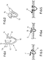
- Figures from 3 to 5 show a mounting sequence for the clip.
- the clip is bent and inserted into the hole: it is to be hold by its tongue 16 and pushed, as indicated by the arrow F, in a direction which is basically perpendicular to the plane in which the hole is.
- the clip Being still hold by its tongue 16, the clip is then pushed laterally in the direction indicated by the arrow G, so that it takes a vertical position before being further pushed into a definitive vertical position, according to the arrow H, intended to insert the clip completely and lock the finishing element.
- the operations described above, starting from the right positioning, are facilitated by the presence of the part 20 which is perpendicular to the part 18 of the tongue 16 thanks to which the L-shaped section is possible to be achieved.
Landscapes
- Engineering & Computer Science (AREA)
- General Engineering & Computer Science (AREA)
- Mechanical Engineering (AREA)
- Clamps And Clips (AREA)
- Connection Of Plates (AREA)
Abstract
Description
- The present invention refers to a locking clip made of plastic material and of the type used on motor-vehicles in order to snap lock finishing parts of the internal bodywork.
- It is quite frequent that this type of clip is not perfectly symmetrical so that it is necessary to mount it according with a defined direction and problems can arise for operator in charge. Besides, these clips present a superficial part with no protuberances on it so that it is more difficult to handle them.
- It is an object of the present invention to make it easy to catch, handle and press the clip with the hands before it is inserted.
- It is a further object of the present invention to make it easier to use this kind of clips by inserting a mark indicating the direction in which they have to be mounted.
- These and further advantages of the invention will become clear from the following description referring to the appended drawings provided as non-restrictive example and in which:
- figure 1 is a front view of the clip according to the invention;
- figure 2 is a perspective view of the clip in figure 1, and
- figures from 3 to 5 illustrate the sequence of the operations required for the mounting of the clip of figure 1 in a hole made on the support.
-
- With reference to the figures, and in particular to figures 1 and 2,
reference number 8 indicates a clip consisting of astrip 10, preferably made of plastic material, the clip presenting reduced width and being folded as to form a V. At the sides of said V there arerecesses 12 which allow to better fit the clip in its seat and especially to keep it in its position once it has been placed there. The ends of the V are provided with twotongues 14 to lock the component to be mounted on the base where theclip 10 is secured. The plant and the section of thefirst tongue 14 are basically rectangular in shape, the tongue being connected by one of its faces to the end of one of the sides of thestrip 10 which is folded in order to form a V. Thesecond tongue 16 consists of two half-parts - Similarly to the first tongue, the
tongue 16 is connected to the end of the other side of the V-shaped strip by means of one of its half-parts 18, so that the other half-part 20 is directed upwards and towards the far part of thefirst tongue 14. The half-part 20 is also folded outwards in order to guarantee a grip. - Figures from 3 to 5 show a mounting sequence for the clip. The clip is bent and inserted into the hole: it is to be hold by its
tongue 16 and pushed, as indicated by the arrow F, in a direction which is basically perpendicular to the plane in which the hole is. Being still hold by itstongue 16, the clip is then pushed laterally in the direction indicated by the arrow G, so that it takes a vertical position before being further pushed into a definitive vertical position, according to the arrow H, intended to insert the clip completely and lock the finishing element. The operations described above, starting from the right positioning, are facilitated by the presence of thepart 20 which is perpendicular to thepart 18 of thetongue 16 thanks to which the L-shaped section is possible to be achieved.
Claims (2)
- Locking clip of the type used on motor-vehicles in order to snap lock finishing parts of the bodywork, consisting of a strip (10) preferably made of plastic, folded as to form a V the ends of which V are provided with tongues (14, 16) which are basically perpendicular to said ends, characterised in that said tongues present a plant which is basically rectangular in shape, the section of one of them being basically L-shaped.
- Clip as claimed in claim 1, characterised in that the tongue, the section of which is basically L-shaped, consists of two half-part (18, 20) of basically rectangular plant, the two half-parts being perpendicularly jointed between them along one of their edges.
Applications Claiming Priority (2)
| Application Number | Priority Date | Filing Date | Title |
|---|---|---|---|
| ITTO000107U | 2000-06-22 | ||
| IT2000TO000107 IT249539Y1 (en) | 2000-06-22 | 2000-06-22 | LOCKING CLAMP IN PLASTIC MATERIAL. |
Publications (2)
| Publication Number | Publication Date |
|---|---|
| EP1167124A2 true EP1167124A2 (en) | 2002-01-02 |
| EP1167124A3 EP1167124A3 (en) | 2002-01-23 |
Family
ID=11457366
Family Applications (1)
| Application Number | Title | Priority Date | Filing Date |
|---|---|---|---|
| EP01112659A Withdrawn EP1167124A3 (en) | 2000-06-22 | 2001-05-25 | Locking clip made of plastic material |
Country Status (2)
| Country | Link |
|---|---|
| EP (1) | EP1167124A3 (en) |
| IT (1) | IT249539Y1 (en) |
Family Cites Families (4)
| Publication number | Priority date | Publication date | Assignee | Title |
|---|---|---|---|---|
| US2659950A (en) * | 1950-08-14 | 1953-11-24 | Charles D West | Trim molding fastening means and method |
| JPS57101115A (en) * | 1980-12-12 | 1982-06-23 | Nifco Inc | Fastening equipment made of synthetic resin |
| DE3937673A1 (en) * | 1988-11-24 | 1990-05-31 | Volkswagen Ag | Two-armed sprung clamp - has first V=shaped section with angled arms, and second and third sections |
| JPH09265915A (en) * | 1996-03-29 | 1997-10-07 | Nec Kansai Ltd | Inner shield coupling clamp |
-
2000
- 2000-06-22 IT IT2000TO000107 patent/IT249539Y1/en active
-
2001
- 2001-05-25 EP EP01112659A patent/EP1167124A3/en not_active Withdrawn
Non-Patent Citations (1)
| Title |
|---|
| None |
Also Published As
| Publication number | Publication date |
|---|---|
| ITTO20000107U1 (en) | 2001-12-22 |
| EP1167124A3 (en) | 2002-01-23 |
| ITTO20000107V0 (en) | 2000-06-22 |
| IT249539Y1 (en) | 2003-05-19 |
Similar Documents
| Publication | Publication Date | Title |
|---|---|---|
| US4564165A (en) | Attaching device | |
| JP5031904B2 (en) | Fixing tool for fixing the mounting member to the support member, and fixing device including the fixing tool | |
| EP0387030A2 (en) | Sign assembly | |
| US5419443A (en) | Holder for tools and other objects | |
| JP3006114U (en) | Coupling clasp and drawer with coupling clasp | |
| US20090266952A1 (en) | Magnetic Organizer | |
| EP1167124A2 (en) | Locking clip made of plastic material | |
| US6055757A (en) | Picture frame | |
| KR20170140312A (en) | Fixing the car seat cover to the foam cushion | |
| JP4331651B2 (en) | Mall mounting tool for mounting the molding between the window glass and the car body | |
| GB1583479A (en) | Clip for a butt joint | |
| JP3093082B2 (en) | Vehicle mounting clips | |
| JPH09222109A (en) | Clip for fixing resin molded parts | |
| US5197167A (en) | Trim fastenings | |
| JP2552581Y2 (en) | Clip for mounting vehicle parts | |
| JPH0738212Y2 (en) | Small parts holding box for construction | |
| EP3975803B1 (en) | Curtain hook | |
| GB1571672A (en) | Band clamp fastening | |
| EP0595463A1 (en) | Retainer for trunk lid torsion bars | |
| EP1518715A1 (en) | A paper-clip, particulary for use in motor vehicles | |
| JP3022529U (en) | Binding device | |
| JPS5923329Y2 (en) | Operation member | |
| JPS6029537Y2 (en) | Crosspiece mounting device | |
| JPH055793Y2 (en) | ||
| JPH07265144A (en) | Sleeve rail attachment mechanism to the cabinet body |
Legal Events
| Date | Code | Title | Description |
|---|---|---|---|
| PUAI | Public reference made under article 153(3) epc to a published international application that has entered the european phase |
Free format text: ORIGINAL CODE: 0009012 |
|
| PUAL | Search report despatched |
Free format text: ORIGINAL CODE: 0009013 |
|
| AK | Designated contracting states |
Kind code of ref document: A2 Designated state(s): DE ES FR GB SE Kind code of ref document: A2 Designated state(s): AT BE CH CY DE DK ES FI FR GB GR IE IT LI LU MC NL PT SE TR |
|
| AX | Request for extension of the european patent |
Free format text: AL;LT;LV;MK;RO;SI |
|
| AK | Designated contracting states |
Kind code of ref document: A3 Designated state(s): AT BE CH CY DE DK ES FI FR GB GR IE IT LI LU MC NL PT SE TR |
|
| AX | Request for extension of the european patent |
Free format text: AL;LT;LV;MK;RO;SI |
|
| RIC1 | Information provided on ipc code assigned before grant |
Free format text: 7B 60R 13/02 A, 7F 16B 5/12 B, 7F 16B 5/06 B |
|
| 17P | Request for examination filed |
Effective date: 20020627 |
|
| AKX | Designation fees paid |
Free format text: DE ES FR GB SE |
|
| 17Q | First examination report despatched |
Effective date: 20030801 |
|
| STAA | Information on the status of an ep patent application or granted ep patent |
Free format text: STATUS: THE APPLICATION IS DEEMED TO BE WITHDRAWN |
|
| 18D | Application deemed to be withdrawn |
Effective date: 20031212 |