EP1167085A1 - Dispositif et procédé perfectionnés de surveillance de la pression d'un pneu - Google Patents
Dispositif et procédé perfectionnés de surveillance de la pression d'un pneu Download PDFInfo
- Publication number
- EP1167085A1 EP1167085A1 EP01401645A EP01401645A EP1167085A1 EP 1167085 A1 EP1167085 A1 EP 1167085A1 EP 01401645 A EP01401645 A EP 01401645A EP 01401645 A EP01401645 A EP 01401645A EP 1167085 A1 EP1167085 A1 EP 1167085A1
- Authority
- EP
- European Patent Office
- Prior art keywords
- signal
- pressure
- wheel
- monitoring
- rotation
- Prior art date
- Legal status (The legal status is an assumption and is not a legal conclusion. Google has not performed a legal analysis and makes no representation as to the accuracy of the status listed.)
- Granted
Links
- 238000012544 monitoring process Methods 0.000 title claims abstract description 41
- 238000000034 method Methods 0.000 title claims abstract description 34
- 230000006870 function Effects 0.000 claims description 33
- 238000012545 processing Methods 0.000 claims description 20
- 230000001419 dependent effect Effects 0.000 claims description 14
- 238000012806 monitoring device Methods 0.000 claims description 14
- 238000005259 measurement Methods 0.000 claims description 13
- 230000000737 periodic effect Effects 0.000 claims description 11
- 238000001914 filtration Methods 0.000 claims description 8
- 230000001133 acceleration Effects 0.000 claims description 7
- 230000005540 biological transmission Effects 0.000 claims description 7
- 230000004044 response Effects 0.000 claims description 2
- 230000005484 gravity Effects 0.000 abstract description 2
- 229920000297 Rayon Polymers 0.000 description 2
- 230000003321 amplification Effects 0.000 description 2
- 238000013459 approach Methods 0.000 description 2
- 238000004364 calculation method Methods 0.000 description 2
- 238000010586 diagram Methods 0.000 description 2
- 238000003199 nucleic acid amplification method Methods 0.000 description 2
- 239000002964 rayon Substances 0.000 description 2
- 238000012795 verification Methods 0.000 description 2
- 230000003247 decreasing effect Effects 0.000 description 1
- 230000007547 defect Effects 0.000 description 1
- 238000007781 pre-processing Methods 0.000 description 1
- 230000000717 retained effect Effects 0.000 description 1
- 238000007493 shaping process Methods 0.000 description 1
- 230000008054 signal transmission Effects 0.000 description 1
Images
Classifications
-
- B—PERFORMING OPERATIONS; TRANSPORTING
- B60—VEHICLES IN GENERAL
- B60C—VEHICLE TYRES; TYRE INFLATION; TYRE CHANGING; CONNECTING VALVES TO INFLATABLE ELASTIC BODIES IN GENERAL; DEVICES OR ARRANGEMENTS RELATED TO TYRES
- B60C23/00—Devices for measuring, signalling, controlling, or distributing tyre pressure or temperature, specially adapted for mounting on vehicles; Arrangement of tyre inflating devices on vehicles, e.g. of pumps or of tanks; Tyre cooling arrangements
- B60C23/02—Signalling devices actuated by tyre pressure
- B60C23/04—Signalling devices actuated by tyre pressure mounted on the wheel or tyre
- B60C23/0408—Signalling devices actuated by tyre pressure mounted on the wheel or tyre transmitting the signals by non-mechanical means from the wheel or tyre to a vehicle body mounted receiver
-
- B—PERFORMING OPERATIONS; TRANSPORTING
- B60—VEHICLES IN GENERAL
- B60C—VEHICLE TYRES; TYRE INFLATION; TYRE CHANGING; CONNECTING VALVES TO INFLATABLE ELASTIC BODIES IN GENERAL; DEVICES OR ARRANGEMENTS RELATED TO TYRES
- B60C23/00—Devices for measuring, signalling, controlling, or distributing tyre pressure or temperature, specially adapted for mounting on vehicles; Arrangement of tyre inflating devices on vehicles, e.g. of pumps or of tanks; Tyre cooling arrangements
- B60C23/02—Signalling devices actuated by tyre pressure
- B60C23/04—Signalling devices actuated by tyre pressure mounted on the wheel or tyre
- B60C23/0408—Signalling devices actuated by tyre pressure mounted on the wheel or tyre transmitting the signals by non-mechanical means from the wheel or tyre to a vehicle body mounted receiver
- B60C23/0474—Measurement control, e.g. setting measurement rate or calibrating of sensors; Further processing of measured values, e.g. filtering, compensating or slope monitoring
-
- B—PERFORMING OPERATIONS; TRANSPORTING
- B60—VEHICLES IN GENERAL
- B60C—VEHICLE TYRES; TYRE INFLATION; TYRE CHANGING; CONNECTING VALVES TO INFLATABLE ELASTIC BODIES IN GENERAL; DEVICES OR ARRANGEMENTS RELATED TO TYRES
- B60C23/00—Devices for measuring, signalling, controlling, or distributing tyre pressure or temperature, specially adapted for mounting on vehicles; Arrangement of tyre inflating devices on vehicles, e.g. of pumps or of tanks; Tyre cooling arrangements
- B60C23/02—Signalling devices actuated by tyre pressure
- B60C23/04—Signalling devices actuated by tyre pressure mounted on the wheel or tyre
- B60C23/0486—Signalling devices actuated by tyre pressure mounted on the wheel or tyre comprising additional sensors in the wheel or tyre mounted monitoring device, e.g. movement sensors, microphones or earth magnetic field sensors
- B60C23/0488—Movement sensor, e.g. for sensing angular speed, acceleration or centripetal force
Definitions
- the present invention relates, in general and according to one of its aspects, a device making it possible to continuously monitor the pressure of a tire fitted a wheel of a motor vehicle.
- the invention relates in particular to a tire pressure monitoring device fitted to a wheel of a motor vehicle, of the type of those that include an on-board pressure sensor the wheel and delivering a representative pressure signal tire pressure, also an emission circuit on board the wheel and transmitting a signal tire pressure monitoring, and a circuit reception installed on a part of the vehicle carried by the wheel, to receive the monitoring signal.
- the signal of monitoring is transmitted to the receiving circuit, and this the latter is designed to deliver an alert signal when the tire pressure is insufficient.
- the transmission circuit is on board the wheel and can only be easily powered by a battery, the high frequency of signal transmission from surveillance only allows relatively autonomy low of this stack.
- one of the purposes of this invention is to provide a device using a transmitter on the wheel which, even if it is powered by a battery, has increased autonomy.
- the device of the invention by elsewhere conforms to the generic definition given by it the preamble above, is essentially characterized in that it further comprises processing means embarked on the wheel to make the signal of at least partially signal dependent monitoring pressure and a pressure setpoint signal.
- this device further comprises a wheel rotation sensor on the wheel and producing a wheel rotation signal, and the means are designed to make the signal pressure setpoint at least partially dependent on the wheel rotation signal.
- the rotation sensor comprises for example a accelerometer with a sensitive axis at an angle not zero with a horizontal direction.
- the processing means can advantageously include a first function generator delivering, to from the rotation signal, a setpoint signal of pressure linked to the rotation signal by an increasing law with vehicle speed, and a second generator function producing, as a monitoring signal, a signal related to a difference between the signal of pressure and the pressure setpoint signal.
- the rotation sensor includes a high pass filter connected to the accelerometer and providing a filtered signal substantially periodic.
- the rotation sensor includes a low-pass filter connected to the accelerometer and providing a filtered signal substantially continuous.
- the rotation sensor can include a circuit formatting producing, as a rotation signal of wheel, a signal representing the period, frequency, or the amplitude of the filtered signal.
- the first function generator can include a comparator to produce the signal pressure setpoint in response to a comparison between the wheel rotation signal and at least one threshold.
- the first function generator can include a memory containing at least two values different from the pressure setpoint signal, accessible at different addresses in the memory, and an addressing circuit using the rotation signal of wheel as a read address in memory.
- the second function generator can produce, as monitoring signal, a signal representing at least the sign of the difference between the pressure signal and the pressure setpoint signal.
- the transmission circuit transmits the monitoring signal only provided that the difference between the signal of pressure and the pressure setpoint signal either negative.
- the pressure setpoint signal takes a value chosen from at least two different discrete values one from the other.
- the invention also relates to a method of monitoring the pressure of a tire fitted to a wheel of a motor vehicle, this method comprising a first measurement procedure implemented on the wheel and consisting in delivering a representative pressure signal tire pressure, a transmission operation implementation on the wheel and consisting in emitting a tire pressure monitoring signal, and a reception operation, implemented on part of the vehicle carried by the wheel, and consisting in receiving the surveillance signal, this process being essentially characterized in that it further comprises a procedure processing implemented on the wheel and consisting of make the monitoring signal at least partially dependent on the pressure signal and a signal pressure setpoint.
- the method of the invention comprises in addition a second measurement procedure implemented on the wheel and consisting in delivering a signal of wheel rotation, the treatment procedure being set implemented to return the pressure setpoint signal to the less partially dependent on the rotation signal of wheel.
- the second measurement procedure can for example understand an operation consisting in delivering a signal dependent on a non-zero acceleration undergone at a point wheel measurement.
- the treatment procedure can meanwhile understand a first processing step consisting of issue, from the rotation signal, a signal pressure setpoint linked to the rotation signal by a law increasing with vehicle speed, and a second processing step consisting in delivering, as surveillance signal, a signal linked to a difference between the pressure signal and the setpoint signal pressure.
- the second measurement procedure includes an operation of high pass filtering performed on the signal dependent on acceleration of the measuring point, this operation of high pass filtering providing a filtered signal substantially periodic, and the first step in processing includes a comparison operation of comparing the period or frequency of substantially periodic filtered signal to at least one reference period or frequency.
- the second measurement procedure includes an operation of low-pass filtering performed on the signal dependent on acceleration of the measuring point, this operation of low pass filtering providing a filtered signal substantially continuous, and the first stage of treatment includes a comparison operation consisting of compare the amplitude of the filtered signal significantly continuous at least one reference amplitude.
- the second processing step consists for example in delivering, in as a monitoring signal, a signal representing at least the sign of the difference between the signal of pressure and the pressure setpoint signal, the transmission operation being carried out only for as long as this difference is negative.
- the invention in one of its aspects, relates to a tire pressure monitoring device fitted to a wheel of a motor vehicle.
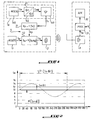
- this device includes essentially, in known manner, a pressure sensor 1 on the wheel, an emission circuit 2 also on board the wheel, and a receiving circuit 3 installed on the vehicle chassis or any part carried by the wheels.
- the pressure sensor 1, for example installed on the tire valve of the wheel concerned has the function of deliver a pressure signal Sp representative of the pressure of this tire, the emission circuit 2 having for function of transmitting to reception circuit 3 a monitoring signal Ss linked to tire pressure.
- the device of the invention is distinguished from devices known in that it further comprises means of treatment generically designated by the reference 5, on board the wheel, and intended to render the monitoring signal Ss at least partially dependent on the pressure signal Sp delivered by the sensor 1, and a predetermined pressure setpoint signal Kp.
- this device further includes a wheel rotation sensor, generically designated by reference 4, too on the wheel, and capable of producing a signal wheel rotation Sr, the processing means 5 being then designed to make the setpoint signal of pressure Kp at least partially dependent on the signal wheel rotation Sr.
- a wheel rotation sensor generically designated by reference 4, too on the wheel, and capable of producing a signal wheel rotation Sr, the processing means 5 being then designed to make the setpoint signal of pressure Kp at least partially dependent on the signal wheel rotation Sr.
- the rotation sensor 4 comprises a accelerometer 40 rotating with the wheel and having a sensitive axis arranged in a vertical plane.
- the device of the invention can be designed for exploit one or other of the periodic components and of the accelerometer output signal Sa, these two possibilities being illustrated simultaneously on the figure 1.
- the output signal Sa of the accelerometer 40 is operated via its periodic component Sa ⁇ 1
- this component is produced by a high-pass filter 41 integrated into the rotation 4 and connected to the output of the accelerometer 40.
- the output signal Sa of the accelerometer 40 is operated via its continuous component Sa ⁇ 2, this component is produced by a low-pass filter 42 integrated into the rotation sensor 4 and connected to the output of the accelerometer 40.
- the rotation sensor 4 further comprises a formatting circuit 43 which, whatever the solution retained, produces a wheel rotation signal Sr at from the filtered signal Sa ⁇ 1 or Sa ⁇ 2 which it receives, this signal being generically noted Sa ⁇ .
- this circuit 43 has by example for the function of producing, as a signal wheel rotation Sr, a signal representing the frequency or the period of this filtered signal Sa ⁇ 1, that is to say F (Sa ⁇ 1) or 1 / F (Sa ⁇ 1).
- this circuit 43 has for example the function of producing, as wheel rotation signal Sr, a signal representing the amplitude of the filtered signal Sa ⁇ 2, that is to say M (Sa ⁇ 2).
- tire pressure should be higher as the vehicle speed is high, so that limit the deformations suffered by the tires by continuation of the increasing demands which apply to them.
- the first function generator 51 calculates the speed V of the vehicle from the known values of the parameters k, r, R, and the rotation signal Sr represented by the signals F (Sa ⁇ 1), 1 / F (Sa ⁇ 1) or M (Sa ⁇ 2), and choose a pressure setpoint Kp as a function of this speed V.
- the first function generator 51 choose a pressure setpoint value Kp directly as a function of the rotation signal Sr, i.e. directly as a function of the signals F (Sa ⁇ 1), 1 / F (Sa ⁇ 1) or M (Sa ⁇ 2), this approach making it possible to avoid the calculation of the speed V of the vehicle.
- the first function generator 51 can for example understand at least a first comparator suitable for comparing the wheel rotation signal Sr to a first threshold Sr1 and to be produced, as a signal output Kp, a signal of value Kp1 or of value Kp2 according to that the wheel rotation signal Sr is at most equal to the first threshold Sr1, or that it is higher, the value Kp1 being less than the value Kp2 if the signal Sr is represented by an increasing function of the speed V of the vehicle, as in the case of F (Sa ⁇ 1) and M (Sa ⁇ 2), the Kp1 value, on the other hand, is greater than Kp2 value if the signal Sr is represented by a function decreasing vehicle speed V, as is the case of 1 / F (Sa ⁇ 1).
- a first comparator suitable for comparing the wheel rotation signal Sr to a first threshold Sr1 and to be produced, as a signal output Kp, a signal of value Kp1 or of value Kp2 according to that the wheel rotation signal Sr is at most equal to
- the first function generator 51 can include several comparators to be able to compare the signal of wheel rotation Sr with several thresholds such as Sr1 and to correlatively produce as many signal values pressure setpoint Kp as logical states likely to be taken by these comparators.
- the first function generator 51 can include a calculation module suitable for calculating the value of the signal pressure setpoint Kp as a function of the rotation signal wheel Sr and a pre-established algorithm.
- the first function generator 51 can include a memory containing at least two different values Kp1 and Kp2 of the pressure setpoint signal Kp, accessible at different addresses in memory, and a circuit which uses the wheel rotation signal Sr as a read address in this memory.
- the device of the invention comprises a second generator 52 which receives both the setpoint signal pressure Kp and the pressure signal Sp from the pressure sensor 1, and which outputs a signal constituting the monitoring signal Ss and represented by a function h (Sp, Kp) of the signals Sp and Kp.
- the function generator 52 produces, as a signal monitoring Ss, a signal linked to the difference Sp-Kp between the pressure signal Sp and the setpoint signal pressure Kp.
- the second function generator 52 can produce, as monitoring signal Ss, a signal which represents the difference Sp-Kp between the signal of pressure Sp and the pressure setpoint signal Kp, or a signal that only represents the sign of this difference.
- the monitoring signal Ss is sent towards receiver 3 located on the vehicle chassis automobile and then transmitted at least indirectly to a display device 32.
- this signal can first be transmitted to a pre-processing circuit 31, capable of evaluating, in particular depending on the speed V of the vehicle, the severity of any tire pressure defect and control the display device 32 so more or less pressing depending on the severity of the fault detected.
- the invention also relates to a method of monitoring the pressure of a tire fitted to a wheel of a motor vehicle, this method comprising, as that elementary operations, the implementation of functions as previously described, individually and collectively, in their nature and in their arrangement.
Landscapes
- Engineering & Computer Science (AREA)
- Mechanical Engineering (AREA)
- Measuring Fluid Pressure (AREA)
- Arrangements For Transmission Of Measured Signals (AREA)
Abstract
Description
- La Figure 1 est un schéma représentant, sous forme fonctionnelle, les circuits utilisés dans le dispositif de l'invention, les fonctions réalisées par ces circuits constituant les opérations du procédé de l'invention; et
- La Figure 2 est un diagramme temporel représentant le signal de sortie d'un accéléromètre susceptible d'être utilisé dans l'invention.
Claims (19)
- Dispositif de surveillance de la pression d'un pneu équipant une roue d'un véhicule automobile, comprenant un capteur de pression (1) embarqué sur la roue et délivrant un signal de pression (Sp) représentatif de la pression du pneu, un circuit d'émission (2) également embarqué sur la roue et transmettant un signal de surveillance (Ss) lié à la pression du pneu, et un circuit de réception (3) installé sur une partie du véhicule portée par la roue, pour recevoir le signal de surveillance (Ss), caractérisé en ce qu'il comprend en outre des moyens de traitement (5) embarqués sur la roue pour rendre le signal de surveillance (Ss) au moins partiellement dépendant du signal de pression (Sp) et d'un signal de consigne de pression (Kp).
- Dispositif de surveillance suivant la revendication 1, caractérisé en ce qu'il comprend en outre un capteur de rotation de la roue (4) embarqué sur la roue et produisant un signal de rotation de roue (Sr), et en ce que les moyens de traitement (5) sont conçus pour rendre le signal de consigne de pression (Kp) au moins partiellement dépendant du signal de rotation de roue (Sr).
- Dispositif de surveillance suivant la revendication 2, caractérisé en ce que le capteur de rotation (4) comprend un accéléromètre (40) présentant un axe sensible faisant un angle non nul avec une direction horizontale.
- Dispositif de surveillance suivant l'une quelconque des revendications 2 et 3, caractérisé en ce que les moyens de traitement (5) comprennent un premier générateur de fonction (51) délivrant, à partir du signal de rotation (Sr), un signal de consigne de pression (Kp) lié au signal de rotation (Sr) par une loi croissant avec la vitesse du véhicule, et un second générateur de fonction (52) produisant, en tant que signal de surveillance (Ss), un signal lié à une différence (Sp-Kp) entre le signal de pression (Sp) et le signal de consigne de pression (Kp).
- Dispositif de surveillance suivant l'une quelconque des revendications précédentes combinée à la revendication 3, caractérisé en ce que le capteur de rotation (4) comprend un filtre passe-haut (41) relié à l'accéléromètre (40) et fournissant un signal filtré (Sa1) sensiblement périodique.
- Dispositif de surveillance suivant l'une quelconque des revendications précédentes combinée à la revendication 3, caractérisé en ce que le capteur de rotation (4) comprend un filtre passe-bas (42) relié à l'accéléromètre (40) et fournissant un signal filtré (Sa2) sensiblement continu.
- Dispositif de surveillance suivant l'une quelconque des revendications 5 et 6, caractérisé en ce que le capteur de rotation (4) comprend un circuit de formatage (43) produisant, en tant que signal de rotation de roue (Sr), un signal représentant la période, la fréquence, ou l'amplitude du signal filtré.
- Dispositif de surveillance suivant les revendications 4 et 7, caractérisé en ce que le premier générateur de fonction (51) comprend un comparateur pour produire le signal de consigne de pression (Kp) en réponse à une comparaison entre le signal de rotation de roue (Sr) et au moins un seuil.
- Dispositif de surveillance suivant les revendications 4 et 7, caractérisé en ce que le premier générateur de fonction (51) comprend une mémoire contenant au moins deux valeurs différentes du signal de consigne de pression (Kp), accessibles à des adresses différentes de la mémoire, et un circuit d'adressage utilisant le signal de rotation de roue (Sr) en tant qu'adresse de lecture dans la mémoire.
- Dispositif de surveillance suivant l'une quelconque des revendications précédentes combinée à la revendication 4, caractérisé en ce que le second générateur de fonction (52) produit, en tant que signal de surveillance (Ss), un signal représentant au moins le signe de la différence (Sp-Kp) entre le signal de pression (Sp) et le signal de consigne de pression (Kp).
- Dispositif de surveillance suivant la revendication 10, caractérisé en ce que le circuit d'émission (2) n'émet le signal de surveillance (Ss) que sous condition que la différence (Sp-Kp) entre le signal de pression (Sp) et le signal de consigne de pression (Kp) soit négative.
- Dispositif de surveillance suivant l'une quelconque des revendications précédentes combinée à la revendication 4, caractérisé en ce que le signal de consigne de pression (Kp) prend une valeur choisie parmi au moins deux valeurs discrètes (Kpl, Kp2) différentes l'une de l'autre.
- Procédé de surveillance de la pression d'un pneu équipant une roue d'un véhicule automobile, comprenant une première procédure de mesure mise en oeuvre sur la roue et consistant à délivrer un signal de pression (Sp) représentatif de la pression du pneu, une opération de transmission mise en oeuvre sur la roue et consistant à émettre un signal de surveillance (Ss) lié à la pression du pneu, et une opération de réception, mise en oeuvre sur une partie du véhicule portée par la roue, et consistant à recevoir le signal de surveillance (Ss), caractérisé en ce qu'il comprend en outre une procédure de traitement mise en oeuvre sur la roue et consistant à rendre le signal de surveillance (Ss) au moins partiellement dépendant du signal de pression (Sp) et d'un signal de consigne de pression (Kp).
- Procédé suivant la revendication 13, caractérisé en ce qu'il comprend en outre une seconde procédure de mesure mise en oeuvre sur la roue et consistant à délivrer un signal de rotation de roue (Sr), et en ce que la procédure de traitement est mise en oeuvre pour rendre le signal de consigne de pression (Kp) au moins partiellement dépendant du signal de rotation de roue (Sr).
- Procédé de surveillance suivant la revendication 14, caractérisé en ce que la seconde procédure de mesure comprend une opération consistant à délivrer un signal (Sa) dépendant d'une accélération non nulle subie en un point de mesure de la roue.
- Procédé de surveillance suivant l'une quelconque des revendications 14 et 15, caractérisé en ce que la procédure de traitement comprend une première étape de traitement consistant à délivrer, à partir du signal de rotation (Sr), un signal de consigne de pression (Kp) lié au signal de rotation (Sr) par une loi croissant avec la vitesse du véhicule, et une seconde étape de traitement consistant à délivrer, en tant que signal de surveillance (Ss), un signal lié à une différence (Sp-Kp) entre le signal de pression (Sp) et le signal de consigne de pression (Kp).
- Procédé de surveillance suivant les revendications 15 et 16, caractérisé en ce que la seconde procédure de mesure comprend une opération de filtrage passe-haut effectuée sur le signal (Sa) dépendant de l'accélération du point de mesure, cette opération de filtrage passe-haut fournissant un signal filtré (Sa1) sensiblement périodique, et en ce que la première étape de traitement comprend une opération de comparaison consistant à comparer la période ou la fréquence du signal filtré sensiblement périodique à au moins une période ou une fréquence de référence.
- Procédé de surveillance suivant les revendications 15 et 16, caractérisé en ce que la seconde procédure de mesure comprend une opération de filtrage passe-bas effectuée sur le signal (Sa) dépendant de l'accélération du point de mesure, cette opération de filtrage passe-bas fournissant un signal filtré (Sa2) sensiblement continu, et en ce que la première étape de traitement comprend une opération de comparaison consistant à comparer l'amplitude du signal filtré sensiblement continu à au moins une amplitude de référence.
- Procédé de surveillance suivant l'une quelconque des revendications 13 à 18 combinée à la revendication 16, caractérisé en ce que la seconde étape de traitement consiste à délivrer, en tant que signal de surveillance (Ss), un signal représentant au moins le signe de la différence (Sp-Kp) entre le signal de pression (Sp) et le signal de consigne de pression (Kp), et en ce que l'opération de transmission n'est effectuée que pour autant que cette différence soit négative.
Applications Claiming Priority (2)
| Application Number | Priority Date | Filing Date | Title |
|---|---|---|---|
| FR0008161A FR2810584B1 (fr) | 2000-06-26 | 2000-06-26 | Dispositif et procede perfectionnes de surveillance de la pression d'un pneu |
| FR0008161 | 2000-06-26 |
Publications (2)
| Publication Number | Publication Date |
|---|---|
| EP1167085A1 true EP1167085A1 (fr) | 2002-01-02 |
| EP1167085B1 EP1167085B1 (fr) | 2006-05-24 |
Family
ID=8851670
Family Applications (1)
| Application Number | Title | Priority Date | Filing Date |
|---|---|---|---|
| EP01401645A Expired - Lifetime EP1167085B1 (fr) | 2000-06-26 | 2001-06-21 | Dispositif et procédé perfectionnés de surveillance de la pression d'un pneu |
Country Status (5)
| Country | Link |
|---|---|
| EP (1) | EP1167085B1 (fr) |
| AT (1) | ATE327112T1 (fr) |
| DE (1) | DE60119836T2 (fr) |
| ES (1) | ES2263569T3 (fr) |
| FR (1) | FR2810584B1 (fr) |
Cited By (1)
| Publication number | Priority date | Publication date | Assignee | Title |
|---|---|---|---|---|
| WO2006108869A1 (fr) * | 2005-04-13 | 2006-10-19 | Societe De Technologie Michelin | Procédé et dispositif de surveillance de la pression d'un pneumatique |
Citations (1)
| Publication number | Priority date | Publication date | Assignee | Title |
|---|---|---|---|---|
| US5963128A (en) * | 1994-11-22 | 1999-10-05 | Schrader-Bridgeport International, Inc. | Remote tire pressure monitoring system |
-
2000
- 2000-06-26 FR FR0008161A patent/FR2810584B1/fr not_active Expired - Fee Related
-
2001
- 2001-06-21 AT AT01401645T patent/ATE327112T1/de not_active IP Right Cessation
- 2001-06-21 EP EP01401645A patent/EP1167085B1/fr not_active Expired - Lifetime
- 2001-06-21 ES ES01401645T patent/ES2263569T3/es not_active Expired - Lifetime
- 2001-06-21 DE DE60119836T patent/DE60119836T2/de not_active Expired - Lifetime
Patent Citations (1)
| Publication number | Priority date | Publication date | Assignee | Title |
|---|---|---|---|---|
| US5963128A (en) * | 1994-11-22 | 1999-10-05 | Schrader-Bridgeport International, Inc. | Remote tire pressure monitoring system |
Cited By (4)
| Publication number | Priority date | Publication date | Assignee | Title |
|---|---|---|---|---|
| WO2006108869A1 (fr) * | 2005-04-13 | 2006-10-19 | Societe De Technologie Michelin | Procédé et dispositif de surveillance de la pression d'un pneumatique |
| FR2884455A1 (fr) * | 2005-04-13 | 2006-10-20 | Michelin Soc Tech | Procede et dispositif de surveillance de la pression d'un pneumatique |
| CN101189136B (zh) * | 2005-04-13 | 2010-12-01 | 米其林技术公司 | 监测轮胎压力的方法和装置 |
| US8011236B2 (en) | 2005-04-13 | 2011-09-06 | Michelin Recherche Et Technique, S.A. | Method and device for monitoring tire pressure utilizing a reference value that evolves according to a predetermined function of time |
Also Published As
| Publication number | Publication date |
|---|---|
| DE60119836T2 (de) | 2006-12-21 |
| FR2810584A1 (fr) | 2001-12-28 |
| FR2810584B1 (fr) | 2002-10-18 |
| ATE327112T1 (de) | 2006-06-15 |
| EP1167085B1 (fr) | 2006-05-24 |
| DE60119836D1 (de) | 2006-06-29 |
| ES2263569T3 (es) | 2006-12-16 |
Similar Documents
| Publication | Publication Date | Title |
|---|---|---|
| EP1593532B1 (fr) | Système de controle de la pression des pneumatiques des roues d'un véhicule automobile | |
| EP2655102B1 (fr) | Procede et dispositif d'echantillonnage de mesures d'acceleration d'une roue d'un vehicule automobile | |
| FR2913371A1 (fr) | Procede et systeme de controle des pneus. | |
| FR2880953A1 (fr) | Capteur de roue pour detecter un mouvement du vehicule | |
| WO2001090714A2 (fr) | Methode de determination de composantes d'efforts subis par un pneumatique | |
| WO2003051652A1 (fr) | Systeme de controle de la pression des pneumatiques des roues d'un vehicule | |
| EP0539263B1 (fr) | Procédé et dispositif de freinage de véhicules par asservissement du couple de freinage appliqué sur une roue | |
| FR3072524B1 (fr) | Procede d’autolocalisation des capteurs equipant les roues d’un vehicule | |
| EP1167085B1 (fr) | Dispositif et procédé perfectionnés de surveillance de la pression d'un pneu | |
| FR3069192B1 (fr) | Procede de localisation d'une position de chaque roue d'un vehicule automobile associee a un boitier electronique | |
| EP2303608A1 (fr) | Procede et dispositif de detection de perte de pression dans les pneumatiques | |
| FR2958586A1 (fr) | Systeme de commande d'un actionneur de transfert de couple a modes de fonctionnement multiples. | |
| WO2016181064A1 (fr) | Procédé de détection du glissement d'au moins une roue de véhicule automobile | |
| FR2962939A1 (fr) | Procede de calcul d'une pression de reference, procede et dispositif associe de surveillance de la pression des pneus d'un vehicule | |
| WO2018104680A1 (fr) | Procédé de supervision de la vitesse d'un véhicule | |
| EP3077225A1 (fr) | Systeme et procede de detection indirecte du sous-gonflage d'un pneumatique | |
| EP1347308B1 (fr) | Dispositif de surveillance routière embarqué | |
| FR3000930A1 (fr) | Procede de detection de lever de roue arriere de vehicule automobile en virage | |
| FR2945122A1 (fr) | Procede et dispositif d'evaluation de l'usure d'un pneu | |
| FR2888536A1 (fr) | Procede et dispositif de limitation du temps intervehicule | |
| EP2085255B1 (fr) | Procédé de calibration d'un signal de détection de crevasion d'un pneumatique d'un véhicule | |
| EP2244235B1 (fr) | Procédé d'autocalibration d'un module de sirène d'alarme pour véhicule | |
| EP2454115A1 (fr) | Dispositif de selection d'un mode de motricite d'un vehicule a quatre roues motrices | |
| FR2923423A1 (fr) | Systeme de controle d'un couple de traction et/ou de freinage sur au moins une roue d'un vehicule terrestre a moteur electrique | |
| FR2709719A1 (fr) | Procédé d'asservissement de la vitesse angulaire d'une roue de véhicule automobile pendant une phase de freinage. |
Legal Events
| Date | Code | Title | Description |
|---|---|---|---|
| PUAI | Public reference made under article 153(3) epc to a published international application that has entered the european phase |
Free format text: ORIGINAL CODE: 0009012 |
|
| AK | Designated contracting states |
Kind code of ref document: A1 Designated state(s): AT BE CH CY DE DK ES FI FR GB GR IE IT LI LU MC NL PT SE TR |
|
| AX | Request for extension of the european patent |
Free format text: AL;LT;LV;MK;RO;SI |
|
| 17P | Request for examination filed |
Effective date: 20020620 |
|
| AKX | Designation fees paid |
Free format text: AT BE CH CY DE DK ES FI FR GB GR IE IT LI LU MC NL PT SE TR |
|
| 17Q | First examination report despatched |
Effective date: 20041117 |
|
| GRAP | Despatch of communication of intention to grant a patent |
Free format text: ORIGINAL CODE: EPIDOSNIGR1 |
|
| GRAS | Grant fee paid |
Free format text: ORIGINAL CODE: EPIDOSNIGR3 |
|
| GRAA | (expected) grant |
Free format text: ORIGINAL CODE: 0009210 |
|
| AK | Designated contracting states |
Kind code of ref document: B1 Designated state(s): AT BE CH CY DE DK ES FI FR GB GR IE IT LI LU MC NL PT SE TR |
|
| PG25 | Lapsed in a contracting state [announced via postgrant information from national office to epo] |
Ref country code: AT Free format text: LAPSE BECAUSE OF FAILURE TO SUBMIT A TRANSLATION OF THE DESCRIPTION OR TO PAY THE FEE WITHIN THE PRESCRIBED TIME-LIMIT Effective date: 20060524 Ref country code: FI Free format text: LAPSE BECAUSE OF FAILURE TO SUBMIT A TRANSLATION OF THE DESCRIPTION OR TO PAY THE FEE WITHIN THE PRESCRIBED TIME-LIMIT Effective date: 20060524 Ref country code: IE Free format text: LAPSE BECAUSE OF FAILURE TO SUBMIT A TRANSLATION OF THE DESCRIPTION OR TO PAY THE FEE WITHIN THE PRESCRIBED TIME-LIMIT Effective date: 20060524 Ref country code: NL Free format text: LAPSE BECAUSE OF FAILURE TO SUBMIT A TRANSLATION OF THE DESCRIPTION OR TO PAY THE FEE WITHIN THE PRESCRIBED TIME-LIMIT Effective date: 20060524 |
|
| REG | Reference to a national code |
Ref country code: GB Ref legal event code: FG4D Free format text: NOT ENGLISH |
|
| REG | Reference to a national code |
Ref country code: CH Ref legal event code: EP |
|
| REG | Reference to a national code |
Ref country code: IE Ref legal event code: FG4D Free format text: LANGUAGE OF EP DOCUMENT: FRENCH |
|
| REF | Corresponds to: |
Ref document number: 60119836 Country of ref document: DE Date of ref document: 20060629 Kind code of ref document: P |
|
| PG25 | Lapsed in a contracting state [announced via postgrant information from national office to epo] |
Ref country code: MC Free format text: LAPSE BECAUSE OF NON-PAYMENT OF DUE FEES Effective date: 20060630 Ref country code: CH Free format text: LAPSE BECAUSE OF NON-PAYMENT OF DUE FEES Effective date: 20060630 Ref country code: BE Free format text: LAPSE BECAUSE OF NON-PAYMENT OF DUE FEES Effective date: 20060630 Ref country code: LI Free format text: LAPSE BECAUSE OF NON-PAYMENT OF DUE FEES Effective date: 20060630 |
|
| PG25 | Lapsed in a contracting state [announced via postgrant information from national office to epo] |
Ref country code: DK Free format text: LAPSE BECAUSE OF FAILURE TO SUBMIT A TRANSLATION OF THE DESCRIPTION OR TO PAY THE FEE WITHIN THE PRESCRIBED TIME-LIMIT Effective date: 20060824 Ref country code: SE Free format text: LAPSE BECAUSE OF FAILURE TO SUBMIT A TRANSLATION OF THE DESCRIPTION OR TO PAY THE FEE WITHIN THE PRESCRIBED TIME-LIMIT Effective date: 20060824 |
|
| GBT | Gb: translation of ep patent filed (gb section 77(6)(a)/1977) |
Effective date: 20060816 |
|
| PG25 | Lapsed in a contracting state [announced via postgrant information from national office to epo] |
Ref country code: PT Free format text: LAPSE BECAUSE OF FAILURE TO SUBMIT A TRANSLATION OF THE DESCRIPTION OR TO PAY THE FEE WITHIN THE PRESCRIBED TIME-LIMIT Effective date: 20061024 |
|
| NLV1 | Nl: lapsed or annulled due to failure to fulfill the requirements of art. 29p and 29m of the patents act | ||
| REG | Reference to a national code |
Ref country code: ES Ref legal event code: FG2A Ref document number: 2263569 Country of ref document: ES Kind code of ref document: T3 |
|
| REG | Reference to a national code |
Ref country code: IE Ref legal event code: FD4D |
|
| REG | Reference to a national code |
Ref country code: CH Ref legal event code: PL |
|
| PLBE | No opposition filed within time limit |
Free format text: ORIGINAL CODE: 0009261 |
|
| STAA | Information on the status of an ep patent application or granted ep patent |
Free format text: STATUS: NO OPPOSITION FILED WITHIN TIME LIMIT |
|
| 26N | No opposition filed |
Effective date: 20070227 |
|
| BERE | Be: lapsed |
Owner name: PEUGEOT CITROEN AUTOMOBILES SA Effective date: 20060630 |
|
| REG | Reference to a national code |
Ref country code: GB Ref legal event code: 746 Effective date: 20080304 |
|
| PG25 | Lapsed in a contracting state [announced via postgrant information from national office to epo] |
Ref country code: GR Free format text: LAPSE BECAUSE OF FAILURE TO SUBMIT A TRANSLATION OF THE DESCRIPTION OR TO PAY THE FEE WITHIN THE PRESCRIBED TIME-LIMIT Effective date: 20060825 |
|
| PG25 | Lapsed in a contracting state [announced via postgrant information from national office to epo] |
Ref country code: LU Free format text: LAPSE BECAUSE OF NON-PAYMENT OF DUE FEES Effective date: 20060621 Ref country code: TR Free format text: LAPSE BECAUSE OF FAILURE TO SUBMIT A TRANSLATION OF THE DESCRIPTION OR TO PAY THE FEE WITHIN THE PRESCRIBED TIME-LIMIT Effective date: 20060524 |
|
| PGFP | Annual fee paid to national office [announced via postgrant information from national office to epo] |
Ref country code: ES Payment date: 20080606 Year of fee payment: 8 |
|
| PGFP | Annual fee paid to national office [announced via postgrant information from national office to epo] |
Ref country code: IT Payment date: 20080614 Year of fee payment: 8 |
|
| PG25 | Lapsed in a contracting state [announced via postgrant information from national office to epo] |
Ref country code: CY Free format text: LAPSE BECAUSE OF FAILURE TO SUBMIT A TRANSLATION OF THE DESCRIPTION OR TO PAY THE FEE WITHIN THE PRESCRIBED TIME-LIMIT Effective date: 20060524 |
|
| REG | Reference to a national code |
Ref country code: ES Ref legal event code: FD2A Effective date: 20090622 |
|
| PG25 | Lapsed in a contracting state [announced via postgrant information from national office to epo] |
Ref country code: ES Free format text: LAPSE BECAUSE OF NON-PAYMENT OF DUE FEES Effective date: 20090622 |
|
| PG25 | Lapsed in a contracting state [announced via postgrant information from national office to epo] |
Ref country code: IT Free format text: LAPSE BECAUSE OF NON-PAYMENT OF DUE FEES Effective date: 20090621 |
|
| PGFP | Annual fee paid to national office [announced via postgrant information from national office to epo] |
Ref country code: GB Payment date: 20110606 Year of fee payment: 11 |
|
| PGFP | Annual fee paid to national office [announced via postgrant information from national office to epo] |
Ref country code: FR Payment date: 20110727 Year of fee payment: 11 |
|
| PGFP | Annual fee paid to national office [announced via postgrant information from national office to epo] |
Ref country code: DE Payment date: 20110606 Year of fee payment: 11 |
|
| GBPC | Gb: european patent ceased through non-payment of renewal fee |
Effective date: 20120621 |
|
| REG | Reference to a national code |
Ref country code: FR Ref legal event code: ST Effective date: 20130228 |
|
| REG | Reference to a national code |
Ref country code: DE Ref legal event code: R119 Ref document number: 60119836 Country of ref document: DE Effective date: 20130101 |
|
| PG25 | Lapsed in a contracting state [announced via postgrant information from national office to epo] |
Ref country code: GB Free format text: LAPSE BECAUSE OF NON-PAYMENT OF DUE FEES Effective date: 20120621 Ref country code: DE Free format text: LAPSE BECAUSE OF NON-PAYMENT OF DUE FEES Effective date: 20130101 Ref country code: FR Free format text: LAPSE BECAUSE OF NON-PAYMENT OF DUE FEES Effective date: 20120702 |