EP1166976A2 - Paper cutting apparatus and image forming apparatus with such a paper cutting apparatus - Google Patents
Paper cutting apparatus and image forming apparatus with such a paper cutting apparatus Download PDFInfo
- Publication number
- EP1166976A2 EP1166976A2 EP01115098A EP01115098A EP1166976A2 EP 1166976 A2 EP1166976 A2 EP 1166976A2 EP 01115098 A EP01115098 A EP 01115098A EP 01115098 A EP01115098 A EP 01115098A EP 1166976 A2 EP1166976 A2 EP 1166976A2
- Authority
- EP
- European Patent Office
- Prior art keywords
- booklet
- cutting
- stopping
- conveying
- processing
- Prior art date
- Legal status (The legal status is an assumption and is not a legal conclusion. Google has not performed a legal analysis and makes no representation as to the accuracy of the status listed.)
- Granted
Links
Images







Classifications
-
- G—PHYSICS
- G03—PHOTOGRAPHY; CINEMATOGRAPHY; ANALOGOUS TECHNIQUES USING WAVES OTHER THAN OPTICAL WAVES; ELECTROGRAPHY; HOLOGRAPHY
- G03G—ELECTROGRAPHY; ELECTROPHOTOGRAPHY; MAGNETOGRAPHY
- G03G15/00—Apparatus for electrographic processes using a charge pattern
- G03G15/65—Apparatus which relate to the handling of copy material
- G03G15/6582—Special processing for irreversibly adding or changing the sheet copy material characteristics or its appearance, e.g. stamping, annotation printing, punching
-
- B—PERFORMING OPERATIONS; TRANSPORTING
- B26—HAND CUTTING TOOLS; CUTTING; SEVERING
- B26D—CUTTING; DETAILS COMMON TO MACHINES FOR PERFORATING, PUNCHING, CUTTING-OUT, STAMPING-OUT OR SEVERING
- B26D1/00—Cutting through work characterised by the nature or movement of the cutting member or particular materials not otherwise provided for; Apparatus or machines therefor; Cutting members therefor
- B26D1/01—Cutting through work characterised by the nature or movement of the cutting member or particular materials not otherwise provided for; Apparatus or machines therefor; Cutting members therefor involving a cutting member which does not travel with the work
- B26D1/04—Cutting through work characterised by the nature or movement of the cutting member or particular materials not otherwise provided for; Apparatus or machines therefor; Cutting members therefor involving a cutting member which does not travel with the work having a linearly-movable cutting member
- B26D1/06—Cutting through work characterised by the nature or movement of the cutting member or particular materials not otherwise provided for; Apparatus or machines therefor; Cutting members therefor involving a cutting member which does not travel with the work having a linearly-movable cutting member wherein the cutting member reciprocates
- B26D1/08—Cutting through work characterised by the nature or movement of the cutting member or particular materials not otherwise provided for; Apparatus or machines therefor; Cutting members therefor involving a cutting member which does not travel with the work having a linearly-movable cutting member wherein the cutting member reciprocates of the guillotine type
-
- B—PERFORMING OPERATIONS; TRANSPORTING
- B26—HAND CUTTING TOOLS; CUTTING; SEVERING
- B26D—CUTTING; DETAILS COMMON TO MACHINES FOR PERFORATING, PUNCHING, CUTTING-OUT, STAMPING-OUT OR SEVERING
- B26D7/00—Details of apparatus for cutting, cutting-out, stamping-out, punching, perforating, or severing by means other than cutting
- B26D7/01—Means for holding or positioning work
- B26D7/015—Means for holding or positioning work for sheet material or piles of sheets
-
- B—PERFORMING OPERATIONS; TRANSPORTING
- B26—HAND CUTTING TOOLS; CUTTING; SEVERING
- B26D—CUTTING; DETAILS COMMON TO MACHINES FOR PERFORATING, PUNCHING, CUTTING-OUT, STAMPING-OUT OR SEVERING
- B26D7/00—Details of apparatus for cutting, cutting-out, stamping-out, punching, perforating, or severing by means other than cutting
- B26D7/01—Means for holding or positioning work
- B26D7/02—Means for holding or positioning work with clamping means
- B26D7/025—Means for holding or positioning work with clamping means acting upon planar surfaces
-
- B—PERFORMING OPERATIONS; TRANSPORTING
- B26—HAND CUTTING TOOLS; CUTTING; SEVERING
- B26D—CUTTING; DETAILS COMMON TO MACHINES FOR PERFORATING, PUNCHING, CUTTING-OUT, STAMPING-OUT OR SEVERING
- B26D7/00—Details of apparatus for cutting, cutting-out, stamping-out, punching, perforating, or severing by means other than cutting
- B26D7/06—Arrangements for feeding or delivering work of other than sheet, web, or filamentary form
- B26D7/0625—Arrangements for feeding or delivering work of other than sheet, web, or filamentary form by endless conveyors, e.g. belts
-
- B—PERFORMING OPERATIONS; TRANSPORTING
- B26—HAND CUTTING TOOLS; CUTTING; SEVERING
- B26D—CUTTING; DETAILS COMMON TO MACHINES FOR PERFORATING, PUNCHING, CUTTING-OUT, STAMPING-OUT OR SEVERING
- B26D7/00—Details of apparatus for cutting, cutting-out, stamping-out, punching, perforating, or severing by means other than cutting
- B26D7/06—Arrangements for feeding or delivering work of other than sheet, web, or filamentary form
- B26D7/0675—Arrangements for feeding or delivering work of other than sheet, web, or filamentary form specially adapted for piles of sheets
-
- G—PHYSICS
- G03—PHOTOGRAPHY; CINEMATOGRAPHY; ANALOGOUS TECHNIQUES USING WAVES OTHER THAN OPTICAL WAVES; ELECTROGRAPHY; HOLOGRAPHY
- G03G—ELECTROGRAPHY; ELECTROPHOTOGRAPHY; MAGNETOGRAPHY
- G03G2215/00—Apparatus for electrophotographic processes
- G03G2215/00362—Apparatus for electrophotographic processes relating to the copy medium handling
- G03G2215/00789—Adding properties or qualities to the copy medium
- G03G2215/00818—Punch device
-
- G—PHYSICS
- G03—PHOTOGRAPHY; CINEMATOGRAPHY; ANALOGOUS TECHNIQUES USING WAVES OTHER THAN OPTICAL WAVES; ELECTROGRAPHY; HOLOGRAPHY
- G03G—ELECTROGRAPHY; ELECTROPHOTOGRAPHY; MAGNETOGRAPHY
- G03G2215/00—Apparatus for electrophotographic processes
- G03G2215/00362—Apparatus for electrophotographic processes relating to the copy medium handling
- G03G2215/00919—Special copy medium handling apparatus
- G03G2215/00936—Bookbinding
-
- Y—GENERAL TAGGING OF NEW TECHNOLOGICAL DEVELOPMENTS; GENERAL TAGGING OF CROSS-SECTIONAL TECHNOLOGIES SPANNING OVER SEVERAL SECTIONS OF THE IPC; TECHNICAL SUBJECTS COVERED BY FORMER USPC CROSS-REFERENCE ART COLLECTIONS [XRACs] AND DIGESTS
- Y10—TECHNICAL SUBJECTS COVERED BY FORMER USPC
- Y10T—TECHNICAL SUBJECTS COVERED BY FORMER US CLASSIFICATION
- Y10T83/00—Cutting
- Y10T83/162—With control means responsive to replaceable or selectable information program
- Y10T83/173—Arithmetically determined program
- Y10T83/18—With operator input means
-
- Y—GENERAL TAGGING OF NEW TECHNOLOGICAL DEVELOPMENTS; GENERAL TAGGING OF CROSS-SECTIONAL TECHNOLOGIES SPANNING OVER SEVERAL SECTIONS OF THE IPC; TECHNICAL SUBJECTS COVERED BY FORMER USPC CROSS-REFERENCE ART COLLECTIONS [XRACs] AND DIGESTS
- Y10—TECHNICAL SUBJECTS COVERED BY FORMER USPC
- Y10T—TECHNICAL SUBJECTS COVERED BY FORMER US CLASSIFICATION
- Y10T83/00—Cutting
- Y10T83/202—With product handling means
-
- Y—GENERAL TAGGING OF NEW TECHNOLOGICAL DEVELOPMENTS; GENERAL TAGGING OF CROSS-SECTIONAL TECHNOLOGIES SPANNING OVER SEVERAL SECTIONS OF THE IPC; TECHNICAL SUBJECTS COVERED BY FORMER USPC CROSS-REFERENCE ART COLLECTIONS [XRACs] AND DIGESTS
- Y10—TECHNICAL SUBJECTS COVERED BY FORMER USPC
- Y10T—TECHNICAL SUBJECTS COVERED BY FORMER US CLASSIFICATION
- Y10T83/00—Cutting
- Y10T83/444—Tool engages work during dwell of intermittent workfeed
- Y10T83/4607—With rotary work-carrier
-
- Y—GENERAL TAGGING OF NEW TECHNOLOGICAL DEVELOPMENTS; GENERAL TAGGING OF CROSS-SECTIONAL TECHNOLOGIES SPANNING OVER SEVERAL SECTIONS OF THE IPC; TECHNICAL SUBJECTS COVERED BY FORMER USPC CROSS-REFERENCE ART COLLECTIONS [XRACs] AND DIGESTS
- Y10—TECHNICAL SUBJECTS COVERED BY FORMER USPC
- Y10T—TECHNICAL SUBJECTS COVERED BY FORMER US CLASSIFICATION
- Y10T83/00—Cutting
- Y10T83/525—Operation controlled by detector means responsive to work
- Y10T83/541—Actuation of tool controlled in response to work-sensing means
-
- Y—GENERAL TAGGING OF NEW TECHNOLOGICAL DEVELOPMENTS; GENERAL TAGGING OF CROSS-SECTIONAL TECHNOLOGIES SPANNING OVER SEVERAL SECTIONS OF THE IPC; TECHNICAL SUBJECTS COVERED BY FORMER USPC CROSS-REFERENCE ART COLLECTIONS [XRACs] AND DIGESTS
- Y10—TECHNICAL SUBJECTS COVERED BY FORMER USPC
- Y10T—TECHNICAL SUBJECTS COVERED BY FORMER US CLASSIFICATION
- Y10T83/00—Cutting
- Y10T83/546—Interrelated tool actuating and work guide moving means
-
- Y—GENERAL TAGGING OF NEW TECHNOLOGICAL DEVELOPMENTS; GENERAL TAGGING OF CROSS-SECTIONAL TECHNOLOGIES SPANNING OVER SEVERAL SECTIONS OF THE IPC; TECHNICAL SUBJECTS COVERED BY FORMER USPC CROSS-REFERENCE ART COLLECTIONS [XRACs] AND DIGESTS
- Y10—TECHNICAL SUBJECTS COVERED BY FORMER USPC
- Y10T—TECHNICAL SUBJECTS COVERED BY FORMER US CLASSIFICATION
- Y10T83/00—Cutting
- Y10T83/647—With means to convey work relative to tool station
Definitions
- This invention relates to a paper sheet cutting apparatus which cuts the front end portion opposite to the fold, where both the leading edge and trailing edge get together by center folding, (hereinafter referred to simply as the front end) of a bundle of paper sheets for truing it up after it is subjected to center binding (what is called saddle stitch) processing and center folding processing for bookbinding, and an image forming apparatus equipped with the paper sheet cutting apparatus.
- center folding hereinafter referred to simply as the front end
- center binding what is called saddle stitch
- a paper sheet cutting apparatus which cuts the front end of a bundle of paper sheets for truing it up after it is subjected to center binding processing and center folding processing for bookbinding.
- a paper sheet after-processing apparatus which is equipped with a paper sheet cutting apparatus which, for a bundle of paper sheets on which an image has been recorded by an image forming apparatus such as a copying machine, a printer, and a compound machine of these, cuts the front end of the sheets after the bundle of sheets is subjected to center binding processing and center folding processing by the paper sheet after-processing apparatus to make it bound like a weekly magazine.
- a paper sheet cutting apparatus of this invention a paper sheet after-processing apparatus, and an image forming apparatus equipped with the paper sheet cutting apparatus will be explained on the basis of the drawings.
- Fig. 1 is a drawing showing the overall structure of an image forming system equipped with the image forming apparatus mainframe A, the paper sheet after-processing apparatus B, and the paper sheet cutting apparatus C.
- the image forming apparatus mainframe A shown in the drawing is provided with the image reading section 1, the image processing section 2, the image writing section 3, the image forming section 4, the paper feeding cassettes 5, the paper feeding means 6, the fixing apparatus 7, the ejection section 8, and the automatic duplex copying paper feeding section 9.
- the automatic document feeder D On the upper side of the image forming apparatus A, the automatic document feeder D is installed. At the side near the paper ejection section 8, that is, the left side of the image forming apparatus mainframe A shown in the drawing, the paper sheet after-processing apparatus (the finisher) B and the paper sheet cutting apparatus C is connected.
- a sheet of a document d placed on the document table of the automatic document feeder D is conveyed in the arrow mark direction, and the image on one side or each image on both sides of the document is projected by the optical system of the image reading section 1 to the CCD image sensor 1A, by which the image is read.
- the analogue signal obtained by the photoelectric conversion by the CCD image sensor 1A is subjected to analogue processing, A/D conversion, shading correction, image compression, etc. in the image processing section 2, and after that, the signal is transmitted to the image writing section 3.
- the output light from a semiconductor laser irradiates the photoreceptor drum 4A in the image forming section 4, to form a latent image.
- processes such as charging, exposure, development, transfer, detaching, and cleaning are carried out.
- the paper sheet S carrying the image on it is fixed by the fixing apparatus 7, and is fed into the paper sheet after-processing apparatus B from the paper ejection section 8.
- the paper sheet S which has been processed already for the image on one side and fed into the automatic duplex copying paper feeding section 9 by the conveyance path switching plate 8A, is again processed for the image on the other side; after that, it is ejected from the paper ejection section 8, and after it is subjected to center binding processing and twofold processing in the paper sheet after-processing apparatus B, it is fed into the paper sheet cutting apparatus C.
- the paper sheet cutting apparatus C is one that trues up the front end b, as shown in Fig. 3(d), by cutting the portion close to the front end of the booklet SA, which has been produced by center binding processing and twofold processing by the paper sheet after-processing apparatus B, and will be described in detail in Fig. 4. and after that.
- the paper sheet after-processing apparatus B there are arranged approximately in the vertical direction from the top in the drawing, the fixed ejected paper tray 81, the cover sheet feeding means 40, the shift processing conveyance portion 20, the first stacking portion 30, the binding means 50, and the folding means 60.
- the entrance conveyance portion 10 is arranged in the upper right portion of the paper sheet after-processing apparatus B shown in the drawing. Further, at the left side of the paper sheet after-processing apparatus B shown in the drawing, there is arranged the up-and-down moving ejected paper tray 82 for stacking the paper sheets, for which end binding processing and shift processing have been finished.
- Fig. 2 is a schematic drawing showing the paper conveyance paths in the paper sheet after-processing apparatus B.
- the paper sheet after-processing apparatus B is installed with its position and height adjusted in such a way that the entrance portion 11 for the paper sheet S which has been conveyed out from the image forming apparatus mainframe A coincides with the paper ejection section 8 of the image forming apparatus mainframe A.
- the pathway for the paper sheet S which is connected to the downstream side of the entrance rollers 12 with respect to the paper conveying, forks into three ways, that is, the first path (1) in the upper part, the second path (2) in the middle, and the third path (3) in the lower part, and the paper sheet S is fed into any one of the paths by the selection of the angles made by the switching gates G1 and G2.
- the paper sheet S which has the image on it already processed and has been ejected from the image forming apparatus mainframe A, is introduced into the entrance portion 11, is conveyed by the entrance rollers 12, and has its length in the conveying direction detected by the entrance portion sensor PS1.
- the paper sheet S passes through the path 13 at the right side of the first switching gate G1 located above, is conveyed upward as gripped by the conveyance roller pairs 14 and 15 located above, is further gripped by the ejection rollers 16 to be ejected onto the fixed ejected paper tray 81 on the upper side outside the machine, and is stacked on the preceding one.
- the switching gate G1 closes the path 17, and brings the path 13 into the open state, to make it possible for the paper sheet S to pass it to the fixed ejected paper tray 81.
- the switching gate G1 closes the path 13, keeps the path 17 in the open state, to make it possible for the paper sheet S to pass through the path 17.
- the paper sheet S which has the image on it already processed and has been ejected from the image forming apparatus mainframe A, passes the entrance portion 11 and the entrance rollers 12, passes the path 17 formed in the open state under the switching gate G1, is gripped by the conveyance rollers 18, passes the second path (2), that is, the path 21 above the second switching gate G2 located obliquely below, is gripped by the conveyance rollers 22, passes the path 23, is gripped by the shift means 25 and the shift roller 24, is ejected by the ejection rollers 26, and is stacked on the up-and-down moving ejected sheet tray 82 which is capable of accommodating a large quantity of paper sheets.
- the paper sheet S to be subjected to edge binding processing or center binding processing is subjected to image formation processing in the image forming apparatus mainframe A, is fed into the entrance portion 11 of the paper sheet after-processing apparatus B, passes the entrance rollers 12 and the path 17 under the first switching gate G1, is gripped by the conveyance rollers 18, and is conveyed to the third conveyance path (3).
- the paper sheet S passes the path 31 below the switching gate G2, and is gripped and conveyed by the conveyance rollers 32 located at the downstream side.
- the paper sheet S is gripped and conveyed out by the conveyance rollers 34 located at further downstream position, is ejected into the space over the intermediate stacker 35 which is disposed in a tilted way in the first stacking portion 30, is brought into contact with the upper surface of the intermediate stacker 35 or the paper sheet S stacked on the intermediate stacker 35, and glides on it upward; then, after the trailing edge with respect to the moving direction of the paper sheet S is ejected, the paper sheet S changes its direction downward by its own weight, glides down on the tilted surface of the intermediate stacker 35, and is stopped by it that the leading edge with respect to the moving direction of the paper sheet S hits the paper stopping surface of the movable stopper member for edge binding (hereinafter referred to as the edge binding stopper) 51 located in the neighborhood of the binding means 50.
- the edge binding stopper for edge binding
- the width adjusting means in the upstream side 36 is movable in the direction perpendicular to the direction of paper conveying, and at the time of receiving paper sheets when the paper sheet S is ejected onto the intermediate stacker 35, it is opened wider than the width of the paper sheet, and when the paper sheet S is conveyed on the intermediate stacker 35 and hits the edge binding stopper 51 to stop, it taps lightly the paper sheet S on the side end in the width direction, to carry out the truing up of the width of a bundle of paper sheets (width adjustment).
- the plurality of ejection belts 38 which are entrained around the driving pulley 37A and the driven pulley 37B is disposed in such a manner as to be capable of revolution.
- the bind-processed bundle of paper sheets is placed on the ejection belt 38 with its trailing edge held by the ejection finger 38a of the ejection belt 38, glides on the stacking surface of the intermediate stacker 35 to be pushed obliquely upward, and progresses to the nip position of the ejection rollers 26.
- the bundle of paper sheets gripped by the rotating ejection rollers 26 is ejected and stacked on the up-and-down moving ejected paper tray 82.
- the cover sheet feeding means 40 is composed of the cover sheet stacking portion 41 and the cover sheet feeding portion 42.
- the binding means 50 has a structure that is divided into two divisional portions, the upper mechanism 50A and the lower mechanism 50B, and between them, the path 52 that the paper sheet S is able to pass is formed.
- binding means 50 two sets of them are arranged in the direction perpendicular to the paper conveying direction, and by the driving means not shown in the drawing, they are movable in the direction perpendicular to the paper conveying direction.
- a binding staple SP is driven in at each of the two positions at an equal distance from the center in the width direction of the paper sheet.
- the movable stopper member for center binding (hereinafter referred to as the center binding stopper) 53 moves to the specified position and stops. Linked to the actuation of the center binding stopper 53, the edge binding stopper 51 is retracted, to open the path 52.
- the paper sheets S After the cover sheet K is placed at the specified position on the intermediate stacker 35, the paper sheets S, which have been conveyed out from the image forming apparatus mainframe A, pass the third conveyance path (3) from the entrance conveyance portion 10 of the paper sheet after-processing apparatus B, are stacked successively on the upper surface of the cover sheet K placed on the intermediate stacker 35, and their positions are determined by it that the end portions of the paper sheets S hit the center binding stopper 53.
- width adjusting means in the downstream side for regulating the width direction of the paper sheets S in the case of center binding processing, and in the same way as the above-mentioned width adjusting means in the upstream side 36, at every time when each one of the paper sheets S is conveyed in, it carries out width adjustment by tapping the paper sheets S on the side end in the width direction.
- the paper sheets S and the cover sheet K which move on the intermediate stacker 35 and are stacked as extended over it from the upstream side to the downstream side with the binding means 50 positioned at its center, are exactly adjusted for the width over the whole length of the paper sheet S, by the width adjusting means in the upstream side 36 and the width adjusting means in the downstream side 56.
- the center binding processing is applied to the bundle of paper sheets composed of the cover sheet K and all of the paper sheets S by the binding means 50.
- staples are driven in at the central portion with respect to the conveying direction of the cover sheet K and the paper sheets S.
- the staples SP are driven in from the lower mechanism 50B having the staple driving member toward the upper mechanism 50A having the staple clinching member.
- the center binding stopper 53 oscillates to open the path in the downstream side of the path 52.
- the bundle of paper sheets which is composed of the cover sheet K and the paper sheets S and has been subjected to center binding processing, passes the curved path and the conveyance rollers 61, and is conveyed by the conveyance belt 62 located obliquely below as guided by the guide plate 63; further, it is conveyed on the second stacking portion (the stacking table) 64, and is stopped at the specified position by it, that its leading edge with respect to the conveying direction comes into contact with the movable stopper means of the folding portion 65.
- the movable stopper means of the folding portion 65 is capable of moving to the specified position by the setting or the detection of the paper sheet size and the driving means.
- the folding means 60 is composed of the paper sheet thrusting-out means 66, folding rollers 67, the conveyance belts 68, the pressing rollers 69, etc.
- the thrusting plate 66A of the paper sheet thrusting-out means 66 moves straight obliquely upward, and the front end portion of the thrusting plate 66A pushes up the central portion of the bundle of paper sheets composed of the cover sheet K and the paper sheets S, to broaden the nip portion of the folding rollers 67 through the bundle of paper sheets, which makes the rollers oscillate and be separated.
- the thrusting plate 66A After the front end portion of the thrusting plate 66A passes the above-mentioned nip portion, the thrusting plate 66A is retracted, and the central portion of the bundle of the paper sheets is pressed from both sides by the folding rollers 67, to form a fold portion.
- This fold portion coincides with the driving position of the staples in the bundle of paper sheets by the above-mentioned center binding processing.
- This center binding-and-center folding processing is capable of processing 64 pages (16 sheets) of paper sheets at the maximum.
- the central portion of the bundle of paper sheets which has a fold portion formed by being pressed from both sides by the pair of rotary folding rollers 67, is conveyed as gripped by the pair of conveyance belts 68, and is fed into the nip position of the pair of pressing rollers 69; then, at this position, after the fold is further made secure, the bundle is ejected out.
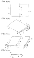
- Fig. 3(a) is the plan of a paper sheet showing the center binding processing in which the staples SP are driven in at the two positions at equal distance from the center along the fold line for two-folding of the paper sheet S
- Fig. 3(b) is a perspective view of the booklet SA which has been subjected to the after-processing of center binding and two-folding
- Fig. 3(c) is a perspective view showing the fully opened state of the booklet SA for which the after-processing has been finished
- Fig. 3(d) is a cross-sectional view of the booklet SA to which the after-processing of center binding and two-folding has been applied.
- b denotes the front end of the paper sheet S
- c denotes the cutting line for truing up the front end.
- the first side (p. 1 and p. 8) of the cover sheet K faces outward
- the second side (p. 2 and p. 7) comes to the rear side of the first side, further to the inside of them, the first side of the paper sheet S, the content of the booklet SA, (p. 3 and p. 6) comes, and further to the inside of them, the second surface of the paper sheet S (p. 4 and p. 5) comes;
- the collating of the booklet composed of 8 pages (p. 1 to p. 8) can be made as shown in the drawings.
- the cover sheet K is placed on the cover sheet placing portion 41, and printing is started, by the control section of the image forming apparatus mainframe A, the above-mentioned image forming process is practiced, the paper sheets S carrying an image are subjected to center binding processing and twofold processing by the paper sheet after-processing apparatus B, and the booklets sA are produced and ejected successively.
- the cover sheet K and the paper sheets S which have already an image formed, for one copy of the booklet under it are stacked on the cover sheet placing portion 41, and the conveying out operation is started, by the control section of the paper sheet after-processing apparatus B, the cover sheet k and the paper sheets S are subjected to center binding processing and twofold processing by the paper sheet after-processing apparatus B, and one copy of the booklet SA is produced and ejected.
- Fig. 4 is a drawing showing the overall structure of the paper sheet cutting apparatus C of this invention.
- the paper sheet cutting apparatus C is composed of the first conveyance means (the paper conveyance means before cutting processing) 100, the second conveyance means (the paper conveyance means after cutting processing) 200, the cutting means 300, and the booklet accommodating means 400.
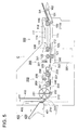
- Fig. 5 is a cross-sectional view showing the paper conveyance paths in the paper sheet cutting apparatus C.
- the booklet SA which has been subjected to twofold processing by the folding means 60 of the paper sheet after-processing apparatus B, is ejected onto the conveyance belt 101 arranged at the entrance portion of the paper sheet cutting apparatus C.
- the conveyance belt 101 is supported in such a way that it is capable of revolution by the supporting member 102, and is made to revolve by the driving roller 103.
- the lower conveyance belt 111 which is entrained around the driving roller 112 and the driven roller 113, is arranged in such a way that it is capable of revolution.
- the upper conveyance belt 114 is arranged in pressing contact with the lower conveyance belt 111 and is driven to revolve.
- the upper conveyance belt which is entrained around the rollers 115 and 116, is supported by the supporting member 117 in such a way that it is capable of revolution.
- the supporting member 117 is urged by the spring 118, and brings the upper conveyance belt 114 into pressing contact with the lower conveyance belt 111.
- the booklet SA which has been conveyed by the conveyance belt 101, is conveyed as pressed and gripped by the lower conveyance belt 111 and the upper conveyance belt 114.
- the driving roller 121 connected to the driving means and the driven roller 122 rotated by the pressing contact with the driving roller 121 are disposed.
- the booklet SA which is conveyed as gripped by the lower conveyance belt 111 and the upper conveyance belt 114, passes the guide plate 123, and is conveyed as gripped by the driving roller 121 and the driven roller 122.
- the cutting means 300 composed of the upper cutting blade 301, lower cutting blade 302, movable plate 310, the pressing roller 311, the trash box 320, and the driving means is arranged.
- the detail of the cutting means 300 will be described later.
- the booklet SA which has been finished, with its front end b cut by the cutting means 300, is conveyed as gripped by the revolving lower conveyance belt 101, the upper conveyance belt 206 being driven to revolve, and the upper roller 205 rotating for driving, in the second conveyance means 200.
- the lower conveyance belt 201 is made to revolve by the driving roller 202 connected to the driving means.
- 203 denotes the driven roller which is driven to rotate by the lower conveyance belt 201.
- the conveyance supporting plate 204 is fixedly provided in the neighborhood of the booklet conveyance path inside the lower conveyance belt 201.
- the upper conveyance belt 206 is entrained around the rollers 207 and 208, is capable of revolution, and is supported by the supporting member 209.
- the supporting member 209 is spring-urged and presses the upper conveyance belt 206 to the conveyance supporting plate 204 through the lower conveyance belt 201.
- the booklet SA which has been subjected to cutting processing, passes the clearance between the lower conveyance belt 201 and the upper roller 205 in the second conveyance means 200, and further, is conveyed as pressed and gripped by the lower conveyance belt 201 and the upper conveyance belt 206.
- the booklet SA which is conveyed in the horizontal direction by the lower conveyance belt 201, is guided by the rotating roller 211 having a large diameter and the fixedly arranged guide plate, is deflected about 90° upward in the vertical direction, and is conveyed upward.
- the booklet SA is further passes the booklet ejecting opening 214 to be ejected as gripped by the large diameter roller 211 and the pinch roller 213, and is placed on the booklet carrying table 401 of the booklet accommodating means 400, with its fold portion positioned above and its front end b positioned below.
- the booklet accommodating means 400 is composed of the booklet carrying table 401, the movable wall member (the pusher) 410, the partition member (the holder) 420, the pressing wall member 430, and the driving means.
- the booklet carrying table 401 receives a plurality of copies of the booklet SA, which have already been cut-processed, from the booklet ejecting opening 214 successively, and carries them with the fold portion positioned above and the paper sheets superposed on one another.
- the movable wall member 410 stands upright on the booklet carrying table 401, is supported in such a way that it is capable of horizontal moving, presses the [paper] cover sheet surface of the booklet SA stacked on the booklet carrying table 401, and moves back and forth in the horizontal direction between on the booklet carrying table 401 and the booklet ejecting opening 214.
- the movable wall member 410 usually supports the booklet SA carried on the booklet carrying table 401 at a stop position that is a little advancing from the booklet ejecting opening 214, and is retracted to a position to make the booklet ejecting opening open every time when the booklet SA having been cut-processed is conveyed to the booklet carrying table 401; after the booklet SA has finished passing the booklet ejecting opening 214, it returns to the stop position as pressing the [paper] cover sheet surface of the booklet SA, and remains on standby.
- the partition member 420 is capable of moving in the vertical direction which is orthogonal to the booklet carrying table 401.
- the partition member 420 supports the cover sheet surface of the booklet SA that has been already carried in place of the movable wall member 410, and in accordance with the operation of the movable wall member to advance to the stop position as pressing the cover sheet surface of the next booklet SA, the partition member 420 starts descending along the rear end portion of the booklet carrying table 401 to retract, to make it possible to receive the next booklet SA on the booklet carrying table 401.
- the partition member 420 starts to move upward.
- the pressing wall member 430 stands upright on the booklet carrying table 401, is supported in a movable manner, and is urged by a spring.
- the booklet touching surface of the pressing wall member 430 is opposite to the movable wall member 410 or the partition member 420, and presses and holds the surface of the cover sheet of the booklet SA carried on the booklet carrying table 410.
- Fig. 6 is a drawing showing the structure of the driving means of the booklet conveyance system.
- the motor M1 for conveying booklets drives the first conveyance means 100 and the second conveyance means 200.
- the gear g1 which is provided on the driving shaft of the motor M1 for conveying a booklet, rotates the driving roller 121 of the first conveyance means 100 through the gears g2, g3, g4, and g5.
- the driving roller 121 rotates the driving roller 112 through the belt TB1, and makes the lower conveyance belt 111 revolve.
- the belt TB2 which is entrained around the pulley TP1 provided on the same shaft as the gear g4, is also entrained around the pulleys TP2, TP3, and TP4, and is capable of revolving.
- the upper roller 205 On the rotary shaft of the pulley TP2, the upper roller 205 is fixed and is able to rotate.
- the driving roller 202 makes the lower conveyance belt 201 revolve.
- the belt TB3 which is entrained around the pulley TP5 fixed on the rotary shaft of the driving roller 202 and the pulley TP6 provided on the intermediate shaft, rotates the large diameter roller 211 fixed on the rotary shaft of the gear g9 through the gears g8 and g9 which are fixed on the rotary shaft of the pulley TP6.
- Fig. 7 is a cross-sectional view showing the driving means for the lower conveyance belt 201 and the movable stopper 221 of the second conveyance means 200.
- the motor M2 for moving the movable stopper moves the movable stopper 221 to the specified position corresponding to the paper size through the gears g11 and g12 and the belt TB4.
- the motor M3 for releasing the stopper drives to rotate the cam 222 through the gears g13 and g14, and makes the movable stopper 221 rise and fall.
- the movable stopper 221 is kept in the initial state of rising when the front end portion of the booklet SA is expected to hit it, and is brought into the state of falling by the driving of the motor M3 when the booklet SA is ejected.
- the control means selects an optimum value on the basis of these numerical set values or the detected thickness of the booklet.
- Fig. 8 is the front view of the driving means for the pressing unit including the upper conveyance belt 206.
- the motor M4 for pressing rotates the rotary disk 231 through the gears g21, g22, g23, g24, g25, and g26.
- the eccentric pin 232 which is planted in the rotary disk 231, is connected to the lower end portion of the crank 233, to oscillate the crank 233.
- the upper end portion of the crank 233 is connected to the coupling plate 234, to move the coupling plate 234 up and down.
- the coupling plate 234 is urged downward in the drawing by the two springs 235.
- the upper end portions of the linking rods 236 are fixed to the pressing member 240.
- the pressing member 240 is spring-urged to the supporting member 209 which supports the upper conveyance belt 206, and is supported in such a way that it is able to move up and down.
- the pressing member 240 moves up and down by the driving rotation of the rotary disk 231 through the crank 233, the coupling plate 234, and the linking rods 236. Further, the pressing member 240 moves in accordance with the thickness of the booklet SA, and presses the upper surface of the booklet SA.
- Fig. 9 is a cross-sectional view of the cutting means 300.
- the cutting means 300 is composed of the upper cutting blade 301, the lower cutting blade 302, and the driving means for driving the upper cutting blade in such a way that it is capable of moving up and down.
- the motor M5 for cutting rotates the gears g31, g32, and g33, and eccentrically rotates the eccentric pin 303 planted at an eccentric position of the gear 33.
- the front end portion of the eccentric pin 303 slides on the inner peripheral surface of the movable member 304, to make the movable member move up and down.
- the upper blade supporting frame member 306 is fixed.
- the upper cutting blade 301 is fixed to the upper blade supporting frame member 306.
- the front end of the booklet SA is cut by the edge of the descending upper cutting blade 301 and the edge of the lower cutting blade at the fixed position.
- 320 denotes the trash box for accommodating the cut waste from the front end.
- the pressing plate 309 is supported by the upper blade supporting frame member 306 as urged by the spring 308. At the bottom of the upper blade supporting frame member 306, the pressing roller 311 for pressing the movable plate 310 is supported.
- the pressing plate 309 descends, to press the upper surface of the booklet SA placed on the lower cutting blade 302, and next, the descending pressing roller 311 presses the movable plate 310, and the edge of the upper cutting blade 301 cuts the front end b.
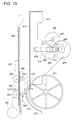
- Fig. 10 is a cross-sectional view showing the movable wall member (hereinafter referred to as the pusher) 410, and the partition member (hereinafter referred to as the holder) 420 in the neighborhood of the booklet ejecting opening 214.
- the pusher 410 comprises the upright vertical wall portion 411 for pressing the carried booklet SA, and is capable of horizontal moving to the direction of the booklet carrying table 401.
- the motor M6 for moving the pusher rotates the rotary disk 412 through the gears g41, g42, g43, g44, and g45.
- the eccentric pin 413 which is planted at the eccentric position of the rotary disk 412, is connected to the right end portion of the crank 414, to oscillate the crank 414.
- the left end portion of the crank 414 shown in the drawing is connected to the pusher 410, to move the pusher 410 in the horizontal direction.
- the pusher 410 as shown by the solid line in the drawing shows that it is located at the retracted position, that is, it is in the state to make the booklet ejecting opening 214 open to enable the passing of the booklet SA.
- the position shown by the single dot and dash line is the stop position to which the pusher 410 is moved horizontally by the driving means.
- the movable holding members 421 which are arranged at the both end portions of the holder 420 arranged parallel to it in the neighborhood of the pusher 410, hold a two pairs of rollers 422 and 423 in such a way to enable their rotation.
- the two pairs of rollers 422 and 423 can move as rolling along the guide rails disposed at the both side end portions of the main body of the apparatus, to make the movable holding member 421 capable of moving up and down.
- the movable holding member 421 is driven to move up and down along the guide rails 424 by the motor M7 for moving the holder up and down and the driving means which are provided below the guide rails.
- the holder 420 as shown in the drawing shows that it has moved upward from the retracting position below and is in the state capable of holding the booklet SA.
- Fig. 11 is a perspective view of the booklet accommodating means 400 composed of the pusher 410, the holder 420, and the pressing wall member 430.
- Fig. 12 is a cross-sectional view showing the booklet accommodating means 400 in the state carrying a plurality of copies of the booklet SA on the booklet carrying table 401.
- the pusher 410 is moved in the horizontal direction shown by the arrow mark by the driving of the motor M6 for moving the pusher.
- the holder 420 is moved in the vertical direction shown by the arrow mark by the motor M7 for moving the holder up and down.
- the pressing wall member 430 is urged by the constant load spring member 431, and is moved in the horizontal direction shown by the arrow mark.
- the pusher 410 After the booklet SA is conveyed out from the booklet ejecting opening 214, and the lower edge portion of the booklet SA passes the gripping position of the large diameter roller 211 and the pinch roller 213, the pusher 410 starts to move forward by the driving of the motor M6 for moving the pusher.
- the pusher 410 moves forward and presses the booklet SA to move it to the direction of the holder 420.
- the holder 420 starts to descend by the start of driving of the motor M7 for moving the holder up and down.
- the lower part of the booklet SA is gripped closely in the upright position by the pusher 410 and the spring-urged pressing wall member 430.
- the upper parts of the booklets SA are supported as overlapping one another in the space extending over the tilted surface portion 432 of the pressing wall member 430. After the completion of the carrying of the booklets, or during the operation of carrying the booklets, it is possible to take out one of the booklets SA easily by holding the upper part of it.
- Fig. 13 is a schematic drawing showing the arrangement of the sensors and the motors in the paper sheet cutting apparatus C.
- PS1 denotes the sensor placed at the entrance portion of the first conveyance means 100
- PS2 denotes the conveyance portion sensor placed in the second conveyance means 200
- PS3 denotes the ejection portion sensor placed at the exit portion of the second conveyance means 200.
- Fig. 14 is the plan showing the basic screen of the operation panel of the image forming apparatus mainframe A. On this operation panel, if the paper sheet size, the number of sheets to set, etc. are set and further the output mode is set, the apparatus enters in the paper sheet after-processing mode shown in Fig. 15.
- Fig. 15 is the plan showing the screen of the operation panel in the case where paper sheet after-processing mode is set. In this screen, by selecting center binding, center folding, and cutting, and setting them by the OK key, the finisher adjustment menu screen appears as shown in Fig. 16.
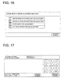
- Fig. 16 is the plan of the operation panel showing the finisher adjustment menu screen.
- Fig. 17 is the plan of the operation panel showing the cutting stopper position adjustment screen. In this screen, the amount of position adjustment is inputted by the numerical keys and it is settled by the setting key.
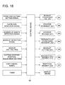
- Fig. 18 is a block diagram showing the control of the paper sheet cutting apparatus C
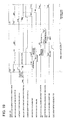
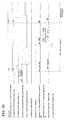
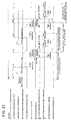
- Fig. 19 is the time chart in the case of practicing the cutting processing. In the following, the operation of each driving means by the control means 90 will be explained.
- the driving of the motor M1 for conveying a booklet is stopped, while the driving of the motor M3 for releasing the movable stopper and the motor M7 for moving the holder up and down is started. After that, by the related operation of the motor M6 for moving the pusher and the motor M7 for moving the holder up and down, the booklet SA is accommodated in the booklet accommodating means 400.
Landscapes
- Life Sciences & Earth Sciences (AREA)
- Forests & Forestry (AREA)
- Engineering & Computer Science (AREA)
- Mechanical Engineering (AREA)
- Physics & Mathematics (AREA)
- General Physics & Mathematics (AREA)
- Folding Of Thin Sheet-Like Materials, Special Discharging Devices, And Others (AREA)
- Control Or Security For Electrophotography (AREA)
Abstract
Description
passes the gripping position of the
Claims (10)
- A sheet cutting apparatus for cutting a front end portion opposite to a folded portion of a booklet finished by a center folding processing, comprising:a first driving source to drive a conveying device for conveying said booklet;a second driving source to drive a movable stopping device for stopping said booklet at a predetermined position;a third driving source to drive a pressing device for pressing said booklet;a fourth driving source to drive a cutting device for cutting said front end portion of said booklet;a fifth driving source to drive a booklet accommodating device for accommodating said booklet processed by said cutting device; anda controlling section to control each of said first driving source, said second driving source, said third driving source, said fourth driving source and said fifth driving source;wherein said controlling section deactivates all of said first driving source, said second driving source, said third driving source and said fifth driving source, when said controlling section activates said fourth driving source.
- A sheet cutting apparatus for cutting a front end portion opposite to a folded portion of a booklet finished by a center folding processing, comprising:a conveying device for conveying said booklet;a stopping device for stopping said booklet at a predetermined position;a cutting device for cutting said front end portion of said booklet; anda controlling section to control each of said conveying device, said stopping device and said cutting device;wherein said controlling section controls said stopping device so as to variably determine a stopping position of said booklet stopped by said stopping device, based on a number of sheets included in said booklet conveyed to said cutting device by said conveying device.
- A sheet cutting apparatus for cutting a front end portion opposite to a folded portion of a booklet finished by a center folding processing, comprising:a conveying device for conveying said booklet;a stopping device for stopping said booklet at a predetermined position;a cutting device for cutting said front end portion of said booklet; anda controlling section to control each of said conveying device, said stopping device and said cutting device;wherein said controlling section automatically determines that a cutting processing of cutting said front end portion of said booklet is not performed, when a number of sheets included in said booklet is set at a number lower than a predetermined number of sheets.
- The sheet cutting apparatus of claim 3,
wherein said controlling section automatically performs controlling actions so as not to perform said cutting processing and to inform a fact that said cutting processing is not performed, when a number of sheets included in said booklet is set at a number lower than a predetermined number of sheets. - A sheet cutting apparatus for cutting a front end portion opposite to a folded portion of a booklet finished by a center folding processing, comprising:a conveying device for conveying said booklet;a stopping device for stopping said booklet at a predetermined position;a cutting device for cutting said front end portion of said booklet;a booklet accommodating device for accommodating said booklet processed by said cutting device; anda controlling section to control each of said conveying device, said stopping device, said cutting device and said booklet accommodating device;wherein, when an execution of a cutting processing operation is selected, said controlling section controls said conveying device so as to convey said booklet processed by said cutting device to said booklet accommodating device, and, when a non-execution of said cutting processing operation is selected, said controlling section controls said conveying device so as to convey said booklet to said booklet accommodating device without performing said cutting processing operation.
- A sheet cutting apparatus for cutting a front end portion opposite to a folded portion of a booklet finished by a center folding processing, comprising:a conveying device for conveying said booklet;a stopping device for stopping said booklet at a predetermined position;a cutting device for cutting said front end portion of said booklet;a booklet accommodating device for accommodating said booklet processed by said cutting device; anda controlling section to control each of said conveying device, said stopping device, said cutting device and said booklet accommodating device;wherein, when a further execution of an image-forming operation is cancelled in a mid-course of conducting said image-forming operation, said controlling section controls said conveying device so as to convey said booklet to said booklet accommodating device without performing a cutting processing operation by said cutting device.
- A sheet cutting apparatus for cutting a front end portion opposite to a folded portion of a booklet finished by a center folding processing, comprising:a conveying device for conveying said booklet;a stopping device for stopping said booklet at a predetermined position;a cutting device for cutting said front end portion of said booklet;a booklet accommodating device for accommodating said booklet processed by said cutting device; anda controlling section to control each of said conveying device, said stopping device, said cutting device and said booklet accommodating device;wherein said controlling section applies a magnetizing processing to a driving source for driving said stopping device to keep said stopping device in a fixed state, just before a leading edge portion of said booklet, being conveyed by said conveying device, is batted against a stopping member of said stopping device.
- A sheet cutting apparatus for cutting a front end portion opposite to a folded portion of a booklet finished by a center folding processing, comprising:a conveying device for conveying said booklet;a stopping device for stopping said booklet at a predetermined position;a cutting device for cutting said front end portion of said booklet;a booklet accommodating device for accommodating said booklet processed by said cutting device; anda controlling section to control each of said conveying device, said stopping device, said cutting device and said booklet accommodating device;wherein said controlling section controls said conveying device so as to simultaneously conduct a conveyance processing of said booklet processed by said cutting device and a feed-in processing of a succeeding booklet, by conveying said succeeding booklet into said cutting device while conveying said booklet processed by said cutting device to said booklet accommodating device.
- A sheet cutting apparatus for cutting a front end portion opposite to a folded portion of a booklet finished by a center folding processing, comprising:a conveying device for conveying said booklet;a stopping device for stopping said booklet at a predetermined position;a cutting device for cutting said front end portion of said booklet;a booklet accommodating device for accommodating said booklet processed by said cutting device; anda controlling section to control each of said conveying device, said stopping device, said cutting device and said booklet accommodating device;wherein said controlling section adjusts a stopping position of a stopping member of said stopping device corresponding to cutting size set arbitrarily.
- An image-forming apparatus, comprising:an image-forming section to form an image on a sheet, fed from a sheet feeding device, based on image information;a sheet finishing section, which comprises a binding processor to apply a binding processing to a set of sheets, each of which is said sheet having said image formed by said image-forming section, and a folding processor to apply a processing to said set of sheets processed by said binding processor; andthe sheet cutting apparatus cited in any one ofclaims 1 - 9; pparatus produces a bookletwherein said image-forming apparatus produces a booklet by applying said binding processing and said folding processing to said set of sheets, and said cutting device cuts said front end portion of said booklet.
Priority Applications (1)
| Application Number | Priority Date | Filing Date | Title |
|---|---|---|---|
| EP05109307A EP1634682B1 (en) | 2000-06-26 | 2001-06-21 | Paper cutting apparatus and image forming apparatus with such a paper cutting apparatus |
Applications Claiming Priority (2)
| Application Number | Priority Date | Filing Date | Title |
|---|---|---|---|
| JP2000191060 | 2000-06-26 | ||
| JP2000191060A JP2002003069A (en) | 2000-06-26 | 2000-06-26 | Paper cutting device and image forming device |
Related Child Applications (1)
| Application Number | Title | Priority Date | Filing Date |
|---|---|---|---|
| EP05109307A Division EP1634682B1 (en) | 2000-06-26 | 2001-06-21 | Paper cutting apparatus and image forming apparatus with such a paper cutting apparatus |
Publications (3)
| Publication Number | Publication Date |
|---|---|
| EP1166976A2 true EP1166976A2 (en) | 2002-01-02 |
| EP1166976A3 EP1166976A3 (en) | 2004-01-28 |
| EP1166976B1 EP1166976B1 (en) | 2006-08-02 |
Family
ID=18690419
Family Applications (2)
| Application Number | Title | Priority Date | Filing Date |
|---|---|---|---|
| EP05109307A Expired - Lifetime EP1634682B1 (en) | 2000-06-26 | 2001-06-21 | Paper cutting apparatus and image forming apparatus with such a paper cutting apparatus |
| EP01115098A Expired - Lifetime EP1166976B1 (en) | 2000-06-26 | 2001-06-21 | Paper cutting apparatus and image forming apparatus with such a paper cutting apparatus |
Family Applications Before (1)
| Application Number | Title | Priority Date | Filing Date |
|---|---|---|---|
| EP05109307A Expired - Lifetime EP1634682B1 (en) | 2000-06-26 | 2001-06-21 | Paper cutting apparatus and image forming apparatus with such a paper cutting apparatus |
Country Status (4)
| Country | Link |
|---|---|
| US (1) | US6532856B2 (en) |
| EP (2) | EP1634682B1 (en) |
| JP (1) | JP2002003069A (en) |
| DE (2) | DE60132388T2 (en) |
Families Citing this family (31)
| Publication number | Priority date | Publication date | Assignee | Title |
|---|---|---|---|---|
| US7137625B2 (en) * | 2002-02-12 | 2006-11-21 | Ricoh Company, Ltd. | Sheet finisher including means for setting cutting position image forming system including the sheet finisher |
| US6929256B2 (en) * | 2002-09-03 | 2005-08-16 | Konica Corporation | Post processing device with saddle stitching |
| JP2004195569A (en) * | 2002-12-17 | 2004-07-15 | Fuji Xerox Co Ltd | Paper processing system and cutter unit |
| US7207557B2 (en) * | 2003-06-04 | 2007-04-24 | Konica Minolta Business Technologies, Inc. | Image forming system and single-sheet processing machine |
| US7255337B2 (en) * | 2003-10-01 | 2007-08-14 | Konica Minolta Business Technologies, Inc. | Oscillating transport unit for post-processing device |
| JP2005306559A (en) * | 2003-10-01 | 2005-11-04 | Konica Minolta Business Technologies Inc | Paper post-treatment device |
| JP4289456B2 (en) * | 2003-11-12 | 2009-07-01 | 株式会社デュプロ | Bookbinding apparatus and bookbinding pretreatment apparatus |
| WO2006004217A1 (en) | 2004-07-05 | 2006-01-12 | Japan Science And Technology Agency | Probe for nitrogen monoxide detection/quantitative determination, and method of nitrogen monoxide detection/quantitative determination using the same |
| JP2006088289A (en) * | 2004-09-27 | 2006-04-06 | Konica Minolta Business Technologies Inc | Paper cutter, paper post-processing device and image forming system |
| JP2006110664A (en) * | 2004-10-14 | 2006-04-27 | Konica Minolta Business Technologies Inc | Paper cutting device, paper post-processing device, and image forming system |
| JP4402027B2 (en) * | 2005-08-30 | 2010-01-20 | キヤノン株式会社 | Image forming apparatus, sheet processing apparatus, and control method for sheet processing apparatus |
| JP2007326348A (en) * | 2006-06-09 | 2007-12-20 | Canon Inc | Image forming bookbinding system |
| DE202006017275U1 (en) * | 2006-11-02 | 2008-03-27 | Michael Hörauf Maschinenfabrik GmbH & Co. KG | Apparatus for obtaining a flat blank with a reference |
| JP4921192B2 (en) * | 2007-01-31 | 2012-04-25 | キヤノン株式会社 | Sheet cutting apparatus and image forming apparatus |
| US8616106B2 (en) * | 2007-02-27 | 2013-12-31 | Canon Kabushiki Kaisha | Sheet cutting apparatus and image forming apparatus |
| US8894064B2 (en) * | 2008-01-31 | 2014-11-25 | Hewlett-Packard Development Company, L.P. | Inkjet printer accessory |
| US20090193948A1 (en) * | 2008-01-31 | 2009-08-06 | Eric Munro Innes | Sheet Cutter Assembly |
| JP5328236B2 (en) * | 2008-06-23 | 2013-10-30 | キヤノン株式会社 | Sheet processing system, control method and program for sheet processing system |
| JP4823347B2 (en) * | 2009-10-02 | 2011-11-24 | キヤノンファインテック株式会社 | Sheet processing apparatus and image forming apparatus |
| JP5762036B2 (en) * | 2011-02-14 | 2015-08-12 | キヤノン株式会社 | Recording medium cutting device |
| JP5967896B2 (en) * | 2011-10-21 | 2016-08-10 | キヤノン株式会社 | Sheet cutting device and printer |
| CN102935956B (en) * | 2012-11-23 | 2015-03-11 | 北塘区军之印纸品加工厂 | Post-it cutting system |
| CN104309143B (en) * | 2014-08-07 | 2016-09-14 | 山东金宇实业股份有限公司 | Film automatic cutting method, system and controller |
| US10300716B2 (en) * | 2015-02-19 | 2019-05-28 | Custom S.P.A. | Printing apparatus with stacking position for output |
| JP2017213643A (en) * | 2016-05-31 | 2017-12-07 | キヤノン株式会社 | Cutting device and image formation device |
| JP6768352B2 (en) | 2016-05-31 | 2020-10-14 | キヤノン株式会社 | Sheet cutting device |
| JP6926924B2 (en) * | 2017-10-16 | 2021-08-25 | 富士フイルムビジネスイノベーション株式会社 | Image processing device and image processing method |
| CN110271044B (en) * | 2019-07-26 | 2020-11-17 | 安徽科技学院 | Fresh corn positioning and spike cutting device |
| CN112497289B (en) * | 2020-11-23 | 2022-07-12 | 河北金博士卫生用品有限公司 | Coiled tissue equidistant center hole cutting and conveying equipment |
| CN112588651B (en) * | 2020-11-26 | 2022-04-22 | 金乡县圣亚达铅笔有限公司 | Clamping and conveying equipment for pencil lead processing |
| CN113414809B (en) * | 2021-06-21 | 2022-10-14 | 安徽科技学院 | Automatic fresh corn cropping device and control method |
Family Cites Families (29)
| Publication number | Priority date | Publication date | Assignee | Title |
|---|---|---|---|---|
| US3733947A (en) * | 1968-06-18 | 1973-05-22 | Harris Intertype Corp | Book trimming machine |
| US3570344A (en) * | 1968-06-18 | 1971-03-16 | Harris Intertype Corp | Apparatus and method for trimming books |
| DE2554662A1 (en) * | 1975-12-05 | 1977-06-23 | Koenig & Bauer Ag | PROCESS AND DEVICE FOR IMMEDIATE TRIMMING OF FOLDED SIGNATURES PRODUCED IN ROLLER ROTARY PRINTING MACHINES |
| DE2536558C2 (en) * | 1975-08-16 | 1984-07-05 | Maschinenbau Oppenweiler Gmbh, 7155 Oppenweiler | Device for cutting through a stack of sheets with a circular knife |
| DE3101911A1 (en) * | 1981-01-22 | 1982-09-02 | Karl Mohr | "DEVICE FOR CUTTING PAPER, CARDBOARD OR THE LIKE .." |
| DE3302946C2 (en) * | 1982-02-05 | 1986-12-04 | H. Wohlenberg KG GmbH & Co, 3000 Hannover | Three-knife cutting machine |
| DE3613316C1 (en) * | 1986-04-19 | 1988-02-18 | Wolfgang Mohr | Device for cutting stacked, sheet-like material |
| US5086681A (en) * | 1989-12-29 | 1992-02-11 | K. S. Macey Machine Company, Inc. | Book feeding and trimming apparatus |
| DE4002102A1 (en) * | 1990-01-25 | 1991-08-08 | Wolfgang Mohr | DEVICE FOR CUTTING STACKED, SHEET-SHAPED GOODS WITH A FRONT PUSHER TO ALIGN THE GOODS WITH A FEED UNIT |
| US5199341A (en) * | 1990-05-10 | 1993-04-06 | Numerical Concepts, Inc. | In-line, adjustable gap cutting sheeter for printed webs |
| WO1992002888A1 (en) * | 1990-07-27 | 1992-02-20 | Ross Harvey M | System and method of manufacturing a single book copy |
| US5159395A (en) * | 1991-08-29 | 1992-10-27 | Xerox Corporation | Method of scheduling copy sheets in a dual mode duplex printing system |
| DE4141767A1 (en) * | 1991-12-18 | 1993-06-24 | Will E C H Gmbh & Co | METHOD AND ARRANGEMENT FOR PRODUCING BOOKS AND BROCHURES |
| US5146824A (en) * | 1992-01-29 | 1992-09-15 | Lajoie J Andre | Auxiliary punching device for punching machine |
| JP3372573B2 (en) | 1992-07-01 | 2003-02-04 | 株式会社リコー | Recording device |
| DE9209633U1 (en) * | 1992-07-17 | 1992-12-17 | Stahl Gmbh & Co Maschinenfabrik, 7140 Ludwigsburg | Cutting device |
| US5377569A (en) * | 1993-05-07 | 1995-01-03 | Xerox Corporation | Signature booklet maker with a modified fold blade and a trim waste elimination device |
| US5461469A (en) * | 1993-12-20 | 1995-10-24 | Xerox Corporation | Method of setting-up a finishing apparatus |
| JPH07187479A (en) | 1993-12-28 | 1995-07-25 | Fuji Xerox Co Ltd | Sheet processing device |
| EP0686463B1 (en) * | 1994-06-08 | 1999-09-29 | Ferag AG | Apparatus for cutting printed products, like newspapers, magazines, brochures, on at least two sides |
| CH689449A5 (en) * | 1994-08-12 | 1999-04-30 | Grapha Holding Ag | Cutting process for flat print products along preset cutting line |
| US5694823A (en) * | 1994-10-18 | 1997-12-09 | The Challenge Machinery Company | Document trimming apparatus |
| JPH08192951A (en) | 1995-01-13 | 1996-07-30 | Fuji Xerox Co Ltd | Sheet post-treating device of image forming device |
| FR2739846B1 (en) * | 1995-10-12 | 1997-12-19 | C P Bourg Sa | BOOKLET FINISHING MACHINE |
| JPH10148983A (en) | 1996-11-20 | 1998-06-02 | Minolta Co Ltd | Paper processor |
| JP3625347B2 (en) | 1996-12-13 | 2005-03-02 | キヤノンファインテック株式会社 | Sheet processing apparatus and image forming apparatus |
| US6134999A (en) * | 1997-08-15 | 2000-10-24 | Heidelberg Druckmaschinen Ag | Trimming device for flat articles |
| US6193458B1 (en) * | 1999-04-29 | 2001-02-27 | Jeffrey D. Marsh | System for and method of binding and trimming a perfect bound book |
| EP1129972B1 (en) * | 2000-02-29 | 2005-07-20 | Konica Corporation | Sheet cutting device and image forming apparatus equipped therewith |
-
2000
- 2000-06-26 JP JP2000191060A patent/JP2002003069A/en active Pending
-
2001
- 2001-06-20 US US09/885,401 patent/US6532856B2/en not_active Expired - Lifetime
- 2001-06-21 DE DE60132388T patent/DE60132388T2/en not_active Expired - Lifetime
- 2001-06-21 EP EP05109307A patent/EP1634682B1/en not_active Expired - Lifetime
- 2001-06-21 EP EP01115098A patent/EP1166976B1/en not_active Expired - Lifetime
- 2001-06-21 DE DE60121866T patent/DE60121866T2/en not_active Expired - Lifetime
Also Published As
| Publication number | Publication date |
|---|---|
| DE60121866T2 (en) | 2007-07-26 |
| DE60132388T2 (en) | 2008-12-24 |
| EP1634682A3 (en) | 2006-03-22 |
| DE60121866D1 (en) | 2006-09-14 |
| EP1166976B1 (en) | 2006-08-02 |
| EP1634682B1 (en) | 2008-01-09 |
| DE60132388D1 (en) | 2008-02-21 |
| EP1166976A3 (en) | 2004-01-28 |
| US6532856B2 (en) | 2003-03-18 |
| JP2002003069A (en) | 2002-01-09 |
| US20010054342A1 (en) | 2001-12-27 |
| EP1634682A2 (en) | 2006-03-15 |
Similar Documents
| Publication | Publication Date | Title |
|---|---|---|
| EP1634682B1 (en) | Paper cutting apparatus and image forming apparatus with such a paper cutting apparatus | |
| JP6360285B2 (en) | Sheet processing apparatus and image forming system provided with the same | |
| KR100262915B1 (en) | Paper finishing device | |
| JP6274768B2 (en) | Sheet bundle binding processing apparatus and image forming system provided with the same | |
| JP6130751B2 (en) | Sheet conveying apparatus and image forming system provided with the same | |
| JP2003054832A (en) | Paper sheet post-processing method, paper sheet post- processing apparatus and image forming apparatus | |
| JP3832126B2 (en) | Image forming system | |
| JP3777902B2 (en) | Post-processing apparatus and image forming system | |
| JP4203788B2 (en) | Sheet processing apparatus and image forming apparatus having the same | |
| JP3765226B2 (en) | Image forming apparatus provided with sheet post-processing device | |
| JPH0891686A (en) | Paper sheet post-processing device and control system therefor | |
| JP4196905B2 (en) | Paper cutting apparatus and image forming apparatus | |
| JP2001146363A (en) | Paper sheet postprocessing device and image forming device | |
| JP2001206626A (en) | Sheet post-treatment unit and image forming apparatus | |
| JP3918459B2 (en) | Paper post-processing method, paper post-processing apparatus, and image forming apparatus | |
| JP2000211805A (en) | Post-processing device and image forming system | |
| JP2006206333A (en) | Paper cutting device and image forming device | |
| JP4488175B2 (en) | Image forming apparatus | |
| JP6335355B2 (en) | Sheet binding processing apparatus and image forming system using the same | |
| JP2004351566A (en) | Edge cutting device and image forming system | |
| JP4107005B2 (en) | Paper post-processing method, paper post-processing apparatus, and image forming system | |
| JP2003020154A (en) | Paper post-processing device and image forming apparatus | |
| JP2006247836A (en) | Paper cutting device and image forming device | |
| JP3740302B2 (en) | Sheet processing apparatus and image forming apparatus having the same | |
| JP3918458B2 (en) | Paper post-processing method, paper post-processing apparatus, and image forming apparatus |
Legal Events
| Date | Code | Title | Description |
|---|---|---|---|
| PUAI | Public reference made under article 153(3) epc to a published international application that has entered the european phase |
Free format text: ORIGINAL CODE: 0009012 |
|
| AK | Designated contracting states |
Kind code of ref document: A2 Designated state(s): AT BE CH CY DE DK ES FI FR GB GR IE IT LI LU MC NL PT SE TR |
|
| AX | Request for extension of the european patent |
Free format text: AL;LT;LV;MK;RO;SI |
|
| PUAL | Search report despatched |
Free format text: ORIGINAL CODE: 0009013 |
|
| AK | Designated contracting states |
Kind code of ref document: A3 Designated state(s): AT BE CH CY DE DK ES FI FR GB GR IE IT LI LU MC NL PT SE TR |
|
| AX | Request for extension of the european patent |
Extension state: AL LT LV MK RO SI |
|
| 17P | Request for examination filed |
Effective date: 20040727 |
|
| AKX | Designation fees paid |
Designated state(s): DE FR GB |
|
| 17Q | First examination report despatched |
Effective date: 20050610 |
|
| GRAP | Despatch of communication of intention to grant a patent |
Free format text: ORIGINAL CODE: EPIDOSNIGR1 |
|
| GRAS | Grant fee paid |
Free format text: ORIGINAL CODE: EPIDOSNIGR3 |
|
| GRAA | (expected) grant |
Free format text: ORIGINAL CODE: 0009210 |
|
| AK | Designated contracting states |
Kind code of ref document: B1 Designated state(s): DE FR GB |
|
| REG | Reference to a national code |
Ref country code: GB Ref legal event code: FG4D |
|
| REF | Corresponds to: |
Ref document number: 60121866 Country of ref document: DE Date of ref document: 20060914 Kind code of ref document: P |
|
| EN | Fr: translation not filed | ||
| PLBE | No opposition filed within time limit |
Free format text: ORIGINAL CODE: 0009261 |
|
| STAA | Information on the status of an ep patent application or granted ep patent |
Free format text: STATUS: NO OPPOSITION FILED WITHIN TIME LIMIT |
|
| 26N | No opposition filed |
Effective date: 20070503 |
|
| PG25 | Lapsed in a contracting state [announced via postgrant information from national office to epo] |
Ref country code: FR Free format text: LAPSE BECAUSE OF FAILURE TO SUBMIT A TRANSLATION OF THE DESCRIPTION OR TO PAY THE FEE WITHIN THE PRESCRIBED TIME-LIMIT Effective date: 20070511 |
|
| PG25 | Lapsed in a contracting state [announced via postgrant information from national office to epo] |
Ref country code: FR Free format text: LAPSE BECAUSE OF FAILURE TO SUBMIT A TRANSLATION OF THE DESCRIPTION OR TO PAY THE FEE WITHIN THE PRESCRIBED TIME-LIMIT Effective date: 20060802 |
|
| PGFP | Annual fee paid to national office [announced via postgrant information from national office to epo] |
Ref country code: GB Payment date: 20170621 Year of fee payment: 17 Ref country code: DE Payment date: 20170613 Year of fee payment: 17 |
|
| REG | Reference to a national code |
Ref country code: DE Ref legal event code: R119 Ref document number: 60121866 Country of ref document: DE |
|
| GBPC | Gb: european patent ceased through non-payment of renewal fee |
Effective date: 20180621 |
|
| PG25 | Lapsed in a contracting state [announced via postgrant information from national office to epo] |
Ref country code: GB Free format text: LAPSE BECAUSE OF NON-PAYMENT OF DUE FEES Effective date: 20180621 Ref country code: DE Free format text: LAPSE BECAUSE OF NON-PAYMENT OF DUE FEES Effective date: 20190101 |