EP1166909A1 - Method and apparatus for the making of branched pipes - Google Patents
Method and apparatus for the making of branched pipes Download PDFInfo
- Publication number
- EP1166909A1 EP1166909A1 EP01250246A EP01250246A EP1166909A1 EP 1166909 A1 EP1166909 A1 EP 1166909A1 EP 01250246 A EP01250246 A EP 01250246A EP 01250246 A EP01250246 A EP 01250246A EP 1166909 A1 EP1166909 A1 EP 1166909A1
- Authority
- EP
- European Patent Office
- Prior art keywords
- tool
- opening
- necking
- edge
- workpiece
- Prior art date
- Legal status (The legal status is an assumption and is not a legal conclusion. Google has not performed a legal analysis and makes no representation as to the accuracy of the status listed.)
- Granted
Links
Images

Classifications
-
- B—PERFORMING OPERATIONS; TRANSPORTING
- B21—MECHANICAL METAL-WORKING WITHOUT ESSENTIALLY REMOVING MATERIAL; PUNCHING METAL
- B21C—MANUFACTURE OF METAL SHEETS, WIRE, RODS, TUBES OR PROFILES, OTHERWISE THAN BY ROLLING; AUXILIARY OPERATIONS USED IN CONNECTION WITH METAL-WORKING WITHOUT ESSENTIALLY REMOVING MATERIAL
- B21C37/00—Manufacture of metal sheets, bars, wire, tubes or like semi-manufactured products, not otherwise provided for; Manufacture of tubes of special shape
- B21C37/06—Manufacture of metal sheets, bars, wire, tubes or like semi-manufactured products, not otherwise provided for; Manufacture of tubes of special shape of tubes or metal hoses; Combined procedures for making tubes, e.g. for making multi-wall tubes
- B21C37/15—Making tubes of special shape; Making tube fittings
- B21C37/28—Making tube fittings for connecting pipes, e.g. U-pieces
- B21C37/29—Making branched pieces, e.g. T-pieces
- B21C37/298—Forming collars by flow-drilling
Abstract
Description
Für unterschiedliche Einsatzzwecke ist es erforderlich, an zylindrischen Rohren Rohrabgänge bzw. -ansätze zu erzeugen. Beispielsweise ist dies bei der Herstellung t-förmiger Fittings der Fall. Eine Möglichkeit zur Herstellung solcher t-förmiger Fittings besteht darin, in die Mantelfläche des Rohrstücks einen v-förmigen Schnitt einzubringen und hieran ein entsprechend geformtes rohrförmiges Ansatzstück durch Schweißen oder Hartlöten anzusetzen. Diese Vorgehensweise hat jedoch den Nachteil, dass die durch Hartlöten oder Schweißen zu erzeugende Verbindungsnaht aufgrund der V-Form relativ schwierig in einer hinreichend guten Qualität herzustellen ist. Daher sind bereits unterschiedliche Verfahren bekannt geworden, Rohrabgänge durch das Aushalsen einer in die Mantelfläche eingebrachten Bohrung herzustellen. Das Aushalsen erfolgt dabei entweder mittels eines in besonderer Weise profilierten bohrer- bzw. dornähnlichen Werkzeugs oder mittels in spezieller Weise unterhalb des Randes der Bohrung aufspreizbarer Werkzeuge.For different purposes it is necessary to use pipe exits on cylindrical pipes to generate or approaches. For example, this is more T-shaped during manufacture Fittings the case. There is a possibility of producing such t-shaped fittings in making a v-shaped cut in the lateral surface of the pipe section and followed by a correspondingly shaped tubular extension by welding or To start brazing. However, this procedure has the disadvantage that the Brazing or welding seam to be produced relatively due to the V-shape difficult to produce in a sufficiently good quality. Therefore, are already different Processes have become known through the necking of a pipe into the To produce the outer surface of the bore. The necking is done either by means of a specially profiled drill or mandrel-like tool or by means of tools which can be expanded in a special way below the edge of the bore.
Bei der erstgenannten Gruppe von Werkzeugen wird das Werkzeug unter Ausführung einer Rotationsbewegung in die Bohrung eingebracht und bördelt dabei oder beim Wiederherausbewegen aufgrund seiner speziellen Profilierung den Rand der Bohrung auf, indem es Material nach außen zieht. Ein Beispiel für ein in dieser Weise gestaltetes Werkzeug ist durch die DE 32 38 978 A1 gegeben. In der Schrift wird ein spezieller Dorn beschrieben, welcher an seinem Ende ein flaches Formgebungsteil besitzt. Mittels des schnell drehenden Werkzeugs wird in dem mit dem Rohrabgang zu versehenden Rohrstück ein Rundloch erzeugt, dessen Rand dann durch die an dem Formgebungsteil ausgebildeten Bearbeitungskanten unter Bildung eines Kragens aufgebördelt wird.In the former group of tools, the tool is under execution introduced into the bore in a rotational movement and flanges in the process Moving out due to its special profile the edge of the hole, by pulling material outwards. An example of one designed in this way Tool is given by DE 32 38 978 A1. There is a special thorn in the script described, which has a flat shaping part at its end. By means of the fast rotating tool is in the pipe section to be provided with the pipe outlet creates a round hole, the edge of which then through the on the molding trained processing edges is flared to form a collar.
Eine andere Lösung ist durch die DE 31 02 105 A1 bekannt geworden. Hier erfolgt das sogenannte Ausziehen des Materials zur Schaffung eines etwa zylinderförmigen Rohrabgangs dadurch, dass das verwendete Werkzeug aufgrund seiner speziellen konstruktiven Gestaltung zum Ausbördeln aufspreizbar bzw. in seinem Durchmesser veränderbar ist. An dem bohrerähnlichen Werkzeug sind dazu in der Schrift als Formglieder bezeichnete und als Bördeleinrichtung wirkende Stifte oder Finger ausfahrbar bzw. ausklappbar. Diese werden nach dem Durchbohren einer Rohrwand oder einer planen Platte aus dem zunächst als Bohrer fungierenden Werkzeug herausgeschoben und ziehen aufgrund der Rotation des Werkzeugs beim Zurückziehen aus der Bohrung das Material in annähernd zylinderförmigen Querschnitt aus der mit der Bohrung versehenen Wand oder Platte heraus.Another solution has become known from DE 31 02 105 A1. This is done here so-called pulling out of the material to create an approximately cylindrical tube outlet in that the tool used due to its special constructive design for flaring spreadable or in its diameter is changeable. On the drill-like tool are in the script as Shaped pins and extendable pins or fingers acting as a crimping device or fold out. These are after drilling a pipe wall or a flat plate is pushed out of the tool that initially functions as a drill and pull out of the hole due to the rotation of the tool the material in an approximately cylindrical cross-section from the one provided with the bore Wall or plate out.
Die beschriebenen Lösungen sind insbesondere bei der Bearbeitung weicher Materialien wie Kupfer relativ problemlos anzuwenden. Bei harten Materialien wie Stahl unterliegen die Werkzeuge jedoch einer sehr starken Beanspruchung. Dadurch ergibt sich bei der Bearbeitung von Stahl eine relativ geringe Standzeit für die aufgrund ihrer komplizierten Profilierung bzw. Konstruktion ohnehin recht teuren Werkzeuge. Bei den in der Art einer Zange aufspreizbaren oder mit ausfahr- oder ausklappbaren Bolzen ausgestatteten Werkzeugen ergeben sich zusätzliche, konstruktiv bedingte Probleme bei der Erzeugung von Aushalsungen kleinen Querschnitts. Rohrabgänge mit Durchmessern von 11 mm oder weniger lassen sich mit derartigen Werkzeugen zumindest bei Stahlrohren in der Regel nicht herstellen.The solutions described are particularly useful when processing soft materials like copper relatively easy to use. With hard materials like steel the tools, however, are subjected to very high loads. This results in the Machining steel has a relatively short life due to its complicated nature Profiling or construction of tools that are quite expensive anyway. In the kind of a Pliers expandable or equipped with extendable or foldable bolts Tools result in additional, design-related problems during production of small cross-sections. Pipe outlets with a diameter of 11 mm or less can be used with such tools, at least for steel pipes in the Do not make rule.
Auch die EP 0 752 289 beschreibt ein spezielles Aushalsungswerkzeug. Das in der Schrift vorgeschlagene Werkzeug weist zumindest zwei an seinem Umfang ausfahrbare Rollen auf, welche gegen den Rand der Bohrung gedrückt, diesen beim Zurückziehung des Werkzeugs unter Ausbildung eines Kragens aufbördeln. Bei der Schilderung des Standes der Technik wird in der letztgenannten Schrift auch eine Lösung als bekannt angesehen, bei welcher ein zylinderförmiges, sich schnell drehendes Werkzeug in der auszuhalsenden Bohrung eine Pendelbewegung ausführt. Beim Schwingen gegen den Rand der Bohrung übt das Werkzeug jeweils einen gewissen Druck gegen den Rand aus und zieht dabei während des Zurückziehens aus der Bohrung Material aus dieser heraus. Nachteilig ist es hierbei, dass mit der geschilderten Vorgehensweise ausschließlich kegelförmige Rohrabgänge erzeugt werden können, bei denen sich außerdem am Fußpunkt des so entstehenden Kegels eine gewisse Materialschwächung einstellen kann. Durch die Pendelbewegung wird das getriebene Werkzeug ebenfalls verhältnismäßig stark beansprucht.EP 0 752 289 also describes a special necking tool. That in Scripture The proposed tool has at least two rollers that can be extended on its circumference on, which pressed against the edge of the hole, this when retracting the Flare the tool to form a collar. When describing the stand a solution is also known to the technology in the last-mentioned document, in which a cylindrical, rapidly rotating tool in the neck Bore performs a pendulum motion. When swinging against the edge of the hole the tool exerts a certain pressure against the edge and pulls in the process while pulling material out of the hole. It is a disadvantage here that with the described procedure only conical pipe outlets can be generated, which are also at the base of the so emerging cone can set a certain material weakening. Through the Pendulum movement, the driven tool is also relatively strong claimed.
Aus der US 656,425 ist es bekannt, einen vorgeformten, sich konisch nach Außen verjüngenden Abgang mittels eines rotierenden und um die Rotationsachse verschwenkbaren Werkzeugs in eine zylindrische Form zu überführen. Die Schrift lässt offen, auf welche Weise der zunächst konisch verlaufende Abgang zuvor erzeugt wurde. Zum Erhalt der zylindrischen Form für den Rohrabgang werden dessen zunächst an ihren Enden aufeinander zulaufenden Wandungen mittels des dornartigen an seiner Spitze konisch ausgebildeten Werkzeugs quasi auseinander gedrückt. Die hierbei entstehende Gleitreibung zwischen dem angetriebenen Werkzeug und dem Werkstück führt, ebenso wie bei den zuvor erläuterten Verfahren, zu einer starken Beanspruchung des Werkzeugs, in deren Folge sich außerdem ein unerwünschter Materialübergang vom Werkzeug zum Werkstück vollzieht. Durch das sich an den Innenflächen des Rohrabgangs ablagernde Abriebsmaterial des Werkzeugs entstehen an den entsprechenden Stellen auch bei der Verwendung rostfreien Materials für das Rohr in nachteiliger Weise Ansatzpunkte für eine Rostbildung.From US 656,425 it is known a preformed, conical outward tapered outlet by means of a rotating and around the axis of rotation to convert pivotable tool into a cylindrical shape. The writing leaves It is unclear how the initially conical outlet was previously created. To maintain the cylindrical shape for the pipe outlet, first of all on their Ends converging walls by means of the spike-like at its tip conical tool quasi pushed apart. The resulting one Sliding friction between the driven tool and the workpiece leads, as well as with the previously explained methods, for a heavy load on the tool, as a result, there is also an undesirable material transfer from the tool to Workpiece completed. Because of the deposits on the inner surfaces of the pipe outlet Abrasion material of the tool is also created at the corresponding points Use of rustproof material for the pipe in a disadvantageous way a rust formation.
Eine gänzlich andere Möglichkeit besteht darin, in den Rohrabschnitt eine Kugel einzubringen und in dem dann verschlossenem Rohr einen Überdruck aufzubauen, durch den sich die Kugel unter Bildung eines auskragenden Loches durch die Rohrwand drückt. Auch dieses Verfahren ist aber vorzugsweise nur für weiche Materialien geeignet. Zudem lässt sich das Verfahren nur durchführen, wenn der Durchmesser der verwendeten Kugel dem des bearbeiteten Rohrabschnitts entspricht. Damit ist die Erzeugung durchgangsreduzierter Rohrabgänge nicht möglich.Another possibility is to insert a ball into the pipe section and build up an overpressure in the then closed pipe, through which the ball presses through the tube wall to form a cantilevered hole. However, this method is also preferably only suitable for soft materials. moreover the procedure can only be carried out if the diameter of the ball used corresponds to that of the processed pipe section. The generation is reduced in terms of throughput Pipe outlets not possible.
Aufgabe der Erfindung ist es daher, ein Verfahren anzugeben, welches es unter Vermeidung
der Nachteile der zuvor dargestellten Lösungen ermöglicht, insbesondere auch
bei Stahlrohren kleinen Durchmessers (Durchmesser 11 mm und weniger) wahlweise
kegelförmige oder zylinderförmige Rohrabgänge zu erzeugen. Dabei soll das Erzeugen
zylinderförmiger Rohrabgänge mit einem dem Rohrdurchmesser entsprechenden oder
sogar mit einem geringeren Durchmesser möglich sein. Die Aufgabe besteht weiterhin
darin, eine zur Durchführung des erfindungsgemäßen Verfahrens geeignete Vorrichtung
zu schaffen.The object of the invention is therefore to provide a method which avoids it
the disadvantages of the solutions presented above, in particular
optional for steel pipes of small diameter (
Erfindungsgemäß wird die Aufgabe durch ein Verfahren mit den Merkmalen des Hauptanspruchs
gelöst. Eine zur Durchführung dieses Verfahrens geeignete Vorrichtung wird
durch den Patentanspruch 12 charakterisiert. Vorteilhafte Ausgestaltungen bzw. Weiterbildungen
der Erfindung sind durch die Unteransprüche gegeben. According to the invention, the object is achieved by a method having the features of the main claim
solved. A device suitable for carrying out this method is
characterized by
Entsprechend dem vorgeschlagenen kaltverformenden Verfahren wird bei einem zur Herstellung eines Fittings dienenden Rohrabschnitt zunächst ein als Rund- oder Langloch ausgebildeter Durchbruch in dessen Mantelfläche eingebracht. Anschließend wird dieser Durchbruch mittels eines Werkzeugs ausgehalst, welches als ein rotationssymmetrischer, sich an seinem Ende konisch verjüngender Dorn mit glatter Oberfläche ausgebildet und drehbar gelagert ist. Das Aushalsen geschieht, indem das Werkzeug in einem sich mehrfach wiederholenden Zyklus zunächst berührungslos in den Durchbruch hineingeführt, anschließend gegen den Rand des Durchbruchs, den Rand berührend und sich mit dem Ende unter den Rand bewegend, verfahren und dann allmählich aus dem Durchbruch herausbewegt wird. Während dieses Vorgangs rotiert das Werkstück um die Mittelsenkrechte des zuvor eingebrachten Durchbruchs. Das Werkzeug wird hingegen nicht aktiv getrieben, rollt aber bei der Berührung des Durchbruchrandes an diesem ab, so dass sich das Material ohne nennenswerte Gleitreibung in einer Fließbewegung unter Ausbildung der Wandungen für den zu erzeugenden Rohrabgang nach außen bewegt. Beim berührungslosen Hineinfahren und beim Herausfahren des an den Rand des Durchbruchs bewegten Werkzeugs weist dessen Längsachse in erfindungswesentlicher Weise einen leicht gegen die Mittelachse des Durchbruchs geneigten Werkzeugeinstellwinkel auf.In accordance with the proposed cold-forming process, one is used for Manufacture of a fitting pipe section first as a round or elongated hole trained breakthrough introduced in the lateral surface. Then this one Breakthrough by means of a tool, which as a rotationally symmetrical, at its end, a tapered mandrel with a smooth surface is formed and is rotatably mounted. Necking is done by having the tool in one multiple repeating cycle first contactless in the breakthrough inserted, then against the edge of the opening, touching the edge and moving under the edge with the end, moving and then gradually out of the Breakthrough is moved out. During this process, the workpiece rotates around the Perpendicular to the opening previously made. The tool, however, is not actively driven, but rolls off when touching the breakthrough edge, see above that the material is in a flowing movement without any significant sliding friction Formation of the walls for the pipe outlet to be generated moved outwards. When moving in without contact and when moving out to the edge of the opening moving tool has its longitudinal axis essential to the invention a tool setting angle inclined slightly towards the central axis of the opening on.
Im Hinblick auf die beim Aushalsen des Durchbruchs auftretenden Fließbewegungen des Materials bzw. auf die dabei zu verdrängende Materialmenge ist es vorteilhaft, den Durchbruch als ein Langloch auszubilden, dessen längere Achse mit der Längsachse des mit dem Rohrabgang zu versehenden Rohrabschnitts zusammenfällt oder in einem nur geringfügigen Winkel gegen diese Längsachse geneigt ist. Um eine ebene Abschlusskante an dem zu erzeugenden Abgang zu erhalten, muss nämlich in den in der Werkstückachse liegenden Randbereichen weniger Material nach außen gedrückt werden, so dass dann im Grunde überflüssiges Material bereits entfernt werden kann, indem der Durchbruch als ein Langloch entsprechender Achslage ausgebildet wird. Aufgrund der Rotation des Werkstücks treten aber auch in geringfügigem Maße der Drehrichtung entgegengerichtete Fließbewegungen des Materials auf. Ein im Hinblick auf eine annähernd gleichmäßige Höhe des sich am Rand des Durchbruchs durch das Aushalsen bildenden Kragens erhält man daher, wenn die längere Achse des zuvor erzeugten Langlochs geringfügig gegen die Längsachse des Werkstücks geneigt wird. In Abhängigkeit des Materials des bearbeiteten Rohrabschnitts sowie seiner Materialstärke erfolgt das Aushalsen jeweils unter Verwendung des gleichen Werkzeugs in drei bis acht der zuvor erläuterten Zyklen.With regard to the flowing movements of the neck opening Material or on the amount of material to be displaced, it is advantageous to Form breakthrough as an elongated hole, the longer axis with the longitudinal axis of the coincides with the pipe outlet to be provided or in one is inclined at a slight angle to this longitudinal axis. Around a flat edge To get to the outlet to be generated must namely in the workpiece axis lying edge areas less material are pressed so that then in Fundamentally redundant material can already be removed by using the breakthrough an elongated hole corresponding axis position is formed. Due to the rotation of the However, the workpiece also counteracts the direction of rotation to a small extent Flow movements of the material. An almost uniform one Height of the collar formed at the edge of the opening through the necking one therefore, if the longer axis of the previously created elongated hole is slightly against the Longitudinal axis of the workpiece is inclined. Depending on the material of the processed The pipe section and its material thickness are each necked out using the same tool in three to eight of the cycles previously discussed.
Das Verfahrensregime kann auch vorteilhaft so gestaltet sein, dass das Aushalsen in mehreren Stufen mit jeweils mehreren Zyklen erfolgt, wobei die Vorschubgeschwindigkeit beim Herausbewegen des Werkzeugs aus dem Durchbruch von einer zur nächsten Stufe beibehalten oder verringert wird. Auch wiederum abhängig von Material und Stärke des zu bearbeitenden Werkstücks bleibt der Werkzeugeinstellwinkel bei einer solchen mehrstufigen Durchführung des Verfahrens jeweils unverändert oder wird von einer Verfahrensstufe zur nächsten geringfügig vergrößert. Der Werkzeugwinkel, mit welchem sich das Werkzeug an seinem Ende verjüngt, bleibt vorzugsweise jeweils gleich.The process regime can also advantageously be designed such that the necking in several stages, each with several cycles, the Feed speed when moving the tool out of the opening of one is maintained or decreased to the next level. Again dependent on The tool setting angle remains the material and thickness of the workpiece to be machined in such a multi-stage implementation of the method in each case unchanged or is slightly enlarged from one process level to the next. The tool angle, with which the tool tapers at its end preferably remains always the same.
Entsprechend einer möglichen Ausgestaltung des Verfahrens erfolgt das Aushalsen in zwei Stufen. In der zweiten Stufe wird dabei entsprechend einer möglichen Ausgestaltung des Verfahrens das Aushalsen so ausgeführt, dass das Herausbewegen des Werkzeugs aus dem Durchbruch unter gleichzeitig weiterem Vorschub gegen dessen Rand erfolgt.According to a possible embodiment of the method, the necking takes place in two steps. In the second stage there is a possible configuration the method of necking out so that the tool is moved out the breakthrough takes place at the same time further feed against its edge.
Insbesondere bei kleinen Durchmessern der zu erzeugenden Rohrabgänge wird das Werkzeug beim Aushalsen vorteilhafterweise auf einer kartesischen Bahn geführt. Es wird dabei zunächst berührungslos im leicht gegen die Mittelsenkrechte des Durchbruchs geneigten Werkzeugeinstellwinkel in den Durchbruch hinein und dann im rechten Winkel dazu gegen dessen Rand bewegt. Wiederum abhängig von Material und Abmessungen des Werkstücks sowie vom für den Ansatz angestrebten Durchmesser bzw. seiner Form kann das Werkzeug bei seiner Bewegung gegen den Rand des Durchbruchs, aber auch in einem spitzen Winkel gegen die Bewegungsgerade beim Einführen in den Durchbruch, geführt werden. Das Verfahren ist vorteilhaft weitergebildet, wenn sich dem Aushalsen ein Planfräsen zum Entgraten und Glätten des erzeugten Rohrabgangs anschließt.This is particularly the case with small diameters of the pipe outlets to be produced Tool during necking advantageously guided on a Cartesian path. It is initially contactless in the slightly against the perpendicular bisector of the breakthrough inclined tool setting angle into the opening and then at a right angle moved against its edge. Again depending on the material and dimensions of the workpiece as well as the diameter or shape aimed for the tool can move against the edge of the opening, but also in an acute angle against the straight line of movement when inserting into the opening, be performed. The method is advantageously further developed if the necking This is followed by face milling for deburring and smoothing the pipe outlet created.
Eine zur Durchführung des Verfahrens geeignete Vorrichtung ist als eine Maschine in Form eines Karussells mit wenigstens vier Arbeitsstationen ausgebildet. Eine der Arbeitsstationen dient der Bestückung mit Rohlingen in Form von Rohrabschnitten bzw. der Entnahme von fertig bearbeiteten Werkstücken. Eine nächste Arbeitsstation ist zur Erzeugung des Rund- bzw. Langlochs in der Mantelfläche eines zu bearbeitenden Rohrabschnitts vorgesehen. Mindestens eine Arbeitsstation dient zur Aushalsung des zuvor in das Werkstück durch Bohren bzw. Fräsen eingebrachten Rund- oder Langlochs. A device suitable for carrying out the method is shown in FIG Formed a carousel with at least four work stations. One of the workstations is used to equip with blanks in the form of pipe sections or Removal of finished workpieces. A next work station is in production of the round or elongated hole in the lateral surface of one to be machined Pipe section provided. At least one work station is used for the necking of the Round or elongated hole previously made in the workpiece by drilling or milling.
Schließlich erfolgt an einer weiteren Arbeitsstation ein Planfräsen der Abschlusskante einer erzeugten Aushalsung bevor das Werkstück schließlich zur Entnahme an die erste und gleichzeitig letzte Arbeitsstation zurückgeführt wird. Zur Aufnahme des Werkstücks ist mindestens eine Werkstückaufnahme vorgesehen. Die Werkstückaufnahme ist so gestaltet, dass darin das rohrförmige Werkstück während der gesamten Bearbeitung eingespannt und beim Aushalsen in eine Rotationsbewegung um die Mittelsenkrechte des zuvor erzeugten Durchbruchs versetzt werden kann. An der oder den Aushalsstationen kommt ein Werkzeug zum Einsatz, welches als ein rotationssymmetrischer, sich an seinem Ende konisch verjüngender Dorn mit glatter Oberfläche ausgebildet ist. Das Werkzeug, welches in einem leicht geneigten Winkel in den Durchbruch hineingeführt wird, ist mittels dafür an den Arbeitsstationen zur Aushalsung vorgesehener Vorschubeinrichtungen mit einer vorgebbaren Vorschubgeschwindigkeit sowohl axial als auch radial zu der am Werkstück auszuhalsenden Kontur bewegbar. Der Vorschub wird vorzugsweise durch Servo- oder Asynchronmotore bewerkstelligt. Zwar verfügt die Maschine vorzugsweise über eine der Zahl der Arbeitsstationen entsprechende Anzahl von Werkstückaufnahmen, jedoch bleibt in jedem Fall das Werkstück aus Gründen der angestrebten Genauigkeit für die zu erzeugende Kontur während der gesamten mit dem Bohren eines Rundlochs oder dem Langlochfräsen beginnenden sowie mit dem Planfräsenden endenden Bearbeitung in der gleichen Werkzeugaufnahme eingespannt. Aufgrund des karussellartigen Aufbaus der Maschine wird diese Werkzeugaufnahme jeweils nach dem Abschluss eines Verfahrensschrittes bzw. einer Verfahrensstufe durch Drehen des Karussells von einer Arbeitsstation zur nächsten bewegt.Finally, the end edge is milled at another work station a generated necking before the workpiece is finally removed from the first and at the same time the last workstation is returned. To hold the workpiece at least one workpiece holder is provided. The workpiece holder is like this designed that the tubular workpiece in it throughout the machining clamped and during necking in a rotational movement around the perpendicular to the previously created breakthrough can be moved. At the necking station (s) a tool is used which acts as a rotationally symmetrical one its tapered mandrel is formed with a smooth surface. The Tool that leads into the opening at a slightly inclined angle is provided for this at the work stations for necking Feed devices with a predeterminable feed speed both axially and also movable radially to the contour to be necked on the workpiece. The feed will preferably accomplished by servo or asynchronous motors. Although the Machine preferably over a number corresponding to the number of work stations of workpiece holders, however, the workpiece remains in any case for reasons of desired accuracy for the contour to be generated throughout with Drilling a round hole or the slot milling beginning as well as with the Face milling end machining clamped in the same tool holder. Due to the carousel-like structure of the machine, this tool holder after the completion of a procedural step or a procedural stage Rotating the carousel moved from one work station to the next.
Vorteilhafterweise weist die erfindungsgemäße Vorrichtung zumindest zwei Arbeitsstationen zum Aushalsen auf. Der Werkzeugwinkel des Dorns, mit dem sich dieser an seinem Ende verjüngt, beträgt vorzugsweise 6° bis 10°. Der Werkzeugeinstellwinkel, welcher die Neigung des Werkzeugs gegenüber der Mittelsenkrechten des Durchbruchs festlegt, ist vorteilhafterweise in geringen Grenzen variabel und etwa doppelt so groß wie der Werkzeugwinkel.The device according to the invention advantageously has at least two workstations to neck out on. The tool angle of the mandrel, with which this turns tapered at its end, is preferably 6 ° to 10 °. The tool setting angle, which is the inclination of the tool relative to the perpendicular bisection of the opening defines, is advantageously variable within small limits and about twice as large the tool angle.
Die genauen Werte für den Werkzeugwinkel, den Werkzeugeinstellwinkel und den Vorschub des Werkzeugs hängen, wie bereits betont vom Material, der Materialstärke sowie der Größe und der Form des zu erzeugenden Rohrabgangs ab. Sie können für unterschiedliche Konstellationen empirisch ermittelt und für den Fertigungsprozess in Tabellenform vorgegeben werden. Das Interessante der Lösung besteht darin, dass das Aushalsen unter Verwendung eines sehr einfachen und daher kostengünstig herzustellenden Werkzeugs möglich ist. Zudem hält sich die Beanspruchung des Werkzeugs selbst bei der Bearbeitung von Stahl in Grenzen, so dass sich eine hohe Standzeit ergibt. Dies ergibt sich unter anderem dadurch, dass sich die Umfangsgeschwindigkeit des zwar selbst nicht getriebenen, aber drehbar gelagerten Werkzeugs der jeweiligen Umfangsgeschwindigkeit der Aushalskontur anpasst, und dadurch eine geringe, nur durch Schlupf verursachte Gleitreibung besteht. Die im Zuge der Kaltverformung notwendigen Fließbewegungen des Materials werden im Wesentlichen durch entsprechende Vorgaben für die Winkel und den Vorschub erreicht.The exact values for the tool angle, the tool setting angle and the As already emphasized on the material, the feed of the tool depends on the material thickness and the size and shape of the pipe outlet to be produced. You can for different constellations determined empirically and for the manufacturing process in Table form can be specified. The interesting thing about the solution is that the Necking out using a very simple and therefore inexpensive to manufacture Tool is possible. In addition, the stress on the tool is self-sustaining when machining steel within limits, so that there is a long service life. This results among other things from the fact that the peripheral speed of the self not driven, but rotatably mounted tool of the respective Adjusts the peripheral speed of the neck contour, and therefore a low, only by Slip caused sliding friction exists. The necessary in the course of cold forming Flow movements of the material are essentially determined by appropriate specifications for the angles and the feed.
Nachfolgend soll die Erfindung anhand eines Ausführungsbeispiels näher erläutert
werden. In der zugehörigen Zeichnung zeigen:
Durch die Fig. 1 und 2 ist ein mögliches Ausführungsbeispiel für eine zur Durchführung
des erfindungsgemäßen Verfahrens geeignete Vorrichtung in einer Gesamtdarstellung
wiedergegeben. Die in dem Beispiel gezeigte Vorrichtung ist als eine Maschine in Form
eines Karussells mit fünf Arbeitsstationen 6, 7, 8, 8', 9 ausgebildet. An der ersten Arbeitsstation
6 erfolgt die Beschickung mit den zu bearbeitenden Rohlingen und später die
Entnahme des verfahrensgemäß mit einem Rohrabgang versehenen t-förmigen Fittings.
Sehr wesentlich ist es, dass das Werkstück 1 während der gesamten Bearbeitung in einer
Werkstückaufnahme 10 eingespannt ist und mit dieser, jeweils nach Beendigung einer
Verfahrensstufe, von einer Arbeitsstation zur nächsten bewegt wird. An der sich der
Beschickungsstation anschließenden Arbeitsstation 7 wird zunächst ein Rund- oder
Langloch in die Mantelfläche des rohrförmigen Werkstücks 1 eingebracht. Dabei befindet
sich das Werkstück 1 in Ruhe und wird durch die Werkstückaufnahme 10 lediglich
gehalten. Das zur Erzeugung des Durchbruchs 2 dienende Werkzeug, ein Bohrer oder
Fräser, wird hingegen angetrieben. Nach dem Einbringen des Durchbruchs 2 schließt sich
an der nächsten Arbeitsstation 8 die erste Stufe des Aushalsens, das Voraushalsen, an. Bei
diesem Verfahrensschritt wird das Werkstück 1 mittels der entsprechend gestalteten
Werkstückaufnahme 10 in Rotation um die Mittelsenkrechte 3 des zuvor erzeugten
Durchbruchs 2 versetzt. Durch zwei an der Arbeitsstation 8 vorgesehene
Vorschubeinrichtungen 11, 12 wird das in der Fig. 1 nicht dargestellte Werkzeug (siehe
hierzu Fig. 2), welches als ein rotationssymmetrischer, sich an seinem Ende verjüngender
Dorn 4 mit glatter Oberfläche ausgebildet ist, auf der entsprechend dem
erfindungsgemäßen Verfahren vorgesehenen Bahn geführt. Dabei wird das Werkzeug 4
zunächst in einem leichten Winkel gegen die Mittelsenkrechte 3 des Durchbruchs 2
geneigt, in den Durchbruch 2 hineingeführt und dann gegen den Rand des Durchbruchs 2
verfahren, so dass das Werkzeug 4 den Rand des Durchbruchs berührt und sich das
Werkzeugende unter den Rand bewegt. Bei weiterhin rotierendem Werkstück 1 wird das
Werkzeug 4 schließlich mit konstanter Vorschubgeschwindigkeit allmählich aus dem
Durchbruch 2 herausbewegt. Dieser Vorgang wird pro Aushalsstation 8, 8' drei bis acht
Mal wiederholt.1 and 2 is a possible embodiment for one to carry out
Overall suitable device of the inventive method
played. The device shown in the example is in the form of a machine
a carousel with five
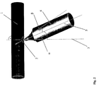
Die Lage des Werkzeugs 4 und die von ihm während eines Bearbeitungszyklus durchlaufene
Bahn sind in der Fig. 2 verdeutlicht. Wie ersichtlich, wird das Werkzeug 4,
dessen Längsachse 5 gegenüber der Mittelsenkrechten 3 des Durchbruchs 2 den Werkzeugwinkel
β aufweist, nach dem Einführen in den Durchbruch 2 durch die
Vorschubeinrichtung 12 gemäß der Darstellung in Fig. 2 nach links gegen den Rand des
Durchbruchs 2 geführt, wobei sich das verjüngende Endes des Werkzeugs im Innern des
Rohrabschnitts unter den Rand des Durchbruchs bewegt. Die Bewegungsrichtung des
Werkzeugs 4 gegen den Rand des Durchbruchs 2 ist dabei so, dass nach dem Auftreffen
des Werkzeugs 4 auf den Rand des Durchbruchs 2 die Spitze des Werkzeugs 4 im
Hohlraum des Rohrstücks zu Anfang teilweise durch den Werkstückmantel, nach dem
Erreichen der kreisförmigen Kontur gänzlich durch die Mantelfläche verdeckt wird.
Anschließend wird das Werkzeug 4 mittels der anderen Vorschubeinrichtung 11 parallel
zu der Geraden, auf der es sich beim Einführen in den Durchbruch 2 bewegt, wieder aus
diesem herausbewegt, wobei es das Material mit nach außen zieht. Das Werkzeug 4 ist
rotationssymmetrisch und besitzt gemäß dem Beispiel einen zylindrischen Spannzapfen.
Wie in der Fig. 2 zu erkennen, ist die Mantelfläche des Werkzeugs im Beispiel zudem im
vorderen sich verjüngenden Bereich leicht gekrümmt. Der jeweils günstigste Verlauf
dieser Freiform - es kann sich auch um einen Kegelstumpf handeln - hängt wieder vom
Material und geometrischen Größen des Werkstücks bzw. des zu fertigenden Fittings ab.The position of the
An der ersten, dem Aushalsen dienenden Arbeitsstation 8 erfährt das Werkzeug 4 beim
Herausfahren aus dem Durchbruch 2 keinen gegen den Rand des Durchbruchs 2 gerichteten
Vorschub mehr. Je nach der Materialbeschaffenheit, der Wandungsstärke des zu
bearbeitenden Rohrabschnitts sowie der Form und der Größe des zu erzeugenden Rohrabgangs
kann hingegen vom Werkzeug 4 an der zweiten Aushalsstation 8', während
seines Herausfahrens aus dem Durchbruch 2, gleichzeitig noch eine gegen den Rand des
Durchbruchs 2 gerichtete Vorschubbewegung ausgeführt werden. Auf diese Weise ist es
zum Beispiel auch möglich, einen sich nach außen erweiternden Rohrabgang zu erzeugen.At the
Die Geometrie des Werkzeugs 4, also insbesondere der Werkzeugwinkel β, mit welchem
sich der Dorn 4 an seinem Ende verjüngt, ist üblicherweise an den Aushalsstationen 8, 8'
gleich. Hingegen kann der Werkzeugeinstellwinkel α, also der Winkel in welchem die
Längsachse 5 des Werkzeugs gegen die Mittelsenkrechte 3 des Durchbruchs 2 geneigt ist,
von der ersten zur zweiten Stufe etwas vergrößert werden.The geometry of the
Für die Herstellung von Fittings aus Stahl der Sorte 1,4571 werden bei einer Wandungsstärke von 1,5 mm und einem Rohrdurchmesser von 15 mm zum Erhalt eines zylinderförmigen Rohrabgangs mit einem dem Rohrdurchmesser entsprechendem Durchmesser beispielsweise folgende Werte vorgegeben:For the production of fittings made of steel of the type 1.4571 at one Wall thickness of 1.5 mm and a tube diameter of 15 mm to obtain a cylindrical pipe outlet with a corresponding to the pipe diameter For example, the following values are specified for the diameter:
An beiden Aushalsstationen 8, 8' erfährt das Werkzeug 4 nach diesem Beispiel während
des Herausbewegens aus dem Durchbruch 2 keinen weiteren Vorschub in radialer
Richtung. Die Vorschübe bleiben an beiden Stationen unverändert. Hingegen weist das
Werkzeug 4 der zweiten Aushalsstation 8' gegenüber dem beim Voraushalsen
verwendeten einen größeren Durchmesser auf. Ansonsten dient die Aufteilung des
Aushalsens auf zwei Verfahrensstufen außerdem der Realisierung eines für den Durchlauf
einer Vielzahl nacheinander zu bearbeitender Werkstücke günstigen Taktregimes. According to this example, the
- 11
- Werkstückworkpiece
- 22
- Durchbruch, Rund- oder LanglochBreakthrough, round or elongated hole
- 33
- MittelsenkrechtePerpendicular bisector
- 44
- Werkzeug, DornTool, mandrel
- 55
- Längsachselongitudinal axis
- 66
- Arbeitsstationworkstation
- 77
- Arbeitsstationworkstation
- 8, 8'8, 8 '
- Arbeitsstationworkstation
- 99
- Arbeitsstationworkstation
- 1010
- WerkstückaufnahmeWorkpiece holder
- 11, 11'11, 11 '
- Vorschubeinrichtungfeeder
- 12, 12'12, 12 '
- Vorschubeinrichtungfeeder
Claims (15)
Applications Claiming Priority (2)
| Application Number | Priority Date | Filing Date | Title |
|---|---|---|---|
| DE10032810 | 2000-06-30 | ||
| DE10032810A DE10032810C2 (en) | 2000-06-30 | 2000-06-30 | Process for producing pipe exits, preferably for the manufacture of fittings from metallic pipe sections, and device suitable therefor |
Publications (2)
| Publication Number | Publication Date |
|---|---|
| EP1166909A1 true EP1166909A1 (en) | 2002-01-02 |
| EP1166909B1 EP1166909B1 (en) | 2004-08-25 |
Family
ID=7647967
Family Applications (1)
| Application Number | Title | Priority Date | Filing Date |
|---|---|---|---|
| EP01250246A Expired - Lifetime EP1166909B1 (en) | 2000-06-30 | 2001-06-28 | Method and apparatus for the making of branched pipes |
Country Status (3)
| Country | Link |
|---|---|
| EP (1) | EP1166909B1 (en) |
| AT (1) | ATE274380T1 (en) |
| DE (2) | DE10032810C2 (en) |
Cited By (2)
| Publication number | Priority date | Publication date | Assignee | Title |
|---|---|---|---|---|
| WO2019228597A1 (en) | 2018-05-29 | 2019-12-05 | ATG Automations-Technik Gröditz GmbH & Co. KG | Producing an outlet on a hollow body |
| CN113680868A (en) * | 2021-07-21 | 2021-11-23 | 王帆 | Aluminum pipe bending instrument |
Citations (5)
| Publication number | Priority date | Publication date | Assignee | Title |
|---|---|---|---|---|
| US3151657A (en) * | 1961-03-22 | 1964-10-06 | United Sheet Metal Co Inc | Sheet metal forming machines |
| EP0007871A1 (en) * | 1978-07-28 | 1980-02-06 | ATELIERS ET CHANTIERS DE BRETAGNE ACB Société anonyme dite: | Machine for the hot forming of collars in convex bottoms |
| SU1310077A1 (en) * | 1985-10-18 | 1987-05-15 | Ленинградский Политехнический Институт Им.М.И.Калинина | Method of producing cylindrical articles |
| JPH0796332A (en) * | 1993-09-29 | 1995-04-11 | Sango Co Ltd | Method and device for burring tube |
| EP0752289A2 (en) * | 1995-06-05 | 1997-01-08 | Enami Seiki Mfg. Co., Ltd. | Branch pipe forming tool and method of forming branch pipe on metal tube with the tool |
Family Cites Families (3)
| Publication number | Priority date | Publication date | Assignee | Title |
|---|---|---|---|---|
| US656425A (en) * | 1899-10-02 | 1900-08-21 | Fritz Schilling | Apparatus for enlarging ajutages of metal tubes. |
| FI800278A (en) * | 1980-01-30 | 1981-07-31 | Serlachius Oy | FLAENSBORRANORDNING |
| NL8104774A (en) * | 1981-10-21 | 1983-05-16 | Drabus Bv | FLUID DRILL. |
-
2000
- 2000-06-30 DE DE10032810A patent/DE10032810C2/en not_active Expired - Fee Related
-
2001
- 2001-06-28 AT AT01250246T patent/ATE274380T1/en not_active IP Right Cessation
- 2001-06-28 EP EP01250246A patent/EP1166909B1/en not_active Expired - Lifetime
- 2001-06-28 DE DE50103373T patent/DE50103373D1/en not_active Expired - Fee Related
Patent Citations (5)
| Publication number | Priority date | Publication date | Assignee | Title |
|---|---|---|---|---|
| US3151657A (en) * | 1961-03-22 | 1964-10-06 | United Sheet Metal Co Inc | Sheet metal forming machines |
| EP0007871A1 (en) * | 1978-07-28 | 1980-02-06 | ATELIERS ET CHANTIERS DE BRETAGNE ACB Société anonyme dite: | Machine for the hot forming of collars in convex bottoms |
| SU1310077A1 (en) * | 1985-10-18 | 1987-05-15 | Ленинградский Политехнический Институт Им.М.И.Калинина | Method of producing cylindrical articles |
| JPH0796332A (en) * | 1993-09-29 | 1995-04-11 | Sango Co Ltd | Method and device for burring tube |
| EP0752289A2 (en) * | 1995-06-05 | 1997-01-08 | Enami Seiki Mfg. Co., Ltd. | Branch pipe forming tool and method of forming branch pipe on metal tube with the tool |
Cited By (3)
| Publication number | Priority date | Publication date | Assignee | Title |
|---|---|---|---|---|
| WO2019228597A1 (en) | 2018-05-29 | 2019-12-05 | ATG Automations-Technik Gröditz GmbH & Co. KG | Producing an outlet on a hollow body |
| CN113680868A (en) * | 2021-07-21 | 2021-11-23 | 王帆 | Aluminum pipe bending instrument |
| CN113680868B (en) * | 2021-07-21 | 2024-05-03 | 淮北徽鼎铝业有限公司 | Aluminum pipe bending instrument |
Also Published As
| Publication number | Publication date |
|---|---|
| DE10032810C2 (en) | 2003-12-04 |
| DE50103373D1 (en) | 2004-09-30 |
| DE10032810A1 (en) | 2002-01-17 |
| ATE274380T1 (en) | 2004-09-15 |
| EP1166909B1 (en) | 2004-08-25 |
Similar Documents
| Publication | Publication Date | Title |
|---|---|---|
| EP2127777A1 (en) | Device and method for generating or processing workpieces from a blank mould, in particular for casting internal profiles or internal gears | |
| EP2279819A2 (en) | Device for mechanically machining tubular or rod-shaped workpieces | |
| EP3645188B1 (en) | Method for producing a bent part and bending machine for performing the method | |
| EP1982777A1 (en) | Cyclic welding machine for welding a tubular blank | |
| DE19816403A1 (en) | Device for forming wire, with a wire brake device | |
| DE2808081A1 (en) | METHOD AND DEVICE FOR MANUFACTURING HELICAL ROTOR BLANKS FOR Eccentric Screw Pumps | |
| DE10032810C2 (en) | Process for producing pipe exits, preferably for the manufacture of fittings from metallic pipe sections, and device suitable therefor | |
| DE19725453C2 (en) | Process for producing a hollow shaft | |
| DE102010041164B4 (en) | Method of making a drill | |
| DE2512854C3 (en) | Process for the production of twist drills or similar tools | |
| DE102006029637B4 (en) | Method and device for bending a cylindrical workpiece | |
| EP0683000A1 (en) | Device for working the surface of a workpiece | |
| DE102009044279B4 (en) | Method for producing a wall connection piece and associated wall connection piece | |
| EP3639946A1 (en) | Connecting element, method and device for producing the same | |
| EP3801944B1 (en) | Producing an outlet on a hollow body | |
| DE102010031607C5 (en) | Gleitflächenbearbeitung an elastically deformed plain bearing shell | |
| DE102008006293A1 (en) | Method and device for bending round tubes and profiles | |
| EP3810353B1 (en) | Roller body for a hydrostatic rolling tool, and hydrostatic rolling tool having said roller body | |
| EP1419840A1 (en) | Device for working, particularly by shaving, the edges of a strip material and laser welding method | |
| WO2021190935A1 (en) | Bending machine | |
| DE102018208020A1 (en) | Method for producing an opening in a hollow body | |
| DE1866721U (en) | DEVICE FOR PUNCHING OR HOLE HOLES, PRIORLY FROM PIPES. | |
| DE4424822A1 (en) | Precision hole production process | |
| DE2230655A1 (en) | CUTTING AND BOERING DEVICE FOR PIPES AND PIPE CUTTING PRODUCED WITH IT | |
| DE1402888A1 (en) | Methods and tools for machining the tips of ballpoint pens or other ball sockets |
Legal Events
| Date | Code | Title | Description |
|---|---|---|---|
| PUAI | Public reference made under article 153(3) epc to a published international application that has entered the european phase |
Free format text: ORIGINAL CODE: 0009012 |
|
| AK | Designated contracting states |
Kind code of ref document: A1 Designated state(s): AT BE CH CY DE DK ES FI FR GB GR IE IT LI LU MC NL PT SE TR |
|
| AX | Request for extension of the european patent |
Free format text: AL;LT;LV;MK;RO;SI |
|
| RAP1 | Party data changed (applicant data changed or rights of an application transferred) |
Owner name: SMB INNOVATIVE PRODUKTE WILDAU GMBH |
|
| 17P | Request for examination filed |
Effective date: 20020626 |
|
| AKX | Designation fees paid |
Free format text: AT BE CH CY DE DK ES FI FR GB GR IE IT LI LU MC NL PT SE TR |
|
| 17Q | First examination report despatched |
Effective date: 20030526 |
|
| GRAP | Despatch of communication of intention to grant a patent |
Free format text: ORIGINAL CODE: EPIDOSNIGR1 |
|
| GRAS | Grant fee paid |
Free format text: ORIGINAL CODE: EPIDOSNIGR3 |
|
| GRAA | (expected) grant |
Free format text: ORIGINAL CODE: 0009210 |
|
| AK | Designated contracting states |
Kind code of ref document: B1 Designated state(s): AT BE CH CY DE DK ES FI FR GB GR IE IT LI LU MC NL PT SE TR |
|
| PG25 | Lapsed in a contracting state [announced via postgrant information from national office to epo] |
Ref country code: IT Free format text: LAPSE BECAUSE OF FAILURE TO SUBMIT A TRANSLATION OF THE DESCRIPTION OR TO PAY THE FEE WITHIN THE PRESCRIBED TIME-LIMIT;WARNING: LAPSES OF ITALIAN PATENTS WITH EFFECTIVE DATE BEFORE 2007 MAY HAVE OCCURRED AT ANY TIME BEFORE 2007. THE CORRECT EFFECTIVE DATE MAY BE DIFFERENT FROM THE ONE RECORDED. Effective date: 20040825 Ref country code: TR Free format text: LAPSE BECAUSE OF FAILURE TO SUBMIT A TRANSLATION OF THE DESCRIPTION OR TO PAY THE FEE WITHIN THE PRESCRIBED TIME-LIMIT Effective date: 20040825 Ref country code: IE Free format text: LAPSE BECAUSE OF FAILURE TO SUBMIT A TRANSLATION OF THE DESCRIPTION OR TO PAY THE FEE WITHIN THE PRESCRIBED TIME-LIMIT Effective date: 20040825 Ref country code: NL Free format text: LAPSE BECAUSE OF FAILURE TO SUBMIT A TRANSLATION OF THE DESCRIPTION OR TO PAY THE FEE WITHIN THE PRESCRIBED TIME-LIMIT Effective date: 20040825 Ref country code: FR Free format text: LAPSE BECAUSE OF FAILURE TO SUBMIT A TRANSLATION OF THE DESCRIPTION OR TO PAY THE FEE WITHIN THE PRESCRIBED TIME-LIMIT Effective date: 20040825 Ref country code: FI Free format text: LAPSE BECAUSE OF FAILURE TO SUBMIT A TRANSLATION OF THE DESCRIPTION OR TO PAY THE FEE WITHIN THE PRESCRIBED TIME-LIMIT Effective date: 20040825 Ref country code: GB Free format text: LAPSE BECAUSE OF FAILURE TO SUBMIT A TRANSLATION OF THE DESCRIPTION OR TO PAY THE FEE WITHIN THE PRESCRIBED TIME-LIMIT Effective date: 20040825 |
|
| REG | Reference to a national code |
Ref country code: GB Ref legal event code: FG4D Free format text: NOT ENGLISH |
|
| RIN1 | Information on inventor provided before grant (corrected) |
Inventor name: KEIL, ULRICH. Inventor name: DROMMER, ROLAND Inventor name: ENGELMANN, ROLF |
|
| REG | Reference to a national code |
Ref country code: CH Ref legal event code: EP |
|
| REG | Reference to a national code |
Ref country code: IE Ref legal event code: FG4D Free format text: GERMAN |
|
| REF | Corresponds to: |
Ref document number: 50103373 Country of ref document: DE Date of ref document: 20040930 Kind code of ref document: P |
|
| PG25 | Lapsed in a contracting state [announced via postgrant information from national office to epo] |
Ref country code: DK Free format text: LAPSE BECAUSE OF FAILURE TO SUBMIT A TRANSLATION OF THE DESCRIPTION OR TO PAY THE FEE WITHIN THE PRESCRIBED TIME-LIMIT Effective date: 20041125 Ref country code: GR Free format text: LAPSE BECAUSE OF FAILURE TO SUBMIT A TRANSLATION OF THE DESCRIPTION OR TO PAY THE FEE WITHIN THE PRESCRIBED TIME-LIMIT Effective date: 20041125 Ref country code: SE Free format text: LAPSE BECAUSE OF FAILURE TO SUBMIT A TRANSLATION OF THE DESCRIPTION OR TO PAY THE FEE WITHIN THE PRESCRIBED TIME-LIMIT Effective date: 20041125 |
|
| PG25 | Lapsed in a contracting state [announced via postgrant information from national office to epo] |
Ref country code: ES Free format text: LAPSE BECAUSE OF FAILURE TO SUBMIT A TRANSLATION OF THE DESCRIPTION OR TO PAY THE FEE WITHIN THE PRESCRIBED TIME-LIMIT Effective date: 20041206 |
|
| NLV1 | Nl: lapsed or annulled due to failure to fulfill the requirements of art. 29p and 29m of the patents act | ||
| GBV | Gb: ep patent (uk) treated as always having been void in accordance with gb section 77(7)/1977 [no translation filed] |
Effective date: 20040825 |
|
| REG | Reference to a national code |
Ref country code: IE Ref legal event code: FD4D |
|
| PG25 | Lapsed in a contracting state [announced via postgrant information from national office to epo] |
Ref country code: AT Free format text: LAPSE BECAUSE OF NON-PAYMENT OF DUE FEES Effective date: 20050628 Ref country code: LU Free format text: LAPSE BECAUSE OF NON-PAYMENT OF DUE FEES Effective date: 20050628 Ref country code: CY Free format text: LAPSE BECAUSE OF FAILURE TO SUBMIT A TRANSLATION OF THE DESCRIPTION OR TO PAY THE FEE WITHIN THE PRESCRIBED TIME-LIMIT Effective date: 20050628 |
|
| PG25 | Lapsed in a contracting state [announced via postgrant information from national office to epo] |
Ref country code: LI Free format text: LAPSE BECAUSE OF NON-PAYMENT OF DUE FEES Effective date: 20050630 Ref country code: MC Free format text: LAPSE BECAUSE OF NON-PAYMENT OF DUE FEES Effective date: 20050630 Ref country code: BE Free format text: LAPSE BECAUSE OF NON-PAYMENT OF DUE FEES Effective date: 20050630 Ref country code: CH Free format text: LAPSE BECAUSE OF NON-PAYMENT OF DUE FEES Effective date: 20050630 |
|
| PLBE | No opposition filed within time limit |
Free format text: ORIGINAL CODE: 0009261 |
|
| STAA | Information on the status of an ep patent application or granted ep patent |
Free format text: STATUS: NO OPPOSITION FILED WITHIN TIME LIMIT |
|
| 26N | No opposition filed |
Effective date: 20050526 |
|
| EN | Fr: translation not filed | ||
| PG25 | Lapsed in a contracting state [announced via postgrant information from national office to epo] |
Ref country code: DE Free format text: LAPSE BECAUSE OF NON-PAYMENT OF DUE FEES Effective date: 20060103 |
|
| REG | Reference to a national code |
Ref country code: CH Ref legal event code: PL |
|
| BERE | Be: lapsed |
Owner name: *SMB INNOVATIVE PRODUKTE WILDAU G.M.B.H. Effective date: 20050630 |
|
| PG25 | Lapsed in a contracting state [announced via postgrant information from national office to epo] |
Ref country code: PT Free format text: LAPSE BECAUSE OF NON-PAYMENT OF DUE FEES Effective date: 20050125 |