EP1164359B1 - Optischer Längenmesssensor mit einer optoelektronischen Anordnung von Photodetektoren - Google Patents
Optischer Längenmesssensor mit einer optoelektronischen Anordnung von Photodetektoren Download PDFInfo
- Publication number
- EP1164359B1 EP1164359B1 EP20010500139 EP01500139A EP1164359B1 EP 1164359 B1 EP1164359 B1 EP 1164359B1 EP 20010500139 EP20010500139 EP 20010500139 EP 01500139 A EP01500139 A EP 01500139A EP 1164359 B1 EP1164359 B1 EP 1164359B1
- Authority
- EP
- European Patent Office
- Prior art keywords
- fringes
- photodetectors
- photodiode
- period
- light
- Prior art date
- Legal status (The legal status is an assumption and is not a legal conclusion. Google has not performed a legal analysis and makes no representation as to the accuracy of the status listed.)
- Expired - Lifetime
Links
Images

Classifications
-
- G—PHYSICS
- G01—MEASURING; TESTING
- G01D—MEASURING NOT SPECIALLY ADAPTED FOR A SPECIFIC VARIABLE; ARRANGEMENTS FOR MEASURING TWO OR MORE VARIABLES NOT COVERED IN A SINGLE OTHER SUBCLASS; TARIFF METERING APPARATUS; MEASURING OR TESTING NOT OTHERWISE PROVIDED FOR
- G01D5/00—Mechanical means for transferring the output of a sensing member; Means for converting the output of a sensing member to another variable where the form or nature of the sensing member does not constrain the means for converting; Transducers not specially adapted for a specific variable
- G01D5/26—Mechanical means for transferring the output of a sensing member; Means for converting the output of a sensing member to another variable where the form or nature of the sensing member does not constrain the means for converting; Transducers not specially adapted for a specific variable characterised by optical transfer means, i.e. using infrared, visible, or ultraviolet light
- G01D5/32—Mechanical means for transferring the output of a sensing member; Means for converting the output of a sensing member to another variable where the form or nature of the sensing member does not constrain the means for converting; Transducers not specially adapted for a specific variable characterised by optical transfer means, i.e. using infrared, visible, or ultraviolet light with attenuation or whole or partial obturation of beams of light
- G01D5/34—Mechanical means for transferring the output of a sensing member; Means for converting the output of a sensing member to another variable where the form or nature of the sensing member does not constrain the means for converting; Transducers not specially adapted for a specific variable characterised by optical transfer means, i.e. using infrared, visible, or ultraviolet light with attenuation or whole or partial obturation of beams of light the beams of light being detected by photocells
- G01D5/36—Forming the light into pulses
-
- G—PHYSICS
- G01—MEASURING; TESTING
- G01D—MEASURING NOT SPECIALLY ADAPTED FOR A SPECIFIC VARIABLE; ARRANGEMENTS FOR MEASURING TWO OR MORE VARIABLES NOT COVERED IN A SINGLE OTHER SUBCLASS; TARIFF METERING APPARATUS; MEASURING OR TESTING NOT OTHERWISE PROVIDED FOR
- G01D5/00—Mechanical means for transferring the output of a sensing member; Means for converting the output of a sensing member to another variable where the form or nature of the sensing member does not constrain the means for converting; Transducers not specially adapted for a specific variable
- G01D5/26—Mechanical means for transferring the output of a sensing member; Means for converting the output of a sensing member to another variable where the form or nature of the sensing member does not constrain the means for converting; Transducers not specially adapted for a specific variable characterised by optical transfer means, i.e. using infrared, visible, or ultraviolet light
- G01D5/32—Mechanical means for transferring the output of a sensing member; Means for converting the output of a sensing member to another variable where the form or nature of the sensing member does not constrain the means for converting; Transducers not specially adapted for a specific variable characterised by optical transfer means, i.e. using infrared, visible, or ultraviolet light with attenuation or whole or partial obturation of beams of light
- G01D5/34—Mechanical means for transferring the output of a sensing member; Means for converting the output of a sensing member to another variable where the form or nature of the sensing member does not constrain the means for converting; Transducers not specially adapted for a specific variable characterised by optical transfer means, i.e. using infrared, visible, or ultraviolet light with attenuation or whole or partial obturation of beams of light the beams of light being detected by photocells
- G01D5/347—Mechanical means for transferring the output of a sensing member; Means for converting the output of a sensing member to another variable where the form or nature of the sensing member does not constrain the means for converting; Transducers not specially adapted for a specific variable characterised by optical transfer means, i.e. using infrared, visible, or ultraviolet light with attenuation or whole or partial obturation of beams of light the beams of light being detected by photocells using displacement encoding scales
- G01D5/34707—Scales; Discs, e.g. fixation, fabrication, compensation
- G01D5/34715—Scale reading or illumination devices
Definitions
- the present patent relates to an optical length measuring device comprising an optoelectronic arrangement of photodetectors as it is defined in the preamble of independent claim 1.
- EP-0843159-A discloses an optical appliance for measuring the displacements or position of an object used in machine tools, the light source of which is an array of diffused light emitting diodes (LED), and it generates a light pattern such as "moirée” fringes whose period (M) is derived from the period of both gratings of the appliance, which varies cyclically in intensity in the direction of the displacement (X) of a scanning grating on a grating of the measuring scale.
- Its photoelectric analyzer is positioned in an image plane, on which the light pattern falls, and configured with a series of elongated photosensitive areas on a semiconductor substrate.
- the photosensitive areas are spaced in the direction of the displacement (X) and in the direction perpendicular (Y) to the length of the scale, and they are arranged in accordance with various electrically interconnected photodetector sets or systems.
- the photosensitive areas of one photodetector system or the other are interposed in series in direction X, following a repeated model, and the distance separating photosensitive areas is related to the period of the light pattern, in order to obtain various electrical output signals without the harmonic distortions due to imprecisions of the gratings.
- the combined signals provide two quasi-sinusoidal signals in quadrature, which are computed to provide a measurement of displacement.
- ES-2029802-T3 discloses an optoelectronic arrangement of photodetectors for measuring relative displacement between a scanning grating and a scale grating of equal or only slightly differing periods, which uses collimated light to obtain fringes of "moirée" light of period M dependent on the periods (p', p") of the gratings.
- the known optoelectronic arrangement comprises at least a complete photodetector system or unit made up of four photosensitive areas or fields of given shape and width and separated in the direction of displacement (X) by a 1/4 fraction of period M, equivalent to an angle equal to 90 degrees relative displacement x .
- the four photosensitve areas are of sinusoidal contour and are interposed in series, oriented half and half in opposition.
- this optoelectronic arrangement is subjected to a Fourier analysis in accordance with x and the bandwidth N , it succeeds in suppressing harmonic distortions of any order by filtration.
- this arrangement of photodetectors when the fringe period varies, it reduces the signal amplitude critically.
- EP-0143525-A discloses a sensor for detecting the position of a movable object, wherein the source is diffuse light and the light detector comprises a set of photocells, arranged in a series layout in the direction of displacement X, of two halves composed of symmetrical photocells in relation to a central axis or barycentre of lighting perpendicular to the direction of displacement.
- the sensitive cells or areas are separated by a periodic distance Pc, and they are of varying height.
- the photocells are classified in four groups, all with the same barycentre of lighting and electrically connected to obtain four signals phase shifted 90° from one another, A-, B+, A+ and B-.
- any error in the relation between the transparent grating period Po and the photocell period Pc has no effect on the electrical signals showing the position of the transparent grating relative to the photocells.
- This known arrangement of photocells is used to resolve the problem of error in the phase shift of the electrical signals generated in the photocells, caused by deviations in the relative assembly position of the transparent grating on the photocells, but it does not solve the problem of reduction of amplitude of the electrical signals, which is produced when the period of the fringes varies. It does not eliminate harmonic distortions completely either.
- De 1950176 discloses an optical encoder with two photodetectors, each comprising two photodiodes with sinusoidally varying sensitive areas.
- the optoelectronic arrangements of the prior art suppress the harmonic distortions of a given bandwidth or all of them, it being necessary to obtain two sinusoidal electrical output signals for computing the pulses and the consequent interpolation of smaller length values than the period p of the measuring scale, for which they have four sensitive areas or photocells arranged one after another in order in direction X, at a given distance or period dependent on the period p of the incident fringes of light.
- the four photodetector units referred to hereinafter as photodiodes, as they are known from the prior art, should be constructed on the image plane of the semiconductor substrate, completing in twos a period p exactly the same as the period of the fringes of light that they receive.
- the analogue electrical measuring signal obtained undergoes significant variations in amplitude in all the optical measuring appliances of the prior art.
- the object of the invention is an optical length measuring device comprising an optoelectronic arrangement of photodetectors , which is the receiver of a cyclic intensity of light fringes, generated by way of a mobile optical element associated with the object whose displacement we want to measure, for conversion into electrical measuring signals, as defined in claim 1.
- the problem solved by the invention is to find the area, shape and distribution of the hotpcells or photodiodes of the optoelectronic arrangement used in the optical length measuring device, in which the pitch of separation between the photodiodes is not dependent on the period of the light fringes, in a wide range of values.
- the incident light fringes generated for measuring length may be obtained by Moiré effect, by Lau effect, by interferometry, or by direct projection of an image from a linear lattice.
- the objective achieved with the invention is that the photodiodes of the optoelectronic arrangement meet the following conditions:
- the optical length measuring device is defined in independent claim 1.
- This device comprises two photodetectors each comprising two photodiodes, while each of the four diodes is made up of a series of photosensitive areas arranged on an image plane of light fringes, spaced at distances depending on a central value of the period of the fringes, but being of a shape, size, number and distribution such that, besides achieving complete suppression of the harmonic distortions in the electrical output signals of each photodiode, the signals are stable and non-dependent on the deviations in the value of the period p of the incident light fringes.
- the optoelectronic arrangement according to the invention also permits the reading of periodic fringes with any light intensity distribution that is periodic.
- the four photodiodes are impressed on the image plane of the optoelectronic arrangement, distributed in two photodetectors or separated halves, to obtain respectively the four sinusoidal signals S( ⁇ ,p) phase shifted 90°, sine+ and sine-, from a half or photodetector, and cos+, cos- from the second half arrangement or photodetector.
- the variable p is the period of the light fringes received on the photodetectors, and ⁇ (theta) the relative displacement of the light fringes.
- One half of the sensitive areas constitutes two photodiodes of a first photodetector, and they are arranged in alternate series one after another in direction X.
- the other half of the sensitive areas, those of a second photodetector are not in series with the first ones, but are arrayed parallel to the first half.
- the distribution f(x, ⁇ ) of the intensity of the light fringes falling upon the image plane of the photodiodes is represented as a Fourier series where x is the variable of the length to be measured in a direction X perpendicular to the fringes of light.
- p is the period of the light fringes
- ⁇ theta
- the two photodetectors are designed for obtaining the electrical signals for the measurement sin x and cos x, their areas being represented by two functions g 1 x and g 2 x , which meet the following conditions (2) and (3):
- the optoelectronic arrangement also solves the problem originated by the reduced amplitude or small amount of electrical signal due to the changing the period of the fringes compared with the prior art arrangements.
- the equations (2) and (3) express that said signal amplitude obtained with the optical length measuring device according to the invention is independent of period p .
- a first photodetector 16, 17 generates the electrical signals in quadrature, sin + and sin -
- a second photodetector 18, 19 generates the signals in quadrature, cos + and cos -.
- the four photodiodes 16-19 are represented in each of the figures 1 and 2, on an image plane 20 which is the receiver of light fringes of period p transmitted in a length measuring optical appliance.
- Each reference numeral 16-19 in figures 1 and 2 indicates the sensitive areas comprised by each of the four photodiodes, which match up with the numbers assigned to the expressions (16), (17), (18), (19) presented and resolved in the description, in order to determine the configuration of each photodiode.
- Each sensitive area 16-19 has an elongated shape of height h , which is variable in descending order from a central sensitive area to one side of the image to the other.
- the sensitive areas 16-19 follow the functions g 1 (x) and g 2 (x) developed below and are dependent on the period p of the light fringes and on the displacement x of the light fringes in the perpendicular direction X , displaced with the movement of the mobile optical element associated with the length that we want to measure.
- Each photodetector comprises two photodiodes 16,17 and 18,19, respectively, the sensitive areas 16 of the first photodiode and the sensitive areas 17 of the second photodiode intercalated alternately, making up a series wherein the bases 21 of the sensitive areas root of their heights h form a straight line in the direction X of the displacement of the light fringes.
- the sensitive areas 18 of the third photodiode and the sensitive areas 19 of the fourth photodiode 16,17, the bases 21' of the of the sensitive areas forming a straight line coinciding with line 21 of the first photodetector 16,17, as in the example in FIG.1, or counterposed to it in the example in FIG. 2, the latter with better utilisation of the area of the image plane 20, as the two photodetectors 16,17 and 18,19 intersect on the image plane 20.
- Equation (7) By operating the equation (6), we obtain an equation (7), which, after simplification, becomes wherein G 1 (k) is the Fourier transform of the function g 1 (x) , the latter representing the area of the first photodetector 16,17.
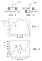
- the solution of equation (8) has to fulfil: and from the conditions expressed by the equations (9) and (10) we extract another condition (11) 2 ⁇ p 1 ⁇ 4 ⁇ p 2 which has to be fulfilled by the value range [p 1 , p 2 ] of the period, such that a value of p between them will not produce a deviation 23 of the phase in quadrature (figure 6) of the electrical signals generated in the photodiodes.
- the characteristics of the photodiodes 16,17 and 18,19 expressed in the equations (2) and (3) respectively are obtained.
- the transformed signal G 1 (k) for the configuration of the first photodetector (16,17), has two values 9,10 shown in fig. 3.
- the inverse Fourier transform of signal G1(k) expresses the area and form of a first photodetector: which fulfils the condition (4),
- the photodiodes having heights h1(x) and h2(x) are indicated with the numerals 16 and 17 and represented in the upper half of figures 1 and 2, and their electrical connection conforms the photodetector 16,17 obtained from the expression (12) of g(x) .
- the electrical signals from the photodiodes having heights h1(x) and h2(x) are deducted.
- the electrical connection of the sensitive areas having heights h3(x) and h4(x) and being indicated with the numerals 18 and 19 conforms the photodetector 18,19 obtained from the expression (15) g 2 (x) , represented in the figures 1 and 2 by the lower half of the sensitive areas. In fig.
- the substrate 20 is represented with the image plane on which the photodetectors of the invention have been inserted, wherein the photodetector g 1 (x) formed by the photodiodes 16 and 17 extends in the direction X of displacement of the fringes.
- the photodetector g 1 (x) formed by the photodiodes 16 and 17 extends in the direction X of displacement of the fringes.
- Each one of the sensitive areas 16-19 has a more or less elongated shape, those of the same photodiode being different sized, and from a straight base 21 according to direction X they extend with heights h1 and h2 in the direction of the light fringes, and with width x in the direction X of the displacement of the light fringes.
- each sensitive area do not necessarily have to be aligned, but only distributed successively along the direction X of displacement, for the incidence of the intensity of the fringes upon their whole area.
- Each photodiode 16,17 is distributed in the examples of figures 1 and 2 so that each sensitive area 16 of them of them alternates with a sensitive area 17 of the second photodiode belonging to the same photodetector.
- the second photodetector made according to the function g 2 (x) formed by the two photodiodes 18,19 extends below the first photodetector 16,17 in the inverted position, starting from its straight bases 21' adjacent to the straight bases 21 of the first photodetector 16,17 and their h3 and h4 extending in the opposite direction to the heights h1 and h2 of the photodiodes 16,17 of the first photodetector,
- Fig. 2 are represented the substrate 20 of the image plane, presenting a more compact second distribution 2 of the sensitive areas of the two photodetectors 16-19.
- the areas of one photodetector and the other are interposed in order to occupy less substrate area, approximately 20% less than distribution 1 in figure 1.
- the electronic arrangement has been implemented in a measuring device constructed with a diffuse light source, where the light fringes are generated between a scale grating with a period equal to 40 ⁇ m and a scanning grating with a period equal to 36.7 ⁇ m.
- the spacing between the image plane of the photodetectors and the support plane of the scanning grating is approximately 25 mm.
- the relative value A/100 of the amplitude 22 of the electrical signals S( ⁇ ,p) obtained by the photodetectors 16,17 and 18,19, not shown in the drawings remains greater than 80% of the maximum value.
- the deviation of value 23 of phase ⁇ in respect of the 90° phase shift between the electrical signals S( ⁇ ,p) remains less than 1°, equivalent to a positioning error between the gratings of less than 0.1 ⁇ m.
Landscapes
- Physics & Mathematics (AREA)
- General Physics & Mathematics (AREA)
- Length Measuring Devices By Optical Means (AREA)
- Optical Transform (AREA)
Claims (2)
- Optischer Apparat zur Längenmessung, der eine optoelektronische Photodetektoren-Anordnung und ausserdem eine Lichtquelle, ein bewegliches optisches Element, das mit der Länge der zu messenden Fortbewegung in Verbindung steht, sowie ein festes optisches Element umfasst, wobei alle Teile ein optisches System bilden, das zyklische Lichtstreifen der Periode p erzeugt, die sich in einer Richtung X senkrecht zu den Lichtstreifen mit einer unmittelbaren Position fortbewegen und auf die optoelektronische Anordnung (1, 2) treffen, und daneben zwei Photodetektoren (16, 17 und 18, 19) enthält, die jeweils zwei Photodioden (16-19) auf einer Bildebene (20) umfassen, die mit dem elektronischen Stromkreis der Längenmessvorrichtung verbunden sind, um - ausgehend von den auftreffenden Lichtstreifen, deren Wert (22) der Amplitude (A) und deren Wert (23) der Phasenverschiebung Ψ das Ergebnis der Längenmessung angeben, mindestens zwei elektrische Signale S(,p) in Quadratur ohne harmonische Verzerrungen zu erzeugen und verwerten, wobei die Photodioden (16-19) auf der Bildebene (20) nach einem Array von in Reihe geschalteten lichtempfindlichen Oberflächen (16,17 und 18,19) in X-Richtung der Fortbewegung der Lichtstreifen verteilt werden, dadurch gekennzeichnet, dass jede Photodiode (16-19) ein und desselben Photodetektors (16,17 oder 18,19) eine Reihe von lichtempfindlichen Oberflächen (16-19) umfasst, die sich von einer geradlinigen Grundfläche (21,21'), deren Form und Grösse für jede Photodiode (16, 18) durch deren Breite X und Höhe h in Bezug auf die Richtung X der Fortbewegung der auftreffenden Streifen mittels einer Funktion g (x) vorgegeben wird, deren jeweilige Gleichungen g1(x) für die erste Photodiode und g2(x) für die zweite Photodiode, welche die erste ergänzt, zwei Werte p1, p2 der Periode p der Lichtstreifen enthalten, die einen weiten Intervall von Werten abgrenzen, aus denen in jeder Photodiode (16-19) ein elektrisches Signal S(,p) erhalten wird, das von der Abweichung der Periode p innerhalb dieses Wertintervalls unabhängig ist.
- Optoelektronische Anordnung der Photodetektoren nach Anspruch 1, bei der die Funktion g ( x), welche die Breite x und die Höhe h der lichtempfindlichen Oberflächen (16-19) der Photodioden des ersten Photodetektors (16, 17) bestimmt, einer Gleichung (12) wie entsprichtund die Abmessungen x und h einer ersten Photodiode (16) sowie die Aufteilung in getrennte lichtempfindliche Oberflächen durch die Gleichung vorgegeben sind,
 während die der zweiten Photodiode (17), die das elektrische Signal mit einem gegenüber der ersten Photodiode (16) umgekehrten Vorzeichen erhält, durch die Gleichung (17) vorgegeben werden

Applications Claiming Priority (2)
| Application Number | Priority Date | Filing Date | Title |
|---|---|---|---|
| ES200001496 | 2000-06-15 | ||
| ES200001496A ES2166717B1 (es) | 2000-06-15 | 2000-06-15 | Disposicion optoelectronica de fotodetectores para la medicion de longitud. |
Publications (2)
| Publication Number | Publication Date |
|---|---|
| EP1164359A1 EP1164359A1 (de) | 2001-12-19 |
| EP1164359B1 true EP1164359B1 (de) | 2005-03-09 |
Family
ID=8493898
Family Applications (1)
| Application Number | Title | Priority Date | Filing Date |
|---|---|---|---|
| EP20010500139 Expired - Lifetime EP1164359B1 (de) | 2000-06-15 | 2001-06-06 | Optischer Längenmesssensor mit einer optoelektronischen Anordnung von Photodetektoren |
Country Status (3)
| Country | Link |
|---|---|
| EP (1) | EP1164359B1 (de) |
| DE (1) | DE60109233T2 (de) |
| ES (1) | ES2166717B1 (de) |
Family Cites Families (4)
| Publication number | Priority date | Publication date | Assignee | Title |
|---|---|---|---|---|
| IT1160210B (it) * | 1983-09-30 | 1987-03-04 | Olivetti & Co Spa | Trasduttore ottico per rilevare la posizione di un organo mobile rispetto ad una struttura fissa |
| DE3616144A1 (de) * | 1986-05-14 | 1987-11-19 | Heidenhain Gmbh Dr Johannes | Fotoelektrische messeinrichtung |
| EP0843159A3 (de) * | 1991-11-06 | 1999-06-02 | Renishaw Transducer Systems Limited | Opto-elektronischer Skalenableseapparat |
| CH690971A5 (de) * | 1994-02-25 | 2001-03-15 | Hera Rotterdam Bv | Verfahren zur Messung und Verwertung einer Verschiebung eines Abtastkopfes gegenüber einer Massverkörperung und optischer Messgeber zur Durchführung dieses Verfahrens. |
-
2000
- 2000-06-15 ES ES200001496A patent/ES2166717B1/es not_active Expired - Fee Related
-
2001
- 2001-06-06 EP EP20010500139 patent/EP1164359B1/de not_active Expired - Lifetime
- 2001-06-06 DE DE2001609233 patent/DE60109233T2/de not_active Expired - Lifetime
Also Published As
| Publication number | Publication date |
|---|---|
| DE60109233T2 (de) | 2006-02-23 |
| ES2166717B1 (es) | 2003-04-16 |
| DE60109233D1 (de) | 2005-04-14 |
| EP1164359A1 (de) | 2001-12-19 |
| ES2166717A1 (es) | 2002-04-16 |
Similar Documents
| Publication | Publication Date | Title |
|---|---|---|
| EP1104543B1 (de) | Vorricthung zum messen von translation,rotation oder geschwindigkeit durch interferenz von lichtstrahlen | |
| JPH0663783B2 (ja) | 光電測定装置 | |
| JPH0245126B2 (de) | ||
| JP5268529B2 (ja) | 変位計測装置及び半導体製造装置 | |
| EP2369303B1 (de) | Optischer Kodierer | |
| JPS60260813A (ja) | 変位測定方法及びその装置 | |
| US10401152B2 (en) | Position detection apparatus, force sensor, and apparatus | |
| EP0801724B1 (de) | Optoelektronischer drehkodierer | |
| JPH09196705A (ja) | 変位測定装置 | |
| JPH07286861A (ja) | 光学変換器および方法 | |
| US8618467B2 (en) | Absolute encoder that detects an absolute position of an object | |
| JPH06109484A (ja) | 信号処理方法及びそれを用いたエンコーダ | |
| KR20060116859A (ko) | 광학식 인코더 | |
| CN113302454A (zh) | 编码器设备 | |
| US5981942A (en) | Optical encoder for detecting relative displacement based on signals having predetermined phase differences | |
| EP0694764B1 (de) | Detektorreihe für interferometrische Messsysteme | |
| EP0636240B1 (de) | Winkel-detektion | |
| US5526114A (en) | Time multiplexed fringe counter | |
| US4231662A (en) | Phase shift correction for displacement measuring systems using quadrature | |
| US5066129A (en) | Optical linear encoder with light quantity calabration | |
| EP1164359A1 (de) | Anordnung optoelektronischer Photodetektoren zur Längenmessung | |
| JPH11118422A (ja) | モアレ縞を用いた寸法測定装置 | |
| JPH09126818A (ja) | 光電測長または測角装置 | |
| CN119687797B (zh) | 一种高精度光栅尺位移解调算法和灵敏度标定方法 | |
| JP2001041730A (ja) | リニヤスケール |
Legal Events
| Date | Code | Title | Description |
|---|---|---|---|
| PUAI | Public reference made under article 153(3) epc to a published international application that has entered the european phase |
Free format text: ORIGINAL CODE: 0009012 |
|
| AK | Designated contracting states |
Kind code of ref document: A1 Designated state(s): AT BE CH CY DE DK ES FI FR GB GR IE IT LI LU MC NL PT SE TR Kind code of ref document: A1 Designated state(s): DE IT |
|
| AX | Request for extension of the european patent |
Free format text: AL;LT;LV;MK;RO;SI |
|
| 17P | Request for examination filed |
Effective date: 20020205 |
|
| AKX | Designation fees paid |
Free format text: DE IT |
|
| 17Q | First examination report despatched |
Effective date: 20040521 |
|
| GRAP | Despatch of communication of intention to grant a patent |
Free format text: ORIGINAL CODE: EPIDOSNIGR1 |
|
| RTI1 | Title (correction) |
Free format text: OPTICAL LENGTH MEASURING DEVICE WITH OPTOELECTRONIC ARRANGEMENT OF PHOTODETECTORS |
|
| RTI1 | Title (correction) |
Free format text: OPTICAL LENGTH MEASURING DEVICE WITH OPTOELECTRONIC ARRANGEMENT OF PHOTODETECTORS |
|
| GRAS | Grant fee paid |
Free format text: ORIGINAL CODE: EPIDOSNIGR3 |
|
| GRAA | (expected) grant |
Free format text: ORIGINAL CODE: 0009210 |
|
| AK | Designated contracting states |
Kind code of ref document: B1 Designated state(s): DE IT |
|
| REG | Reference to a national code |
Ref country code: IE Ref legal event code: FG4D |
|
| REF | Corresponds to: |
Ref document number: 60109233 Country of ref document: DE Date of ref document: 20050414 Kind code of ref document: P |
|
| PLBE | No opposition filed within time limit |
Free format text: ORIGINAL CODE: 0009261 |
|
| STAA | Information on the status of an ep patent application or granted ep patent |
Free format text: STATUS: NO OPPOSITION FILED WITHIN TIME LIMIT |
|
| 26N | No opposition filed |
Effective date: 20051212 |
|
| PGFP | Annual fee paid to national office [announced via postgrant information from national office to epo] |
Ref country code: IT Payment date: 20080623 Year of fee payment: 8 |
|
| PG25 | Lapsed in a contracting state [announced via postgrant information from national office to epo] |
Ref country code: IT Free format text: LAPSE BECAUSE OF NON-PAYMENT OF DUE FEES Effective date: 20090606 |
|
| PGFP | Annual fee paid to national office [announced via postgrant information from national office to epo] |
Ref country code: DE Payment date: 20170628 Year of fee payment: 17 |
|
| REG | Reference to a national code |
Ref country code: DE Ref legal event code: R119 Ref document number: 60109233 Country of ref document: DE |
|
| PG25 | Lapsed in a contracting state [announced via postgrant information from national office to epo] |
Ref country code: DE Free format text: LAPSE BECAUSE OF NON-PAYMENT OF DUE FEES Effective date: 20190101 |