EP1164294A1 - Gasreibungspumpe - Google Patents
Gasreibungspumpe Download PDFInfo
- Publication number
- EP1164294A1 EP1164294A1 EP01110210A EP01110210A EP1164294A1 EP 1164294 A1 EP1164294 A1 EP 1164294A1 EP 01110210 A EP01110210 A EP 01110210A EP 01110210 A EP01110210 A EP 01110210A EP 1164294 A1 EP1164294 A1 EP 1164294A1
- Authority
- EP
- European Patent Office
- Prior art keywords
- gas
- rotor
- gas friction
- rotor component
- friction pump
- Prior art date
- Legal status (The legal status is an assumption and is not a legal conclusion. Google has not performed a legal analysis and makes no representation as to the accuracy of the status listed.)
- Granted
Links
Images



Classifications
-
- F—MECHANICAL ENGINEERING; LIGHTING; HEATING; WEAPONS; BLASTING
- F04—POSITIVE - DISPLACEMENT MACHINES FOR LIQUIDS; PUMPS FOR LIQUIDS OR ELASTIC FLUIDS
- F04D—NON-POSITIVE-DISPLACEMENT PUMPS
- F04D19/00—Axial-flow pumps
- F04D19/02—Multi-stage pumps
- F04D19/04—Multi-stage pumps specially adapted to the production of a high vacuum, e.g. molecular pumps
- F04D19/042—Turbomolecular vacuum pumps
-
- F—MECHANICAL ENGINEERING; LIGHTING; HEATING; WEAPONS; BLASTING
- F04—POSITIVE - DISPLACEMENT MACHINES FOR LIQUIDS; PUMPS FOR LIQUIDS OR ELASTIC FLUIDS
- F04D—NON-POSITIVE-DISPLACEMENT PUMPS
- F04D29/00—Details, component parts, or accessories
- F04D29/26—Rotors specially for elastic fluids
- F04D29/32—Rotors specially for elastic fluids for axial flow pumps
- F04D29/321—Rotors specially for elastic fluids for axial flow pumps for axial flow compressors
- F04D29/324—Blades
-
- F—MECHANICAL ENGINEERING; LIGHTING; HEATING; WEAPONS; BLASTING
- F04—POSITIVE - DISPLACEMENT MACHINES FOR LIQUIDS; PUMPS FOR LIQUIDS OR ELASTIC FLUIDS
- F04D—NON-POSITIVE-DISPLACEMENT PUMPS
- F04D29/00—Details, component parts, or accessories
- F04D29/40—Casings; Connections of working fluid
- F04D29/42—Casings; Connections of working fluid for radial or helico-centrifugal pumps
- F04D29/4206—Casings; Connections of working fluid for radial or helico-centrifugal pumps especially adapted for elastic fluid pumps
- F04D29/4213—Casings; Connections of working fluid for radial or helico-centrifugal pumps especially adapted for elastic fluid pumps suction ports
Definitions
- the invention relates to a gas friction pump according to the preamble of FIG. 1. Claim.
- Gas friction pumps of various types are used to convey gases known. Their mode of operation in the molecular flow range is based on the Transmission of impulses from moving walls to the gas particles.
- the first Gas friction pump of this type was introduced by Gaede. More technical Modifications while maintaining the basic principle are constructions of Siegbahn, Holweck and Becker. The latter is known as a turbomolecular pump has been successful in wide areas of technology and science proven. It is therefore used as an example for the description of the present invention used.
- the pumping speed of turbomolecular pumps is next to the internal structure of the Pump and speed also significantly through the input cross section of the Intake flange determined.
- the dimensions of the intake flange are determined by Standard regulations set to a few sizes. Should be like this specified suction cross-section, greater suction capacity can be achieved, can increase the diameter of the discs and thus the pumping area become. This leads to a design in which the diameter of the discs is larger is the diameter of the intake flange. It is obvious that that Pumping speed is limited by the cross section of the intake flange. This acts like a flow resistance between the top rotor disc and Recipient.
- the object of the invention is largely this flow resistance to overcome and so the pumping speed, which is determined by the diameter of the the upper rotor disk is given maximum use.
- Embodiments can optimally adapt the modified rotor component the recipient and its connection to the intake flange. This also opens up the possibility of partially over the rotor component Let the suction flange protrude into the recipient.
- Stator components compared to the modified rotor component can be pump-active Structures. This will make the transition from the smaller to the larger Diameter of the modified rotor component made even more effective.
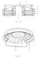
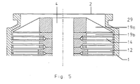
- FIGS. 2a, 3a, 4a and 5 show further embodiments which are shown in FIGS. 2a, 3a, 4a and 5 in section and in FIGS. 2b, 3b and 4b in the respective associated Perspective are shown.
- Fig. 1 shows a gas friction pump with the housing 1, which has a suction opening 2 for connecting a recipient and a gas outlet opening 3 is provided.
- the rotor shaft 4 is fixed in bearings 5 and 6 and is driven by the motor 7 driven.
- the rotor components 12 are fastened on the rotor shaft 4. These are with provided with a pump-active structure and effect with the stator components 14, which are also provided with a pump-active structure, the pump effect.
- the Intake opening has an inner diameter that is smaller than that Outside diameter of the rotor and stator components.
- a modified rotor component 16 is attached according to the invention, which is shown in FIGS. 2a and 2b as a detail from FIG. 1 in a sectional and perspective view.
- This rotor component is provided with a gas-producing structure. Its radial expansion increases from the suction opening in the direction of the other rotor and stator components and can finally reach their radial expansion.
- the radial expansion can increase either in stages, as in FIGS. 1, 2a and 2b or continuously in conical 17 in FIGS. 3a and 3b or dome-shaped 18 in FIGS. 4a and 4b. Mixed forms of the design types are also possible.
- a multi-part design of the modified component 19a, 19b as in FIG. 5 can be sensible for reasons of the manufacturing possibilities.
- the possibility should also be mentioned that the radial expansion of the modified rotor component is smaller than that of the other rotor components and remains constant in the axial direction.
- stator components 26-29 can also be used pump-active structure. These stator components are either called Individual components or formed as part of the housing 1.
Landscapes
- Engineering & Computer Science (AREA)
- Mechanical Engineering (AREA)
- General Engineering & Computer Science (AREA)
- Non-Positive Displacement Air Blowers (AREA)
Abstract
Description
Schließlich soll noch die Möglichkeit erwähnt werden, dass die radiale Ausdehnung des abgewandelten Rotorbauteils kleiner ist als die der übrigen Rotorbauteile und in axialer Richtung konstant bleibt.
Claims (11)
- Gasreibungspumpe, bestehend aus einem Gehäuse (1) mit Ansaugöffnung (2) zum Anschluss eines Rezipienten und Gasaustrittsöffnung (3), wobei sich in dem Gehäuse pumpaktive Rotor- (12) und Statorbauteile (14) zur Förderung von Gasen und zur Erzeugung eines Druckverhältnisses befinden und der Innendurchmesser der Ansaugöffnung (2) kleiner ist als der Durchmesser der pumpaktiven Rotor- und Statorbauteile, dadurch gekennzeichnet, dass ein abgewandeltes Rotorbauteil (16, 17, 18, 19a, 19b) mit gasfördernder Struktur auf der Seite der Ansaugöffnung (2) vorhanden ist, dessen radiale Ausdehnung von der Ansaugöffnung aus in Richtung der übrigen Rotor- und Statorbauteile zunimmt.
- Gasreibungspumpe nach Anspruch 1, dadurch gekennzeichnet, dass die radiale Ausdehnung des abgewandelten Rotorbauteils stufenförmig zunimmt.
- Gasreibungspumpe nach Anspruch 1, dadurch gekennzeichnet, dass die radiale Ausdehnung des abgewandelten Rotorbauteils kontinuierlich zunimmt.
- Gasreibungspumpe nach einem der Ansprüche 1 - 3, dadurch gekennzeichnet, dass das abgewandelte Rotorbauteil ganz oder teilweise eine konische Bauform aufweist.
- Gasreibungspumpe nach einem der Ansprüche 1 - 3, dadurch gekennzeichnet, dass das Rotorbauteil ganz oder teilweise eine kuppelförmige Bauform aufweist.
- Gasreibungspumpe nach einem der vorangehenden Ansprüche, dadurch gekennzeichnet, dass die radiale Ausdehnung des abgewandelten Rotorbaueils auf der dem Statorbauteil zugewandten Seite der radialen Ausdehnung der übrigen Rotorbauteile entspricht.
- Gasreibungspumpe nach einem der vorangehenden Ansprüche, dadurch gekennzeichnet, dass das abgewandelte Rotorbauteil über die Ansaugöffnung hinaus teilweise in den Rezipienten hineinragt.
- Gasreibungspumpe nach einem der vorangehenden Ansprüche, dadurch gekennzeichnet, dass das abgewandelte Rotorbauteil aus mehreren Teilen besteht.
- Gasreibungspumpe, besehend aus einem Gehäuse (1) mit Ansaugöffnung (2) zum Anschluss eines Rezipienten und Gasaustrittsöffnung (3), wobei sich in dem Gehäuse pumpaktive Rotor- (12) und Statorbauteile (14) zur Förderung von Gasen und zur Erzeugung eines Druckverhältnisses befinden und der Innendurchmesser der Ansaugöffnung (2) kleiner ist der Durchmesser der pumpaktiven Rotor- und Statorbauteile, dadurch gekennzeichnet, dass ein abgewandeltes Rotorbauteil mit gasfördernder Struktur auf der Seite der Ansaugöffnung (2) vorhanden ist, dessen radiale Ausdehnung kleiner ist als die der übrigen Rotor- und Statorbauteile.
- Gasreibungspumpe nach einem der vorangehenden Ansprüche, dadurch gekennzeichnet, dass sich gegenüber dem abgewandelten Rotorbauteil ein Statorbauteil (26, 27, 28, 29) mit pumpaktiver Struktur befindet.
- Gasreibungspumpe nach Anspruch 10, dadurch gekennzeichnet, dass das Statorbauteil (26, 27, 28, 29) als Teil des Gehäuses (1) ausgebildet ist.
Applications Claiming Priority (4)
| Application Number | Priority Date | Filing Date | Title |
|---|---|---|---|
| DE10023799 | 2000-05-15 | ||
| DE10023799 | 2000-05-15 | ||
| DE10111546 | 2001-03-10 | ||
| DE10111546A DE10111546A1 (de) | 2000-05-15 | 2001-03-10 | Gasreibungspumpe |
Publications (2)
| Publication Number | Publication Date |
|---|---|
| EP1164294A1 true EP1164294A1 (de) | 2001-12-19 |
| EP1164294B1 EP1164294B1 (de) | 2003-09-10 |
Family
ID=26005688
Family Applications (1)
| Application Number | Title | Priority Date | Filing Date |
|---|---|---|---|
| EP20010110210 Expired - Lifetime EP1164294B1 (de) | 2000-05-15 | 2001-04-25 | Gasreibungspumpe |
Country Status (2)
| Country | Link |
|---|---|
| EP (1) | EP1164294B1 (de) |
| JP (1) | JP5149472B2 (de) |
Cited By (1)
| Publication number | Priority date | Publication date | Assignee | Title |
|---|---|---|---|---|
| EP1341291A3 (de) * | 2002-02-28 | 2004-08-18 | Pfeiffer Vacuum GmbH | Maschine mit schnelldrehendem Rotor |
Citations (5)
| Publication number | Priority date | Publication date | Assignee | Title |
|---|---|---|---|---|
| DE2757599A1 (de) * | 1977-12-23 | 1979-06-28 | Kernforschungsz Karlsruhe | Turbo-molekularpumpe |
| US5165872A (en) * | 1989-07-20 | 1992-11-24 | Leybold Aktiengesellschaft | Gas friction pump having a bell-shaped rotor |
| US5553998A (en) * | 1992-05-16 | 1996-09-10 | Leybold Ag | Gas friction vacuum pump having at least three differently configured pump stages releasably connected together |
| US5577883A (en) * | 1992-06-19 | 1996-11-26 | Leybold Aktiengesellschaft | Gas friction vacuum pump having a cooling system |
| US5927940A (en) * | 1996-08-23 | 1999-07-27 | Pfeiffer Vacuum Gmbh | Double-flow gas friction pump |
Family Cites Families (7)
| Publication number | Priority date | Publication date | Assignee | Title |
|---|---|---|---|---|
| NL8105614A (nl) * | 1981-12-14 | 1983-07-01 | Ultra Centrifuge Nederland Nv | Hoog-vacuum moleculair pomp. |
| JPS6214198U (de) * | 1985-07-10 | 1987-01-28 | ||
| JPS62168994A (ja) * | 1985-12-26 | 1987-07-25 | Morihiko Kimata | 高真空排気装置 |
| JPS6456597U (de) * | 1987-10-05 | 1989-04-07 | ||
| JPH02153294A (ja) * | 1988-12-05 | 1990-06-12 | Nippon Soken Inc | 可変容量型真空ポンプ |
| JP4104098B2 (ja) * | 1999-03-31 | 2008-06-18 | エドワーズ株式会社 | 真空ポンプ |
| JP3961155B2 (ja) * | 1999-05-28 | 2007-08-22 | Bocエドワーズ株式会社 | 真空ポンプ |
-
2001
- 2001-04-17 JP JP2001117878A patent/JP5149472B2/ja not_active Expired - Lifetime
- 2001-04-25 EP EP20010110210 patent/EP1164294B1/de not_active Expired - Lifetime
Patent Citations (5)
| Publication number | Priority date | Publication date | Assignee | Title |
|---|---|---|---|---|
| DE2757599A1 (de) * | 1977-12-23 | 1979-06-28 | Kernforschungsz Karlsruhe | Turbo-molekularpumpe |
| US5165872A (en) * | 1989-07-20 | 1992-11-24 | Leybold Aktiengesellschaft | Gas friction pump having a bell-shaped rotor |
| US5553998A (en) * | 1992-05-16 | 1996-09-10 | Leybold Ag | Gas friction vacuum pump having at least three differently configured pump stages releasably connected together |
| US5577883A (en) * | 1992-06-19 | 1996-11-26 | Leybold Aktiengesellschaft | Gas friction vacuum pump having a cooling system |
| US5927940A (en) * | 1996-08-23 | 1999-07-27 | Pfeiffer Vacuum Gmbh | Double-flow gas friction pump |
Cited By (1)
| Publication number | Priority date | Publication date | Assignee | Title |
|---|---|---|---|---|
| EP1341291A3 (de) * | 2002-02-28 | 2004-08-18 | Pfeiffer Vacuum GmbH | Maschine mit schnelldrehendem Rotor |
Also Published As
| Publication number | Publication date |
|---|---|
| JP5149472B2 (ja) | 2013-02-20 |
| JP2002005079A (ja) | 2002-01-09 |
| EP1164294B1 (de) | 2003-09-10 |
Similar Documents
| Publication | Publication Date | Title |
|---|---|---|
| WO2011038884A1 (de) | Diagonalventilator | |
| DE29516599U1 (de) | Reibungsvakuumpumpe mit Zwischeneinlaß | |
| EP1441128B1 (de) | Vakuumpumpsystem | |
| EP1706645B1 (de) | Mehrstufige reibungsvakuumpumpe | |
| EP1067290B1 (de) | Vakuumpumpe | |
| DE10008691B4 (de) | Gasreibungspumpe | |
| EP1165965A1 (de) | Seitenkanalverdichter | |
| EP1205667B1 (de) | Gasreibungspumpe | |
| EP0363503A1 (de) | Pumpenstufe für eine Hochvakuumpumpe | |
| EP1164294B1 (de) | Gasreibungspumpe | |
| EP1243796A2 (de) | Vakuumpumpe | |
| EP0118027A2 (de) | Selbstansaugende Seitenkanalpumpe | |
| DE202009006872U1 (de) | Radiallüfter | |
| DE10111546A1 (de) | Gasreibungspumpe | |
| EP0825346B1 (de) | Eingangsstufe für eine zweiflutige Gasreibungspumpe | |
| EP1081387B1 (de) | Vakuumpumpe | |
| DE10224604B4 (de) | Evakuierungseinrichtung | |
| EP2342464A1 (de) | Seitenkanalgebläse, insbesondere senkundärluftgebläse für eine verbrennungskraftmaschine | |
| DE102015224603A1 (de) | Läufer für eine Pumpvorrichtung | |
| EP2100041A1 (de) | Motorkreiselpumpe | |
| EP1307370B1 (de) | Pumpenaggregat für eine hydraulische fahrzeugbremsanlage | |
| DE189064C (de) | ||
| EP1178211A2 (de) | Steuerscheibe insbesondere für eine Flügelzellenpumpe | |
| DE3314651C2 (de) | Vakuumpumpe | |
| DE202018105024U1 (de) | Verdichter mit einer Axialdruckausgleichsvorrichtung |
Legal Events
| Date | Code | Title | Description |
|---|---|---|---|
| PUAI | Public reference made under article 153(3) epc to a published international application that has entered the european phase |
Free format text: ORIGINAL CODE: 0009012 |
|
| AK | Designated contracting states |
Kind code of ref document: A1 Designated state(s): AT BE CH CY DE DK ES FI FR GB GR IE IT LI LU MC NL PT SE TR Kind code of ref document: A1 Designated state(s): CH DE FR GB IT LI NL |
|
| AX | Request for extension of the european patent |
Free format text: AL;LT;LV;MK;RO;SI |
|
| 17P | Request for examination filed |
Effective date: 20020510 |
|
| AKX | Designation fees paid |
Free format text: CH DE FR GB IT LI NL |
|
| GRAH | Despatch of communication of intention to grant a patent |
Free format text: ORIGINAL CODE: EPIDOS IGRA |
|
| GRAS | Grant fee paid |
Free format text: ORIGINAL CODE: EPIDOSNIGR3 |
|
| GRAA | (expected) grant |
Free format text: ORIGINAL CODE: 0009210 |
|
| AK | Designated contracting states |
Kind code of ref document: B1 Designated state(s): CH DE FR GB IT LI NL |
|
| REG | Reference to a national code |
Ref country code: GB Ref legal event code: FG4D Free format text: NOT ENGLISH |
|
| REG | Reference to a national code |
Ref country code: CH Ref legal event code: EP |
|
| REF | Corresponds to: |
Ref document number: 50100591 Country of ref document: DE Date of ref document: 20031016 Kind code of ref document: P |
|
| REG | Reference to a national code |
Ref country code: IE Ref legal event code: FG4D Free format text: GERMAN |
|
| REG | Reference to a national code |
Ref country code: CH Ref legal event code: NV Representative=s name: PFEIFFER VACUUM (SCHWEIZ) AG |
|
| GBT | Gb: translation of ep patent filed (gb section 77(6)(a)/1977) | ||
| REG | Reference to a national code |
Ref country code: IE Ref legal event code: FD4D |
|
| ET | Fr: translation filed | ||
| PLBE | No opposition filed within time limit |
Free format text: ORIGINAL CODE: 0009261 |
|
| STAA | Information on the status of an ep patent application or granted ep patent |
Free format text: STATUS: NO OPPOSITION FILED WITHIN TIME LIMIT |
|
| 26N | No opposition filed |
Effective date: 20040614 |
|
| PGFP | Annual fee paid to national office [announced via postgrant information from national office to epo] |
Ref country code: NL Payment date: 20150331 Year of fee payment: 15 |
|
| REG | Reference to a national code |
Ref country code: FR Ref legal event code: PLFP Year of fee payment: 16 |
|
| REG | Reference to a national code |
Ref country code: NL Ref legal event code: MM Effective date: 20160501 |
|
| PG25 | Lapsed in a contracting state [announced via postgrant information from national office to epo] |
Ref country code: NL Free format text: LAPSE BECAUSE OF NON-PAYMENT OF DUE FEES Effective date: 20160501 |
|
| REG | Reference to a national code |
Ref country code: FR Ref legal event code: PLFP Year of fee payment: 17 |
|
| REG | Reference to a national code |
Ref country code: FR Ref legal event code: PLFP Year of fee payment: 18 |
|
| PGFP | Annual fee paid to national office [announced via postgrant information from national office to epo] |
Ref country code: CH Payment date: 20180328 Year of fee payment: 18 |
|
| REG | Reference to a national code |
Ref country code: CH Ref legal event code: PL |
|
| PG25 | Lapsed in a contracting state [announced via postgrant information from national office to epo] |
Ref country code: CH Free format text: LAPSE BECAUSE OF NON-PAYMENT OF DUE FEES Effective date: 20190430 Ref country code: LI Free format text: LAPSE BECAUSE OF NON-PAYMENT OF DUE FEES Effective date: 20190430 |
|
| PGFP | Annual fee paid to national office [announced via postgrant information from national office to epo] |
Ref country code: FR Payment date: 20200320 Year of fee payment: 20 |
|
| PGFP | Annual fee paid to national office [announced via postgrant information from national office to epo] |
Ref country code: DE Payment date: 20200320 Year of fee payment: 20 |
|
| PGFP | Annual fee paid to national office [announced via postgrant information from national office to epo] |
Ref country code: IT Payment date: 20200128 Year of fee payment: 20 Ref country code: GB Payment date: 20200402 Year of fee payment: 20 |
|
| REG | Reference to a national code |
Ref country code: DE Ref legal event code: R071 Ref document number: 50100591 Country of ref document: DE |
|
| REG | Reference to a national code |
Ref country code: GB Ref legal event code: PE20 Expiry date: 20210424 |
|
| PG25 | Lapsed in a contracting state [announced via postgrant information from national office to epo] |
Ref country code: GB Free format text: LAPSE BECAUSE OF EXPIRATION OF PROTECTION Effective date: 20210424 |