EP1164270A1 - Cooling device of liquid cooled internal combustion engine - Google Patents
Cooling device of liquid cooled internal combustion engine Download PDFInfo
- Publication number
- EP1164270A1 EP1164270A1 EP01901477A EP01901477A EP1164270A1 EP 1164270 A1 EP1164270 A1 EP 1164270A1 EP 01901477 A EP01901477 A EP 01901477A EP 01901477 A EP01901477 A EP 01901477A EP 1164270 A1 EP1164270 A1 EP 1164270A1
- Authority
- EP
- European Patent Office
- Prior art keywords
- pump
- blower
- map
- internal combustion
- combustion engine
- Prior art date
- Legal status (The legal status is an assumption and is not a legal conclusion. Google has not performed a legal analysis and makes no representation as to the accuracy of the status listed.)
- Granted
Links
Images




Classifications
-
- F—MECHANICAL ENGINEERING; LIGHTING; HEATING; WEAPONS; BLASTING
- F01—MACHINES OR ENGINES IN GENERAL; ENGINE PLANTS IN GENERAL; STEAM ENGINES
- F01P—COOLING OF MACHINES OR ENGINES IN GENERAL; COOLING OF INTERNAL-COMBUSTION ENGINES
- F01P7/00—Controlling of coolant flow
- F01P7/02—Controlling of coolant flow the coolant being cooling-air
- F01P7/04—Controlling of coolant flow the coolant being cooling-air by varying pump speed, e.g. by changing pump-drive gear ratio
- F01P7/048—Controlling of coolant flow the coolant being cooling-air by varying pump speed, e.g. by changing pump-drive gear ratio using electrical drives
-
- F—MECHANICAL ENGINEERING; LIGHTING; HEATING; WEAPONS; BLASTING
- F01—MACHINES OR ENGINES IN GENERAL; ENGINE PLANTS IN GENERAL; STEAM ENGINES
- F01P—COOLING OF MACHINES OR ENGINES IN GENERAL; COOLING OF INTERNAL-COMBUSTION ENGINES
- F01P7/00—Controlling of coolant flow
- F01P7/14—Controlling of coolant flow the coolant being liquid
- F01P7/16—Controlling of coolant flow the coolant being liquid by thermostatic control
- F01P7/164—Controlling of coolant flow the coolant being liquid by thermostatic control by varying pump speed
-
- F—MECHANICAL ENGINEERING; LIGHTING; HEATING; WEAPONS; BLASTING
- F01—MACHINES OR ENGINES IN GENERAL; ENGINE PLANTS IN GENERAL; STEAM ENGINES
- F01P—COOLING OF MACHINES OR ENGINES IN GENERAL; COOLING OF INTERNAL-COMBUSTION ENGINES
- F01P7/00—Controlling of coolant flow
- F01P7/14—Controlling of coolant flow the coolant being liquid
- F01P2007/146—Controlling of coolant flow the coolant being liquid using valves
-
- F—MECHANICAL ENGINEERING; LIGHTING; HEATING; WEAPONS; BLASTING
- F01—MACHINES OR ENGINES IN GENERAL; ENGINE PLANTS IN GENERAL; STEAM ENGINES
- F01P—COOLING OF MACHINES OR ENGINES IN GENERAL; COOLING OF INTERNAL-COMBUSTION ENGINES
- F01P2023/00—Signal processing; Details thereof
- F01P2023/08—Microprocessor; Microcomputer
-
- F—MECHANICAL ENGINEERING; LIGHTING; HEATING; WEAPONS; BLASTING
- F01—MACHINES OR ENGINES IN GENERAL; ENGINE PLANTS IN GENERAL; STEAM ENGINES
- F01P—COOLING OF MACHINES OR ENGINES IN GENERAL; COOLING OF INTERNAL-COMBUSTION ENGINES
- F01P2025/00—Measuring
- F01P2025/04—Pressure
-
- F—MECHANICAL ENGINEERING; LIGHTING; HEATING; WEAPONS; BLASTING
- F01—MACHINES OR ENGINES IN GENERAL; ENGINE PLANTS IN GENERAL; STEAM ENGINES
- F01P—COOLING OF MACHINES OR ENGINES IN GENERAL; COOLING OF INTERNAL-COMBUSTION ENGINES
- F01P2025/00—Measuring
- F01P2025/08—Temperature
-
- F—MECHANICAL ENGINEERING; LIGHTING; HEATING; WEAPONS; BLASTING
- F01—MACHINES OR ENGINES IN GENERAL; ENGINE PLANTS IN GENERAL; STEAM ENGINES
- F01P—COOLING OF MACHINES OR ENGINES IN GENERAL; COOLING OF INTERNAL-COMBUSTION ENGINES
- F01P2025/00—Measuring
- F01P2025/08—Temperature
- F01P2025/13—Ambient temperature
-
- F—MECHANICAL ENGINEERING; LIGHTING; HEATING; WEAPONS; BLASTING
- F01—MACHINES OR ENGINES IN GENERAL; ENGINE PLANTS IN GENERAL; STEAM ENGINES
- F01P—COOLING OF MACHINES OR ENGINES IN GENERAL; COOLING OF INTERNAL-COMBUSTION ENGINES
- F01P2025/00—Measuring
- F01P2025/60—Operating parameters
- F01P2025/62—Load
-
- F—MECHANICAL ENGINEERING; LIGHTING; HEATING; WEAPONS; BLASTING
- F01—MACHINES OR ENGINES IN GENERAL; ENGINE PLANTS IN GENERAL; STEAM ENGINES
- F01P—COOLING OF MACHINES OR ENGINES IN GENERAL; COOLING OF INTERNAL-COMBUSTION ENGINES
- F01P2025/00—Measuring
- F01P2025/60—Operating parameters
- F01P2025/66—Vehicle speed
-
- F—MECHANICAL ENGINEERING; LIGHTING; HEATING; WEAPONS; BLASTING
- F01—MACHINES OR ENGINES IN GENERAL; ENGINE PLANTS IN GENERAL; STEAM ENGINES
- F01P—COOLING OF MACHINES OR ENGINES IN GENERAL; COOLING OF INTERNAL-COMBUSTION ENGINES
- F01P2060/00—Cooling circuits using auxiliaries
- F01P2060/14—Condenser
-
- F—MECHANICAL ENGINEERING; LIGHTING; HEATING; WEAPONS; BLASTING
- F01—MACHINES OR ENGINES IN GENERAL; ENGINE PLANTS IN GENERAL; STEAM ENGINES
- F01P—COOLING OF MACHINES OR ENGINES IN GENERAL; COOLING OF INTERNAL-COMBUSTION ENGINES
- F01P7/00—Controlling of coolant flow
- F01P7/14—Controlling of coolant flow the coolant being liquid
- F01P7/16—Controlling of coolant flow the coolant being liquid by thermostatic control
- F01P7/167—Controlling of coolant flow the coolant being liquid by thermostatic control by adjusting the pre-set temperature according to engine parameters, e.g. engine load, engine speed
Definitions
- the present invention relates to a cooling system for a liquid-cooled internal combustion engine appropriately used for a cooling system for, for example, a water-cooled internal combustion engine mounted on an automobile.
- Japanese Unexamined Patent Publication No. 5-231148 discloses a conventional cooling system for controlling a temperature of coolant of a liquid-cooled internal combustion engine to an appropriate value.
- a pump 500 which is operated independently from the liquid-cooled internal combustion engine 100, and a flow control valve 400.
- the pump 500 and the flow control valve 400 are controlled by the control means (electronic control unit) 600 according to the temperature T wi of the coolant at the inlet to the liquid-cooled internal combustion engine 100 and the temperature T wo of the coolant at the outlet and also according to the state of a load given to the liquid-cooled internal combustion engine 100.
- control means electronic control unit
- the flow rate of the discharge from the pump 500 and the degree of opening of the flow control valve 400 are controlled so that the temperature of the coolant can be optimized.
- the operation is conducted as follows.
- the temperature of the coolant is controlled so that it can be lowered. Therefore, the degree of opening of the flow control valve 400 and the duty ratio (or rotational speed) of the pump 500 are raised so that the flow rate of coolant flowing in the radiator 200 can be increased and the radiating effect can be increased.
- the influence of the change in the flow rate in the radiator 200 upon the change in the radiating effect of the radiator 200 is decreased as the flow rate in the radiator is increased.
- the blower 230 is controlled in such a manner that it is only turned on and off by the coolant temperature switch 231, which is insufficient to optimize the cooling effect.
- the present invention has been accomplished to solve the above problems. It is an object of the present invention to provide a cooling system for a liquid-cooled internal combustion engine in which the cooling effect determined by the combination of a pump with a blower is optimized according to the state of a load given to the liquid-cooled internal combustion engine so that the necessary cooling effect can be obtained from the pump and the blower and, at the same time, the power consumption can be reduced.
- the present invention adopts the following technical means.
- An embodiment of the present invention is a cooling system for a liquid-cooled internal combustion engine comprising: a radiator (200) from which coolant flows toward a liquid-cooled internal combustion engine (100) after the coolant flowing out from the liquid-cooled internal combustion engine (100) has been cooled in the radiator (200); a pump (500) for circulating coolant being operated independently from the liquid-cooled internal combustion engine (100); a blower (230) for blowing air to the radiator (200); a control means (600) for controlling the operations of the pump (500) and the blower (230), wherein the control means (600) determines the combination of the cooling effect of the pump (500) and that of the blower (230) for satisfying the necessary cooling effect according to a load given to the liquid-cooled internal combustion engine (100), and also the control means (600) controls the pump (500) and the blower (230) so that the sum (L c ) of the power consumption of the pump (500) and that of the blower (230) can be substantially minimized.
- control means (600) further comprises: a first map for determining a target coolant temperature (T map ) determined according to a load given to the liquid-cooled internal combustion engine (100); and a second map for determining quantities of control of the pump (500) and the blower (230) so as to make the temperature of coolant converge upon the target coolant temperature (T map ), wherein a flow rate of discharge from the pump (500) and a quantity of air blown by the blower (230) are controlled by the quantities, for control of the pump (500) and the blower (230), which are determined by the second map, and wherein the sum (L c ) of the power consumption of the pump (500) and that of the blower (230) is substantially minimized, and wherein feedback control is conducted so that the temperature of coolant becomes the target coolant temperature (T map ).
- T map target coolant temperature
- the temperature of coolant to be controlled is determined, and the combination of the necessary cooling effect of the pump (500) and that of the blower (230) is determined. Therefore, the temperature of coolant can be appropriately controlled at all times. Further, the sum (L c ) of the power consumption of the pump (500) and that of the blower (230) can be controlled so that the sum (L c ) is substantially minimized. Therefore, the power consumption of the entire cooling system can be reduced.
- the degree of opening of the flow control valve (400) is controlled to adjust the flow rate of coolant flowing in the radiator (200). Due to the foregoing, the power consumption of the entire cooling system can be further reduced.
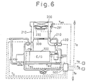
- Fig. 1 is a schematic illustration showing the entire cooling system of the present embodiment.
- the radiator 200 is a heat exchanger for cooling the cooling water circulating in the liquid-cooled internal combustion engine 100 (which will be referred to as an engine hereinafter).
- This radiator 200 is provided with a blower 230 for blowing air.
- the blower 230 is of a type in which air is sucked from the radiator 200 side.
- the drive motor of the blower 230 is of a variable-power type in which the rotational speed of the drive motor can be continuously changed so as to adjust a quantity of air to be blown when the duty ratio of voltage applied to the drive motor is changed. As the duty ratio is changed, power consumption of the blower 230 is also changed.
- the engine 100 and the radiator 200 are connected with each other by the radiator circuit 210 in which cooling water is circulated.
- a bypass circuit 300 for cooling water from the engine 100 to bypass the radiator 200 so that the cooling water can flow onto the outlet side of the radiator 200 in the radiator circuit 210.
- a flow control valve 400 for controlling a flow rate of cooling water circulating in the radiator 200 (which will be referred to as a radiator flow rate V r hereinafter) and also for controlling a flow rate of cooling water circulating in the bypass circuit 300 (which will be referred to as a bypass flow rate V b hereinafter).
- an electrically operated pump 500 (which will be referred to as a pump hereinafter) which operates independently from the engine 100 and circulates cooling water.
- the pump 500 is of a variable-power type in which the duty ratio of this pump 500 is changed so that the rotational speed of the pump 500 can be continuously changed so as to adjust a flow rate of discharge. As the duty ratio is changed, the power consumption of the pump 500 is also changed.
- the flow rate control valve 400 includes a valve which is opened and closed by a motor.
- the degree ⁇ of opening of the valve is changed, the flow rate can be divided into the radiator flow rate V r and the bypass flow rate V b . That is, when the degree ⁇ of opening of the valve is 0%, the radiator flow rate V r becomes 0 and the bypass flow rate V b becomes maximum, and when the degree ⁇ of opening of the valve is 100%, the radiator flow rate V r becomes maximum and the bypass flow rate V b becomes minimum.
- an electronic control unit 600 (which will be referred to as ECU hereinafter) for controlling the pump 500, blower 230 and flow rate control valve 400.
- detection signals are inputted from the pressure sensor 610 (pressure detecting means) for detecting pressure P a in the suction tube of the engine 100 (which will be referred to as suction pressure hereinafter), and also inputted from the rotary sensor 624 (rotational speed detecting means) for detecting the rotational speed N e of the engine 100, the vehicle speed sensor 625 (speed detecting means) for detecting the running speed V v of a vehicle (which will be referred to as a vehicle speed hereinafter), the outside-air-temperature sensor 626 (temperature detecting means) for detecting the outside air temperature T a , the water temperature sensor 621 (temperature detecting means) for detecting the water temperature T p of cooling water flowing into the pump 500, the potentiometer 424 (opening degree detecting means) for detecting the degree ⁇ of valve opening
- ECU 600 conducts the map control described later according to these signals so as to control the pump 500, blower 230 and flow rate control valve 400.
- ECU 600 includes a counter (not shown in the drawing) for counting the number N of readings of the target water temperature T map (described later) which is read in according to the detection signals sent from the various sensors 610, 624, 625, 626, 621 and also from the air-conditioner 700.
- step S50 When the ignition switch (not shown) of a vehicle is turned on, electricity is supplied to ECU 600, and ECU 600 starts its operation.
- step S50 the counter is reset, and the number N of reading is set at 0.
- step S100 the detecting signals of various sensors 610, 624, 625, 626, 621 and the detecting signal of the air-conditioner 700 are read in. Since a load given to the engine 100 has an influence on the temperature T p of cooling water, the load given to the engine 100 is detected by using the suction pressure P a and the vehicle speed V v as parameters. The larger these parameters are, the heavier the load on the engine 100 is.
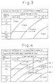
- step S110 the target water temperature T map is read in from the water temperature control map which forms the first map shown in Fig. 3.
- the cooling water temperature T p to be controlled is previously allotted according to the outside air temperature T a , the operating state of the air-conditioner 700, the suction pressure P a and the vehicle speed V v .
- the target water temperatures of T map 1 to T map 4 are previously allotted according to the suction pressure P a and the vehicle speed V v . For example, when the suction pressure P a is high (i.e. when the degree of opening of the throttle valve of the engine 100 is high) and the vehicle speed V v is high, the load on the engine 100 is heavy.
- the target water temperature T map is set low.
- the suction pressure P a is low (i.e. when the degree of opening of the throttle valve is low) and the vehicle speed V v is low, the load on the engine 100 is light. Therefore, the target water temperature T map is set high. That is, on the water temperature control map, the target water temperatures are allotted for T map 1 to T map 4 in order from a low value to a high value.
- a point at which the suction pressure, which has been read in from the pressure sensor 610, crosses the vehicle speed, which has been read in from the vehicle speed sensor 625, on the map is read in as the target water temperature T map .
- the target water temperature becomes T map 2 when the outside air temperature is T a 1 and the air-conditioner 700 is operated and when the suction pressure is P a 1 and the vehicle speed is V v 1.
- step S112 the number N of readings of various detecting signals is set at N + 1.
- step S115 it is judged whether or not the number N of reading is 1. If the number N of reading is 1, it is judged that the state of operation is immediately after the engine 100 has been started, and the program proceeds to step S120. When it is judged that the number N of reading is not 1, the program proceeds to step S130 because it is unnecessary to conduct the process in the step S120 described below.
- step S120 the basic duty ratio of the pump 500 and that of the blower 230 are determined as initial values from a map not shown, and the pump 500 and the blower 230 are set in motion.
- the higher the duty ratio of the blower 230 the more the rotational speed of the blower is increased, so that the flow rate of the air blown to the radiator 200 is increased, and the power consumption of the blower 230 itself is increased.
- step S130 it is judged whether or not the water temperature T p of cooling water in the radiator circuit 210, which is detected by the water temperature sensor 621, is within a predetermined range (in the range of ⁇ 2 degree in this embodiment) in which the target water temperature T map is used as a reference value.
- a predetermined range in the range of ⁇ 2 degree in this embodiment
- the program proceeds to step S180 so that the cooling effect of the cooling system can be optimized and the water temperature T p can be adjusted to the target water temperature T map .
- step S180 it is further judged whether or not the water temperature T p is higher than the target water temperature T map .
- the flow control valve 400 is preferentially operated and the degree ⁇ of opening of the valve is increased by a predetermined value. Due to the foregoing, the water temperature T p is decreased because the flow rate V r of the radiator is increased and the radiating effect of the radiator 200 is increased.
- step S200 it is judged whether or not the degree ⁇ of opening of the valve is 100%.
- step S210 the duty ratio of the pump 500 and that of the blower 230 are changed by a predetermined value, so that the rotational speed of the pump 500 and that of the blower 230 are changed.
- control is conducted in such a manner that the duty ratio of the pump 500 is increased so as to increase the rotational speed of the pump for increasing the flow rate of discharge, and the duty ratio of the blower 230 is increased so as to increase the rotational speed of the blower for increasing the air blown by the blower.
- step S200 when the degree ⁇ of opening of the valve is not 100%, the degree ⁇ of opening of the valve in Step S190 is maintained.
- step S180 when it is judged that the water temperature T p is not higher than the target water temperature T map , that is, when it is judged that the water temperature T p is lower than the target water temperature T map , the program proceeds to step S220, and in order to reduce the power consumption of the cooling system, the pump 500 and the blower 230 are preferentially operated so as to change the respective duty ratio by a predetermined value, so that the rotational speed of the pump 500 and that of the blower 230 are changed.
- control is conducted in such a manner that in order to increase the water temperature T p , the duty ratio of the pump 500 is decreased so as to decrease the rotational speed of the pump for decreasing the flow rate of discharge, and the duty ratio of the blower 230 is decreased so as to decrease the rotational speed of the blower for decreasing the air blown by the blower.
- step S230 it is judged whether or not the duty ratio of the pump 500 and that of the blower 230 have reached the minimum values.
- step S240 When the duty ratio of the pump 500 and that of the blower 230 have reached the minimum values, in step S240, the degree ⁇ of opening of the flow rate control valve 400 is decreased by a predetermined value so as to reduce the flow rate V r of the radiator and to reduce the radiating effect of the radiator 200 so that the water temperature T p can be increased.
- step S230 when the duty ratio of the pump 500 and that of the blower 230 have not reached the minimum values, the duty ratio of the pump 500 and that of the blower 230 which are controlled in step S220 are maintained. Since the steps S200, S210, S230 and S240 repeatedly return to step S100, feedback control is conducted so that the water temperature T p converges upon the target water temperature T map .
- step S130 when it is judged that the water temperature T p is put into a predetermined range of the target water temperature T map by the feedback control conducted on the water temperature T p , the program proceeds to step S140.
- the duty ratio corresponding to the pump 500 and the duty ratio corresponding to the blower 230 are determined so that the sum L c of the power consumption of the pump 500 and that of the blower 230 can be substantially minimized, and then each of the pump 500 and the blower 230 is operated at the respective determined duty ratio.
- the power control map is made for each outside air temperature T a and operation state of the air-conditioner 700.
- the power control map shows a combination of the operation duty ratio of the pump 500 with the operation duty ratio of the blower 230 satisfying the target water temperature T map at that time according to the state of a load given to the engine 100.
- the point L cmin at which the sum L c of the power consumptions of both of them can be substantially minimized, can be elicited by using the power control map (In the present application, "The sum (L c ) of the power consumptions is substantially minimum" means that the sum (L c ) of the power consumptions is in a range of the minimum point + 70W.).
- the inventors utilized the fact that the pump 500 and the blower 230 can be operated independently from the engine 100 and also focussed on the combined cooling effect and the combined power consumption of the both of them. That is, as shown in Fig. 5, of course, the more the flow rate of the pump 500 is increased, the more the power consumption of the pump 500 is increased. On the other hand, the power consumption of the blower 230, which is necessary for keeping the water temperature at T p A when the engine is given a load A, can be reduced in a region in which the flow rate is high, which is contrary to the case of the pump 500.
- the pump 500 and the blower 230 are operated at the point of flow rate "a" and the water temperature is kept at T p A
- the flow rate of the pump 500 is increased to the point "b"
- the power consumption of the pump 500 is also increased as shown by the arrow "d”.
- the flow rate V r of the radiator is increased, so that the radiating effect of the radiator 200 is increased. Therefore, in order to keep the water temperature at T p A, the flow rate of the air blown by the blower 230 may be reduced corresponding to the increase in the radiating effect. Accordingly, the power consumption of the blower 230 is reduced as shown by the arrow "e".
- Fig. 4 shows each point L cmin at which the sum L c of the power consumptions becomes minimum for each parameter of the load of the engine 100.
- load 1 to load 5 are made to be parameters, and the minimum values L cmin 1 to L cmin 5 for each load are shown in the map.
- step S140 ECU 600 gives the pump duty ratio D p and the blower duty ratio D s corresponding to this L cmin 3 respectively to the pump 500 and the blower 230, so that the pump 500 and the blower 230 can be operated.
- the water temperature to be controlled (the target water temperature T map ) is determined according to the state of a load given to the engine 100, and the operating state of the pump 500 and that of the blower 230 can be adjusted to an appropriate combination thereof. Therefore, the temperature of the cooling water can be appropriately control at all times. Further, it is possible to conduct control so that the sum L c of the power consumption of the pump 500 and that of the blower 230 can be substantially minimized. Accordingly, the power consumption of the entire cooling system can be reduced.
- the suction pressure P a and the vehicle speed V v are used as a parameter for detecting the load of the engine 100, as long as it is a parameter expressing the state of an engine and the running state of a vehicle, which have an influence on the cooling water temperature T p , for example, the rotational speed of the engine 100, the degree of opening of the throttle valve or the quantity of the air taken in can be also used as a parameter.
Landscapes
- Engineering & Computer Science (AREA)
- Chemical & Material Sciences (AREA)
- Combustion & Propulsion (AREA)
- Mechanical Engineering (AREA)
- General Engineering & Computer Science (AREA)
- Air-Conditioning For Vehicles (AREA)
- Cooling, Air Intake And Gas Exhaust, And Fuel Tank Arrangements In Propulsion Units (AREA)
Abstract
Description
Claims (3)
- A cooling system for a liquid-cooled internal combustion engine comprising:a radiator (200) from which coolant flows out toward a liquid-cooled internal combustion engine (100) after the coolant flowing out from the liquid-cooled internal combustion engine (100) has been cooled by the radiator (200);a pump (500) for circulating coolant being operated independently from the liquid-cooled internal combustion engine (100);a blower (230) for blowing air to the radiator (200);a control means (600) for controlling the operations of the pump (500) and the blower (230), whereinthe control means (600) determines the combination of the cooling effect of the pump (500) and that of the blower (230) for satisfying the necessary cooling effect according to a load given to the liquid-cooled internal combustion engine (100), and also the control means (600) controls the pump (500) and the blower (230) so that the sum (Lc) of the power consumption of the pump (500) and that of the blower (230) can be substantially minimized.
- A cooling system for a liquid-cooled internal combustion engine, according to claim 1, the control means (600) further comprising:a first map for determining a target coolant temperature (Tmap) determined according to a load given to the liquid-cooled internal combustion engine (100); anda second map for determining quantities of control of the pump (500) and the blower (230) so as to converge the temperature of coolant upon the target coolant temperature (Tmap), whereina flow rate of discharge of the pump (500) and a quantity of air blown by the blower (230) are controlled by the quantities, for control of the pump (500) and the blower (230), which are determined by the second map, and wherein the sum (Lc) of the power consumption of the pump (500) and that of the blower (230) is substantially minimized, and wherein feedback control is conducted so that the temperature of coolant becomes the target coolant temperature (Tmap).
- A cooling system for a liquid-cooled internal combustion engine, according to claim 1 or 2, further comprising:a bypass circuit (300) by which coolant flowing out from the liquid-cooled internal combustion engine (100) bypasses the radiator (200) so that the coolant can be guided to the outlet side of the radiator (200); anda flow rate control valve (400) for controlling a bypass flow rate (Vb) of coolant circulating in the bypass circuit (300) and a radiator flow rate (Vr) of coolant circulating in the radiator (200), whereinthe degree of opening of the flow rate control valve (400) is controlled according to a load on the liquid-cooled internal combustion engine (100).
Applications Claiming Priority (3)
| Application Number | Priority Date | Filing Date | Title |
|---|---|---|---|
| JP2000011408 | 2000-01-20 | ||
| JP2000011408A JP4140160B2 (en) | 2000-01-20 | 2000-01-20 | Cooling device for liquid-cooled internal combustion engine |
| PCT/JP2001/000366 WO2001053673A1 (en) | 2000-01-20 | 2001-01-19 | Cooling device of liquid cooled internal combustion engine |
Publications (3)
| Publication Number | Publication Date |
|---|---|
| EP1164270A1 true EP1164270A1 (en) | 2001-12-19 |
| EP1164270A4 EP1164270A4 (en) | 2006-03-22 |
| EP1164270B1 EP1164270B1 (en) | 2012-06-13 |
Family
ID=18539274
Family Applications (1)
| Application Number | Title | Priority Date | Filing Date |
|---|---|---|---|
| EP01901477A Expired - Lifetime EP1164270B1 (en) | 2000-01-20 | 2001-01-19 | Cooling device of liquid cooled internal combustion engine |
Country Status (4)
| Country | Link |
|---|---|
| US (1) | US6520125B2 (en) |
| EP (1) | EP1164270B1 (en) |
| JP (1) | JP4140160B2 (en) |
| WO (1) | WO2001053673A1 (en) |
Cited By (5)
| Publication number | Priority date | Publication date | Assignee | Title |
|---|---|---|---|---|
| WO2005017326A1 (en) * | 2003-08-08 | 2005-02-24 | Daimlerchrysler Ag | Heat management for an internal combustion engine |
| WO2010116108A1 (en) * | 2009-04-09 | 2010-10-14 | Renault Sas | Cooling device for a motor vehicle |
| WO2013082400A1 (en) | 2011-12-01 | 2013-06-06 | Paccar Inc | Systems and methods for controlling a variable speed water pump |
| EP2787191A3 (en) * | 2013-04-02 | 2015-01-21 | Yamada Manufacturing Co., Ltd. | Control apparatus of electric water pump |
| CN105370378A (en) * | 2014-08-18 | 2016-03-02 | 株式会社山田制作所 | Control device of electric water pump |
Families Citing this family (10)
| Publication number | Priority date | Publication date | Assignee | Title |
|---|---|---|---|---|
| US7182048B2 (en) * | 2002-10-02 | 2007-02-27 | Denso Corporation | Internal combustion engine cooling system |
| US7421983B1 (en) * | 2007-03-26 | 2008-09-09 | Brunswick Corporation | Marine propulsion system having a cooling system that utilizes nucleate boiling |
| US8430068B2 (en) * | 2007-05-31 | 2013-04-30 | James Wallace Harris | Cooling system having inlet control and outlet regulation |
| DE112010005367B4 (en) * | 2010-03-09 | 2017-12-14 | Toyota Jidosha Kabushiki Kaisha | MACHINE COOLER |
| WO2012086056A1 (en) * | 2010-12-24 | 2012-06-28 | トヨタ自動車株式会社 | Vehicle and control method for vehicle |
| DE102014015638A1 (en) | 2014-10-22 | 2016-04-28 | GM Global Technology Operations LLC (n. d. Gesetzen des Staates Delaware) | Controlling a coolant pump and / or a control valve of a cooling system for a ... |
| CN106285907A (en) * | 2016-10-19 | 2017-01-04 | 潍柴动力股份有限公司 | The control method of a kind of engine temperature, Apparatus and system |
| US20190093547A1 (en) * | 2017-09-22 | 2019-03-28 | GM Global Technology Operations LLC | Method and system for coolant temperature control in a vehicle propulsion system |
| CN114458437A (en) * | 2022-03-10 | 2022-05-10 | 潍柴动力股份有限公司 | Water pump control method and device |
| CN115573806B (en) * | 2022-09-07 | 2025-05-06 | 赛力斯集团股份有限公司 | Electronic water pump cooling system control method |
Family Cites Families (8)
| Publication number | Priority date | Publication date | Assignee | Title |
|---|---|---|---|---|
| JPS5874824A (en) * | 1981-10-29 | 1983-05-06 | Nissan Motor Co Ltd | Cooling device of engine |
| JPS58124017A (en) * | 1982-01-19 | 1983-07-23 | Nippon Denso Co Ltd | Cooling system controller of engine |
| JP3044502B2 (en) | 1992-02-19 | 2000-05-22 | 本田技研工業株式会社 | Engine cooling system controller |
| DE69325044T2 (en) | 1992-02-19 | 1999-09-30 | Honda Giken Kogyo K.K., Tokio/Tokyo | Machine cooling system |
| JPH05321665A (en) | 1992-05-22 | 1993-12-07 | Suzuki Motor Corp | Electric fan device for vehicles |
| DE19508102C1 (en) * | 1995-03-08 | 1996-07-25 | Volkswagen Ag | Method for regulating a cooling circuit of an internal combustion engine, in particular for motor vehicles |
| JPH0979211A (en) * | 1995-09-12 | 1997-03-25 | Aisin Seiki Co Ltd | Vehicle cooling system |
| DE19719792B4 (en) * | 1997-05-10 | 2004-03-25 | Behr Gmbh & Co. | Method and device for regulating the temperature of a medium |
-
2000
- 2000-01-20 JP JP2000011408A patent/JP4140160B2/en not_active Expired - Fee Related
-
2001
- 2001-01-19 EP EP01901477A patent/EP1164270B1/en not_active Expired - Lifetime
- 2001-01-19 WO PCT/JP2001/000366 patent/WO2001053673A1/en not_active Ceased
- 2001-09-19 US US09/955,717 patent/US6520125B2/en not_active Expired - Lifetime
Cited By (10)
| Publication number | Priority date | Publication date | Assignee | Title |
|---|---|---|---|---|
| WO2005017326A1 (en) * | 2003-08-08 | 2005-02-24 | Daimlerchrysler Ag | Heat management for an internal combustion engine |
| WO2010116108A1 (en) * | 2009-04-09 | 2010-10-14 | Renault Sas | Cooling device for a motor vehicle |
| FR2944238A1 (en) * | 2009-04-09 | 2010-10-15 | Renault Sas | COOLING DEVICE FOR MOTOR VEHICLE |
| WO2013082400A1 (en) | 2011-12-01 | 2013-06-06 | Paccar Inc | Systems and methods for controlling a variable speed water pump |
| EP2785995A4 (en) * | 2011-12-01 | 2015-05-27 | Paccar Inc | SYSTEMS AND METHODS FOR CONTROLLING A VARIABLE SPEED WATER PUMP |
| US9416720B2 (en) | 2011-12-01 | 2016-08-16 | Paccar Inc | Systems and methods for controlling a variable speed water pump |
| US10119453B2 (en) | 2011-12-01 | 2018-11-06 | Paccar Inc | Systems and methods for controlling a variable speed water pump |
| US10914227B2 (en) | 2011-12-01 | 2021-02-09 | Paccar Inc | Systems and methods for controlling a variable speed water pump |
| EP2787191A3 (en) * | 2013-04-02 | 2015-01-21 | Yamada Manufacturing Co., Ltd. | Control apparatus of electric water pump |
| CN105370378A (en) * | 2014-08-18 | 2016-03-02 | 株式会社山田制作所 | Control device of electric water pump |
Also Published As
| Publication number | Publication date |
|---|---|
| EP1164270A4 (en) | 2006-03-22 |
| JP4140160B2 (en) | 2008-08-27 |
| EP1164270B1 (en) | 2012-06-13 |
| US6520125B2 (en) | 2003-02-18 |
| US20020035971A1 (en) | 2002-03-28 |
| JP2001207846A (en) | 2001-08-03 |
| WO2001053673A1 (en) | 2001-07-26 |
Similar Documents
| Publication | Publication Date | Title |
|---|---|---|
| EP1164270A1 (en) | Cooling device of liquid cooled internal combustion engine | |
| US6374780B1 (en) | Electric waterpump, fluid control valve and electric cooling fan strategy | |
| US6314920B1 (en) | Cooling apparatus for liquid-cooled internal combustion engine | |
| US5529025A (en) | Cooling system for an internal-combustion engine of a motor vehicle comprising a thermostatic valve which contains an electrically heatable expansion element | |
| US6082626A (en) | Cooling water circuit system | |
| JP4337207B2 (en) | Cooling device for liquid-cooled internal combustion engine | |
| EP1279800B1 (en) | Engine cooling apparatus | |
| GB2392492A (en) | A cooling system for a diesel engine featuring an electronically controlled valve | |
| JP2004360509A (en) | Cooling device for internal combustion engine | |
| CN113898603A (en) | Finished automobile fan control system and method | |
| JP2004529287A (en) | Method of monitoring cooling fluid circuit of internal combustion engine | |
| US6260766B1 (en) | Heating apparatus for vehicle | |
| EP0841203A2 (en) | Heating apparatus for vehicle | |
| US6557502B2 (en) | Vehicle air conditioner with heat storage tank | |
| JP4337214B2 (en) | Cooling device for liquid-cooled internal combustion engine | |
| JP4029638B2 (en) | Cooling device for heat generating equipment | |
| EP1279801A2 (en) | Engine cooling system | |
| JP4337212B2 (en) | Cooling device for liquid-cooled internal combustion engine | |
| JPH0930243A (en) | Heating system | |
| JP4604858B2 (en) | Vehicle heating system | |
| JP2005533223A (en) | Internal combustion engine coolant temperature control method and apparatus | |
| JPH05263641A (en) | Revolution speed control device for vehicular cooling fan | |
| JP2001171365A (en) | Engine cooling system for vehicles | |
| JP3931705B2 (en) | Heating equipment cooling device | |
| JP2526569B2 (en) | Speed control method for cooling fan of internal combustion engine |
Legal Events
| Date | Code | Title | Description |
|---|---|---|---|
| PUAI | Public reference made under article 153(3) epc to a published international application that has entered the european phase |
Free format text: ORIGINAL CODE: 0009012 |
|
| 17P | Request for examination filed |
Effective date: 20010918 |
|
| AK | Designated contracting states |
Kind code of ref document: A1 Designated state(s): AT BE CH CY DE DK ES FI FR GB GR IE IT LI LU MC NL PT SE TR |
|
| RBV | Designated contracting states (corrected) |
Designated state(s): DE FR |
|
| A4 | Supplementary search report drawn up and despatched |
Effective date: 20060203 |
|
| 17Q | First examination report despatched |
Effective date: 20080919 |
|
| GRAP | Despatch of communication of intention to grant a patent |
Free format text: ORIGINAL CODE: EPIDOSNIGR1 |
|
| GRAS | Grant fee paid |
Free format text: ORIGINAL CODE: EPIDOSNIGR3 |
|
| GRAA | (expected) grant |
Free format text: ORIGINAL CODE: 0009210 |
|
| AK | Designated contracting states |
Kind code of ref document: B1 Designated state(s): DE FR |
|
| REG | Reference to a national code |
Ref country code: DE Ref legal event code: R096 Ref document number: 60146696 Country of ref document: DE Effective date: 20120809 |
|
| PLBE | No opposition filed within time limit |
Free format text: ORIGINAL CODE: 0009261 |
|
| STAA | Information on the status of an ep patent application or granted ep patent |
Free format text: STATUS: NO OPPOSITION FILED WITHIN TIME LIMIT |
|
| 26N | No opposition filed |
Effective date: 20130314 |
|
| REG | Reference to a national code |
Ref country code: DE Ref legal event code: R097 Ref document number: 60146696 Country of ref document: DE Effective date: 20130314 |
|
| REG | Reference to a national code |
Ref country code: FR Ref legal event code: PLFP Year of fee payment: 16 |
|
| REG | Reference to a national code |
Ref country code: FR Ref legal event code: PLFP Year of fee payment: 17 |
|
| REG | Reference to a national code |
Ref country code: FR Ref legal event code: PLFP Year of fee payment: 18 |
|
| PGFP | Annual fee paid to national office [announced via postgrant information from national office to epo] |
Ref country code: DE Payment date: 20180122 Year of fee payment: 18 |
|
| PGFP | Annual fee paid to national office [announced via postgrant information from national office to epo] |
Ref country code: FR Payment date: 20180119 Year of fee payment: 18 |
|
| REG | Reference to a national code |
Ref country code: DE Ref legal event code: R119 Ref document number: 60146696 Country of ref document: DE |
|
| PG25 | Lapsed in a contracting state [announced via postgrant information from national office to epo] |
Ref country code: DE Free format text: LAPSE BECAUSE OF NON-PAYMENT OF DUE FEES Effective date: 20190801 Ref country code: FR Free format text: LAPSE BECAUSE OF NON-PAYMENT OF DUE FEES Effective date: 20190131 |