EP1164254A2 - Optimized steam turbine peaking cycles utilizing steam bypass and related process - Google Patents
Optimized steam turbine peaking cycles utilizing steam bypass and related process Download PDFInfo
- Publication number
- EP1164254A2 EP1164254A2 EP01305144A EP01305144A EP1164254A2 EP 1164254 A2 EP1164254 A2 EP 1164254A2 EP 01305144 A EP01305144 A EP 01305144A EP 01305144 A EP01305144 A EP 01305144A EP 1164254 A2 EP1164254 A2 EP 1164254A2
- Authority
- EP
- European Patent Office
- Prior art keywords
- steam
- turbine
- steam turbine
- high pressure
- supplemental
- Prior art date
- Legal status (The legal status is an assumption and is not a legal conclusion. Google has not performed a legal analysis and makes no representation as to the accuracy of the status listed.)
- Granted
Links
- 238000000034 method Methods 0.000 title claims abstract 9
- 238000010304 firing Methods 0.000 claims abstract description 19
- 238000011084 recovery Methods 0.000 claims abstract description 17
- 230000000153 supplemental effect Effects 0.000 claims description 39
- 238000011144 upstream manufacturing Methods 0.000 claims 2
- 239000007789 gas Substances 0.000 description 13
- 238000010586 diagram Methods 0.000 description 8
- XLYOFNOQVPJJNP-UHFFFAOYSA-N water Substances O XLYOFNOQVPJJNP-UHFFFAOYSA-N 0.000 description 5
- 239000000446 fuel Substances 0.000 description 3
- 230000003466 anti-cipated effect Effects 0.000 description 2
- 230000015556 catabolic process Effects 0.000 description 2
- 230000003750 conditioning effect Effects 0.000 description 2
- 230000007423 decrease Effects 0.000 description 2
- 238000006731 degradation reaction Methods 0.000 description 2
- 239000002918 waste heat Substances 0.000 description 2
- 238000009835 boiling Methods 0.000 description 1
- 230000000052 comparative effect Effects 0.000 description 1
- 238000010276 construction Methods 0.000 description 1
- 230000009977 dual effect Effects 0.000 description 1
- 230000005611 electricity Effects 0.000 description 1
- 239000000463 material Substances 0.000 description 1
- 239000000203 mixture Substances 0.000 description 1
- 238000005457 optimization Methods 0.000 description 1
Images



Classifications
-
- F—MECHANICAL ENGINEERING; LIGHTING; HEATING; WEAPONS; BLASTING
- F01—MACHINES OR ENGINES IN GENERAL; ENGINE PLANTS IN GENERAL; STEAM ENGINES
- F01K—STEAM ENGINE PLANTS; STEAM ACCUMULATORS; ENGINE PLANTS NOT OTHERWISE PROVIDED FOR; ENGINES USING SPECIAL WORKING FLUIDS OR CYCLES
- F01K23/00—Plants characterised by more than one engine delivering power external to the plant, the engines being driven by different fluids
- F01K23/02—Plants characterised by more than one engine delivering power external to the plant, the engines being driven by different fluids the engine cycles being thermally coupled
- F01K23/06—Plants characterised by more than one engine delivering power external to the plant, the engines being driven by different fluids the engine cycles being thermally coupled combustion heat from one cycle heating the fluid in another cycle
- F01K23/10—Plants characterised by more than one engine delivering power external to the plant, the engines being driven by different fluids the engine cycles being thermally coupled combustion heat from one cycle heating the fluid in another cycle with exhaust fluid of one cycle heating the fluid in another cycle
- F01K23/106—Plants characterised by more than one engine delivering power external to the plant, the engines being driven by different fluids the engine cycles being thermally coupled combustion heat from one cycle heating the fluid in another cycle with exhaust fluid of one cycle heating the fluid in another cycle with water evaporated or preheated at different pressures in exhaust boiler
-
- F—MECHANICAL ENGINEERING; LIGHTING; HEATING; WEAPONS; BLASTING
- F01—MACHINES OR ENGINES IN GENERAL; ENGINE PLANTS IN GENERAL; STEAM ENGINES
- F01K—STEAM ENGINE PLANTS; STEAM ACCUMULATORS; ENGINE PLANTS NOT OTHERWISE PROVIDED FOR; ENGINES USING SPECIAL WORKING FLUIDS OR CYCLES
- F01K23/00—Plants characterised by more than one engine delivering power external to the plant, the engines being driven by different fluids
- F01K23/02—Plants characterised by more than one engine delivering power external to the plant, the engines being driven by different fluids the engine cycles being thermally coupled
- F01K23/06—Plants characterised by more than one engine delivering power external to the plant, the engines being driven by different fluids the engine cycles being thermally coupled combustion heat from one cycle heating the fluid in another cycle
- F01K23/10—Plants characterised by more than one engine delivering power external to the plant, the engines being driven by different fluids the engine cycles being thermally coupled combustion heat from one cycle heating the fluid in another cycle with exhaust fluid of one cycle heating the fluid in another cycle
- F01K23/103—Plants characterised by more than one engine delivering power external to the plant, the engines being driven by different fluids the engine cycles being thermally coupled combustion heat from one cycle heating the fluid in another cycle with exhaust fluid of one cycle heating the fluid in another cycle with afterburner in exhaust boiler
-
- Y—GENERAL TAGGING OF NEW TECHNOLOGICAL DEVELOPMENTS; GENERAL TAGGING OF CROSS-SECTIONAL TECHNOLOGIES SPANNING OVER SEVERAL SECTIONS OF THE IPC; TECHNICAL SUBJECTS COVERED BY FORMER USPC CROSS-REFERENCE ART COLLECTIONS [XRACs] AND DIGESTS
- Y02—TECHNOLOGIES OR APPLICATIONS FOR MITIGATION OR ADAPTATION AGAINST CLIMATE CHANGE
- Y02E—REDUCTION OF GREENHOUSE GAS [GHG] EMISSIONS, RELATED TO ENERGY GENERATION, TRANSMISSION OR DISTRIBUTION
- Y02E20/00—Combustion technologies with mitigation potential
- Y02E20/16—Combined cycle power plant [CCPP], or combined cycle gas turbine [CCGT]
Definitions
- This invention relates to combined cycle power plants and, specifically, to a bypass arrangement that allows increased output at peak periods, but also retains optimum performance during non-peak periods.
- a bypass arrangement is incorporated that includes steam piping that runs from the HRSG to alternate steam turbine admission point(s) that are one or more stages downstream from the nominal high pressure inlet nozzle.
- the steam turbine operates at its rated inlet pressure at optimum output, with the bypass system closed.
- the supplemental firing and bypass systems are opened and steam is admitted to the steam turbine through the admission connection.
- the extra steam flow produces more torque and hence output. Since the flow is admitted downstream of the steam turbine high pressure inlet at a lower pressure, the inlet continues to operate at its rated pressure.
- the bypass system is again closed and the cycle repeats itself with the steam turbine operating at rated pressure (optimum) while base loaded.
- a higher peak output may be possible through the bypass arrangement, than through the more typical "sliding pressure" inlet configuration as explained further herein.
- the invention relates to a combined cycle power plant comprising a gas turbine driving a first generator; a steam turbine driving a second generator, the steam turbine having a low pressure section, an intermediate pressure section and a high pressure section; a heat recovery steam generator arranged to receive exhaust gas from the gas turbine and condensate from the steam turbine, and to utilize heat from the gas turbine exhaust to convert condensate from the steam turbine back to steam, the heat recovery steam generator having means for supplying steam to the high pressure, intermediate pressure and low pressure sections of the steam turbine; the heat recovery steam generator further comprising a duct burner for supplying supplemental steam to the steam turbine; wherein the supplemental steam is supplied to the steam turbine downstream of the high pressure inlet to the high pressure section.
- the supplemental steam may be mixed with hot reheat steam from a drum in said heat recovery steam generator prior to admission into said intermediate pressure section.
- FIG. 1 is a typical schematic block diagram of a combined cycle power plant.
- Fuel and air are supplied to a gas turbine 10 via streams 12 and 14, respectively.
- the fuel/air mixture is combusted and the resulting energy release is harnessed in such a way as to rotate the gas turbine shaft 16.
- That shaft is attached, either directly or indirectly, to a shaft of a generator 18 such that torque transmitted through the turbine shaft to the generator, drives the generator, producing electricity.
- Exhaust heat from the gas turbine is introduced into a heat recovery steam generator (HRSG) 20 via stream 22, where it is used to convert water from a steam turbine condenser 24 into steam for re-admission into the steam turbine 38.
- HRSG heat recovery steam generator
- the water from the condenser 24 is introduced into the HRSG 20 via stream 26, pump 28 and stream 30.
- Steam generated in the high pressure drum 32 (also called the main steam) is introduced into the inlet of the high pressure (HP) section 36 of the steam turbine 38 via stream 34.
- the temperature and pressure of the steam decreases as it flows through the HP section 36 until it exits via the cold reheat piping or stream 40.
- the cold reheat piping directs the steam to the HRSG 20 where additional heat energy is added in the drum 42.
- This higher energy steam is directed to the inlet of the intermediate pressure (IP) section 44 of the steam turbine 38 via stream 46.
- IP intermediate pressure
- LP low pressure
- Steam temperature and pressure decrease as the steam flows through the IP section 44 and into the low pressure (LP) section 48 of the steam turbine via stream 50.
- Steam from drum 52 in the HRSG 20, also called admission steam, is supplied to the LP section 48 via stream 54.
- the steam After passing through and exiting the LP section 48, the steam enters the condenser 24 via stream 56 where it is cooled below its boiling point and becomes water.
- the water is piped to the pump 28 that, in turn, returns the water to the HRSG 20 to begin the steam generation cycle again.
- the steam turbine 38 is designed such that the energy released by reducing the steam temperature and pressure within each turbine section is used to rotate the steam turbine shaft 58. That shaft is attached, either directly or indirectly, to the shaft of a second generator 60 such that torque transmitted through the turbine shaft drives the generator. Thus, both generators 18 and 60 supply electric power to a grid 62.
- the total energy that is introduced into the steam turbine 38 is generally characterized by three parameters: steam mass flow rate, steam pressure, and steam temperature.
- Maximum allowable steam temperature is typically limited by material considerations.
- Maximum allowable steam pressure is typically limited by mechanical design considerations.
- Maximum allowable steam mass flow rate is typically limited by the configuration of the steam turbine and piping geometries. All of these factors are considered by the combined cycle and steam turbine designers to match energy delivered to the steam turbine with energy available from the gas turbine exhaust gases.
- one common way to increase steam turbine power output beyond the 100% rating point is to utilize a supplemental duct burner 164 (supplied with fuel via stream 166) in the HRSG 120 to temporarily increase the mass flow rate and total energy content of the steam.
- supplemental steam generated by the duct burner 164 is combined via stream 168, with the "conventional" steam (the main steam) produced in the HRSG 120 from the gas turbine exhaust and introduced into the HP steam turbine section 136 of the steam turbine via stream 134.
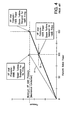
- Actual maximum output level is determined for each individual combined cycle power plant and is a function of many parameters including anticipated power demand, duct burner and HRSG limits, etc.) As shown in Figure 4, this modified steam turbine design is also operated in a sliding pressure mode, with HP inlet pressure varying linearly from zero to the maximum allowable as power output increases from 0% to the maximum 150% supplementary fired power level.
- a bypass system which redirects the steam produced by supplemental duct firing to (1) permit maximum peaking power output and (2) retain high efficiency at nominal 100% power operation.
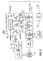
- FIGS 5 and 6 show two examples of bypass arrangements in accordance with the invention.
- Conventional combined cycle steam is produced in the HRSG, using exhaust heat from the gas turbine, and is introduced to the HP inlet. This steam is at the maximum rated pressure for the HP.
- Figure 6 shows a similar scheme as in Figure 5 wherein supplemental steam is generated in the HRSG 320 by a duct burner 364 but now bypasses the HP steam turbine section 336 altogether. Instead, the supplemental steam is now mixed with the hot reheat steam and introduced to the inlet of the IP steam turbine section 344 via streams 372 and 346 (from the drum 342), and is subsequently available to generate additional power in the IP and LP steam turbine sections 344, 348, respectively.
- actual required steam pressure may be controlled either directly in the supplemental duct firing system or by subsequent conditioning of the steam flow. As in the embodiment illustrated in Figure 5, maximum turbine efficiency is maintained at 100% operation with a small degradation in efficiency at the maximum fired condition.
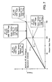
- Figure 7 shows the pressure/power relationship for a combined cycle power plant with supplemental firing and the bypass system of this invention. This Figure applies to both examples discussed above and shown in Figures 5 and 6.
- Figure 7 shows that combined cycle steam turbines equipped with the bypass system (see line C) invention can (1) be operated at maximum efficiency for the zero to 100% power range (similar to the unfired design shown in Figure 2), and (2) retain the ability to provide supplemental power using duct fired steam for peaking demand.
- Figure 7 also shows line B from Figure 4 for comparative reference.
- the invention as described above thus permits optimization of the performance of a steam turbine during unfired (non-peak output) periods, while at the same time, increasing the potential output of a given steam turbine when additional steam is admitted during fired (peak output) periods.
Landscapes
- Engineering & Computer Science (AREA)
- Chemical & Material Sciences (AREA)
- Combustion & Propulsion (AREA)
- Mechanical Engineering (AREA)
- General Engineering & Computer Science (AREA)
- Engine Equipment That Uses Special Cycles (AREA)
- Control Of Turbines (AREA)
Abstract
Description
Claims (11)
- A combined cycle power plant comprising:a gas turbine (210) driving a first generator (218);a steam turbine (230) driving a second generator (260), said steam turbine having a low pressure section (248), an intermediate pressure section (244) and a high pressure section (236);a heat recovery steam generator (220) arranged to receive exhaust gas from said gas turbine (210) and condensate from said steam turbine (238), and to utilize the exhaust gas from said gas turbine to convert condensate from said steam turbine back to steam, said heat recovery steam generator (220) having means (232, 234, 242, 246, 252, 254) for supplying steam to the high pressure, intermediate pressure and low pressure sections of the steam turbine; said heat recovery steam generator (230) further comprising a duct burner (264) for supplying supplemental steam to said steam turbine;wherein said supplemental steam is supplied to said steam turbine downstream of a high pressure inlet to said high pressure section.
- The combined cycle power plant of claim 1 wherein the supplemental steam is supplied to said high pressure section of said steam turbine, downstream of said high pressure inlet.
- The combined cycle power plant of claim 1 wherein the supplemental steam is supplied to said intermediate pressure section of said steam turbine.
- The combined cycle power plant of claim 2 wherein said supplemental steam is supplied upstream of a cold reheat steam outlet in said high pressure section.
- The combined cycle plant of claim 3 wherein said supplemental steam is mixed with hot reheat steam from a drum (342) in said heat recovery steam generator (320) prior to admission into said intermediate pressure section (344).
- A method of operating a combined cycle power plant having a gas turbine (210) driving a first generator (218); a steam turbine (238) driving a second generator (260), said steam turbine having a low pressure section (248), an intermediate pressure section (244) and a high pressure section (236); and a heat recovery steam generator (220) arranged to receive exhaust gas from the gas turbine and condensate from the steam turbine, and to utilize the exhaust gas from the gas turbine to convert condensate from the steam turbine back to steam, said heat recovery steam generator having means (232, 234, 242, 246, 252, 254) for supplying steam to the high pressure, intermediate pressure and low pressure sections of the steam turbine; the method comprising:a) providing a duct burner (264) in the heat recovery steam generator (220) for generating supplemental steam; andb) firing the duct burner and supplying the supplemental steam to said steam turbine downstream of a high pressure inlet to said high pressure section (236).
- The method of claim 5 wherein step b) is activated only in peak output periods.
- The method of claim 6 wherein the combined cycle power plant of claim 1 wherein the supplemental steam is supplied to said high pressure section of said steam turbine, downstream of said high pressure inlet.
- The method of claim 6 wherein the combined cycle power plant of claim 1 wherein the supplemental steam is supplied to said intermediate pressure section (244) of said steam turbine.
- The method of claim 7 wherein the combined cycle power plant of claim 2 wherein said supplemental steam is supplied upstream of a cold reheat steam outlet in said high pressure section (236).
- The method of claim 8 wherein the combined cycle plant of claim 3 wherein said supplemental steam is mixed with hot reheat steam from a drum (342) in said heat recovery steam generator (320) prior to admission into said intermediate pressure section (344).
Applications Claiming Priority (2)
| Application Number | Priority Date | Filing Date | Title |
|---|---|---|---|
| US09/593,277 US6442924B1 (en) | 2000-06-13 | 2000-06-13 | Optimized steam turbine peaking cycles utilizing steam bypass and related process |
| US593277 | 2000-06-13 |
Publications (3)
| Publication Number | Publication Date |
|---|---|
| EP1164254A2 true EP1164254A2 (en) | 2001-12-19 |
| EP1164254A3 EP1164254A3 (en) | 2003-08-27 |
| EP1164254B1 EP1164254B1 (en) | 2009-04-15 |
Family
ID=24374113
Family Applications (1)
| Application Number | Title | Priority Date | Filing Date |
|---|---|---|---|
| EP01305144A Expired - Lifetime EP1164254B1 (en) | 2000-06-13 | 2001-06-13 | Optimized steam turbine peaking cycles utilizing steam bypass and related process |
Country Status (4)
| Country | Link |
|---|---|
| US (1) | US6442924B1 (en) |
| EP (1) | EP1164254B1 (en) |
| JP (1) | JP2002115507A (en) |
| DE (1) | DE60138337D1 (en) |
Cited By (5)
| Publication number | Priority date | Publication date | Assignee | Title |
|---|---|---|---|---|
| WO2014056772A1 (en) * | 2012-10-11 | 2014-04-17 | Siemens Aktiengesellschaft | Method for flexibly operating a nuclear power plant |
| US8776523B2 (en) | 2010-12-01 | 2014-07-15 | General Electric Company | Steam-driven power plant |
| CN104246151A (en) * | 2011-11-14 | 2014-12-24 | 西门子公司 | Method for operating a gas and steam turbine system for frequency assistance |
| US9890709B2 (en) | 2014-11-03 | 2018-02-13 | General Electric Company | Method and system for gas turbine extraction |
| CN113586188A (en) * | 2021-09-02 | 2021-11-02 | 贵州电网有限责任公司 | Thermal power plant two-machine coordination depth peak regulation method |
Families Citing this family (26)
| Publication number | Priority date | Publication date | Assignee | Title |
|---|---|---|---|---|
| EP1757778B1 (en) * | 2005-08-23 | 2015-12-23 | Balcke-Dürr GmbH | Exhaust gas duct of a gas turbine and method for mixing the exhaust gas |
| EP2067941A3 (en) * | 2007-12-06 | 2013-06-26 | Alstom Technology Ltd | Combined cycle power plant with exhaust gas recycling and CO2 separation, and also method for operating such a combined cycle power plant |
| US20090145104A1 (en) * | 2007-12-10 | 2009-06-11 | General Electric Company | Combined cycle power plant with reserves capability |
| US8113764B2 (en) * | 2008-03-20 | 2012-02-14 | General Electric Company | Steam turbine and a method of determining leakage within a steam turbine |
| US20100077722A1 (en) * | 2008-09-30 | 2010-04-01 | General Electric Company | Peak load management by combined cycle power augmentation using peaking cycle exhaust heat recovery |
| US20100175366A1 (en) | 2009-01-09 | 2010-07-15 | General Electric Company | Ammonia injection system for peaker cycle |
| US20100180567A1 (en) * | 2009-01-16 | 2010-07-22 | General Electric Company | Combined Power Augmentation System and Method |
| US8943836B2 (en) * | 2009-07-10 | 2015-02-03 | Nrg Energy, Inc. | Combined cycle power plant |
| US8783043B2 (en) * | 2009-07-15 | 2014-07-22 | Siemens Aktiengesellschaft | Method for removal of entrained gas in a combined cycle power generation system |
| US8387356B2 (en) * | 2009-11-02 | 2013-03-05 | General Electric Company | Method of increasing power output of a combined cycle power plant during select operating periods |
| JP5597016B2 (en) | 2010-04-07 | 2014-10-01 | 株式会社東芝 | Steam turbine plant |
| JP5479192B2 (en) | 2010-04-07 | 2014-04-23 | 株式会社東芝 | Steam turbine plant |
| JP5479191B2 (en) | 2010-04-07 | 2014-04-23 | 株式会社東芝 | Steam turbine plant |
| EP2644848A1 (en) | 2012-03-29 | 2013-10-02 | Alstom Technology Ltd | Method for operating a combined cycle power plant and combined cycle power plant for conducting said method |
| US20140033676A1 (en) * | 2012-08-02 | 2014-02-06 | Raymond Pang | Unique method of solar integration in combined cycle power plant |
| US9322295B2 (en) | 2012-10-17 | 2016-04-26 | General Electric Company | Thermal energy storage unit with steam and gas turbine system |
| US9376962B2 (en) * | 2012-12-14 | 2016-06-28 | General Electric Company | Fuel gas heating with thermal energy storage |
| FI127597B (en) * | 2013-03-05 | 2018-09-28 | Loeytty Ari Veli Olavi | Method and apparatus for achieving high efficiency in the open gas turbine (combi) process |
| US9771824B2 (en) | 2015-09-22 | 2017-09-26 | General Electric Company | Method and system for an electric and steam supply system |
| DE102016218763A1 (en) * | 2016-09-28 | 2018-03-29 | Siemens Aktiengesellschaft | Method for short-term power adaptation of a steam turbine of a gas and steam power plant for primary control |
| CN108104888B (en) * | 2017-12-28 | 2023-09-05 | 赫普能源环境科技股份有限公司 | Power grid frequency modulation system and method based on frequency modulation bypass |
| CA3089431A1 (en) * | 2018-01-29 | 2019-08-01 | Single Buoy Moorings Inc. | Offshore electrical power plant |
| KR102382058B1 (en) * | 2020-10-30 | 2022-04-04 | 두산중공업 주식회사 | Hybrid power generation equipment and control method thereof |
| FI131342B1 (en) * | 2021-11-10 | 2025-02-28 | Loeytty Ari Veli Olavi | Method and apparatus for reducing energy losses in gas turbine combined cycle plants |
| US11988114B2 (en) | 2022-04-21 | 2024-05-21 | Mitsubishi Power Americas, Inc. | H2 boiler for steam system |
| CN115523000B (en) * | 2022-10-19 | 2024-05-14 | 峰和轻碳(北京)设计研究院有限公司 | Thermal power peak regulation energy-saving system and regulation method of small pre-regulation stage steam turbine |
Family Cites Families (9)
| Publication number | Priority date | Publication date | Assignee | Title |
|---|---|---|---|---|
| US3879616A (en) | 1973-09-17 | 1975-04-22 | Gen Electric | Combined steam turbine and gas turbine power plant control system |
| US4207864A (en) | 1978-06-08 | 1980-06-17 | General Electric Company | Damper |
| US4329592A (en) | 1980-09-15 | 1982-05-11 | General Electric Company | Steam turbine control |
| US5375410A (en) * | 1993-01-25 | 1994-12-27 | Westinghouse Electric Corp. | Combined combustion and steam turbine power plant |
| USRE36524E (en) | 1993-11-04 | 2000-01-25 | General Electric Co. | Steam attemperation circuit for a combined cycle steam cooled gas turbine |
| USRE36497E (en) | 1993-11-04 | 2000-01-18 | General Electric Co. | Combined cycle with steam cooled gas turbine |
| US5628179A (en) | 1993-11-04 | 1997-05-13 | General Electric Co. | Steam attemperation circuit for a combined cycle steam cooled gas turbine |
| CA2144617C (en) | 1995-03-14 | 2001-06-05 | Louie Leonelli | Two piece window frame generated from a single extrusion |
| US6230480B1 (en) * | 1998-08-31 | 2001-05-15 | Rollins, Iii William Scott | High power density combined cycle power plant |
-
2000
- 2000-06-13 US US09/593,277 patent/US6442924B1/en not_active Expired - Fee Related
-
2001
- 2001-06-12 JP JP2001176398A patent/JP2002115507A/en active Pending
- 2001-06-13 EP EP01305144A patent/EP1164254B1/en not_active Expired - Lifetime
- 2001-06-13 DE DE60138337T patent/DE60138337D1/en not_active Expired - Lifetime
Cited By (8)
| Publication number | Priority date | Publication date | Assignee | Title |
|---|---|---|---|---|
| US8776523B2 (en) | 2010-12-01 | 2014-07-15 | General Electric Company | Steam-driven power plant |
| CN104246151A (en) * | 2011-11-14 | 2014-12-24 | 西门子公司 | Method for operating a gas and steam turbine system for frequency assistance |
| CN104246151B (en) * | 2011-11-14 | 2016-07-13 | 西门子公司 | For the method that frequency remains on combustion gas and steam turbine |
| WO2014056772A1 (en) * | 2012-10-11 | 2014-04-17 | Siemens Aktiengesellschaft | Method for flexibly operating a nuclear power plant |
| US10487696B2 (en) | 2012-10-11 | 2019-11-26 | Siemens Aktiengesellschaft | Method for the flexible operation of a power plant |
| US9890709B2 (en) | 2014-11-03 | 2018-02-13 | General Electric Company | Method and system for gas turbine extraction |
| CN113586188A (en) * | 2021-09-02 | 2021-11-02 | 贵州电网有限责任公司 | Thermal power plant two-machine coordination depth peak regulation method |
| CN113586188B (en) * | 2021-09-02 | 2024-04-26 | 贵州电网有限责任公司 | Method for coordinating deep peak regulation of two machines of thermal power plant |
Also Published As
| Publication number | Publication date |
|---|---|
| EP1164254A3 (en) | 2003-08-27 |
| JP2002115507A (en) | 2002-04-19 |
| EP1164254B1 (en) | 2009-04-15 |
| DE60138337D1 (en) | 2009-05-28 |
| US6442924B1 (en) | 2002-09-03 |
Similar Documents
| Publication | Publication Date | Title |
|---|---|---|
| US6442924B1 (en) | Optimized steam turbine peaking cycles utilizing steam bypass and related process | |
| US6945052B2 (en) | Methods and apparatus for starting up emission-free gas-turbine power stations | |
| EP1186761B1 (en) | Energy recovery from compressor discharge bleed air in gas turbine plants | |
| RU2506440C2 (en) | Device for starting steam turbine at rated pressure | |
| JP3162479B2 (en) | Gas / steam combined power plant | |
| US5267434A (en) | Gas turbine topped steam plant | |
| KR101009852B1 (en) | Waste heat steam generator | |
| EP3098400B1 (en) | Method for enhanced cold steam turbine start in a supplementary fired multi gas turbine combined cycle plant | |
| US20010039797A1 (en) | Advanced Cheng combined cycle | |
| WO1995011376A1 (en) | Performance enhanced gas turbine powerplants | |
| CA2114072A1 (en) | Combined combustion and steam turbine power plant | |
| JP2013545915A (en) | Method for operating a combined cycle power plant for cogeneration and a combined cycle power plant for implementing the method | |
| CN103154445B (en) | Method for operating combined-cycle power plant with cogeneration and combined-cycle power plant for carrying out the method | |
| CA2179867A1 (en) | Method and apparatus of conversion of a reheat steam turbine power plant to a non-reheat combined cycle power plant | |
| CN104246151A (en) | Method for operating a gas and steam turbine system for frequency assistance | |
| JP4036914B2 (en) | Power plant operation | |
| JP3925985B2 (en) | Combined cycle power plant | |
| GB2453849A (en) | Steam power plant with additional bypass pipe used to control power output | |
| JP7808700B2 (en) | Oxyfuel turbine system and oxidizer control method | |
| WO1994008128A1 (en) | Cheng dual fluid regenerative cycle | |
| JP3518252B2 (en) | Closed steam cooled gas turbine combined plant and gas turbine combined plant | |
| Casper | Application of the LM6000 for Power Generation and Cogeneration | |
| JP4090584B2 (en) | Combined cycle power plant | |
| JPH09166002A (en) | Combined cycle power plant | |
| Caputo et al. | Internal Combustion Steam Cycle (GIST Cycle): Thermodynamical Feasibility and Plant Lay-Out Proposals |
Legal Events
| Date | Code | Title | Description |
|---|---|---|---|
| PUAI | Public reference made under article 153(3) epc to a published international application that has entered the european phase |
Free format text: ORIGINAL CODE: 0009012 |
|
| AK | Designated contracting states |
Kind code of ref document: A2 Designated state(s): AT BE CH CY DE DK ES FI FR GB GR IE IT LI LU MC NL PT SE TR |
|
| AX | Request for extension of the european patent |
Free format text: AL;LT;LV;MK;RO;SI |
|
| PUAL | Search report despatched |
Free format text: ORIGINAL CODE: 0009013 |
|
| AK | Designated contracting states |
Designated state(s): AT BE CH CY DE DK ES FI FR GB GR IE IT LI LU MC NL PT SE TR |
|
| AX | Request for extension of the european patent |
Extension state: AL LT LV MK RO SI |
|
| 17P | Request for examination filed |
Effective date: 20040227 |
|
| AKX | Designation fees paid |
Designated state(s): CH DE FI GB IT LI |
|
| 17Q | First examination report despatched |
Effective date: 20080225 |
|
| GRAP | Despatch of communication of intention to grant a patent |
Free format text: ORIGINAL CODE: EPIDOSNIGR1 |
|
| GRAP | Despatch of communication of intention to grant a patent |
Free format text: ORIGINAL CODE: EPIDOSNIGR1 |
|
| GRAS | Grant fee paid |
Free format text: ORIGINAL CODE: EPIDOSNIGR3 |
|
| GRAA | (expected) grant |
Free format text: ORIGINAL CODE: 0009210 |
|
| AK | Designated contracting states |
Kind code of ref document: B1 Designated state(s): CH DE FI GB IT LI |
|
| REG | Reference to a national code |
Ref country code: GB Ref legal event code: FG4D Ref country code: CH Ref legal event code: EP |
|
| REG | Reference to a national code |
Ref country code: CH Ref legal event code: NV Representative=s name: SERVOPATENT GMBH |
|
| REF | Corresponds to: |
Ref document number: 60138337 Country of ref document: DE Date of ref document: 20090528 Kind code of ref document: P |
|
| PLBE | No opposition filed within time limit |
Free format text: ORIGINAL CODE: 0009261 |
|
| STAA | Information on the status of an ep patent application or granted ep patent |
Free format text: STATUS: NO OPPOSITION FILED WITHIN TIME LIMIT |
|
| 26N | No opposition filed |
Effective date: 20100118 |
|
| PGFP | Annual fee paid to national office [announced via postgrant information from national office to epo] |
Ref country code: FI Payment date: 20100629 Year of fee payment: 10 |
|
| PGFP | Annual fee paid to national office [announced via postgrant information from national office to epo] |
Ref country code: IT Payment date: 20100624 Year of fee payment: 10 |
|
| PGFP | Annual fee paid to national office [announced via postgrant information from national office to epo] |
Ref country code: CH Payment date: 20100625 Year of fee payment: 10 |
|
| PGFP | Annual fee paid to national office [announced via postgrant information from national office to epo] |
Ref country code: DE Payment date: 20100629 Year of fee payment: 10 Ref country code: GB Payment date: 20100625 Year of fee payment: 10 |
|
| PG25 | Lapsed in a contracting state [announced via postgrant information from national office to epo] |
Ref country code: FI Free format text: LAPSE BECAUSE OF NON-PAYMENT OF DUE FEES Effective date: 20110613 |
|
| REG | Reference to a national code |
Ref country code: CH Ref legal event code: PL |
|
| GBPC | Gb: european patent ceased through non-payment of renewal fee |
Effective date: 20110613 |
|
| PG25 | Lapsed in a contracting state [announced via postgrant information from national office to epo] |
Ref country code: IT Free format text: LAPSE BECAUSE OF NON-PAYMENT OF DUE FEES Effective date: 20110613 |
|
| REG | Reference to a national code |
Ref country code: DE Ref legal event code: R119 Ref document number: 60138337 Country of ref document: DE Effective date: 20120103 |
|
| PG25 | Lapsed in a contracting state [announced via postgrant information from national office to epo] |
Ref country code: LI Free format text: LAPSE BECAUSE OF NON-PAYMENT OF DUE FEES Effective date: 20110630 Ref country code: CH Free format text: LAPSE BECAUSE OF NON-PAYMENT OF DUE FEES Effective date: 20110630 Ref country code: DE Free format text: LAPSE BECAUSE OF NON-PAYMENT OF DUE FEES Effective date: 20120103 |
|
| PG25 | Lapsed in a contracting state [announced via postgrant information from national office to epo] |
Ref country code: GB Free format text: LAPSE BECAUSE OF NON-PAYMENT OF DUE FEES Effective date: 20110613 |