EP1163094B1 - Mixed articles comprising a rigid part and a part based on a thermoplastic material, and manufacturing method - Google Patents
Mixed articles comprising a rigid part and a part based on a thermoplastic material, and manufacturing method Download PDFInfo
- Publication number
- EP1163094B1 EP1163094B1 EP00911016A EP00911016A EP1163094B1 EP 1163094 B1 EP1163094 B1 EP 1163094B1 EP 00911016 A EP00911016 A EP 00911016A EP 00911016 A EP00911016 A EP 00911016A EP 1163094 B1 EP1163094 B1 EP 1163094B1
- Authority
- EP
- European Patent Office
- Prior art keywords
- thermoplastic material
- rigid element
- article according
- concave space
- section
- Prior art date
- Legal status (The legal status is an assumption and is not a legal conclusion. Google has not performed a legal analysis and makes no representation as to the accuracy of the status listed.)
- Expired - Lifetime
Links
Images


Classifications
-
- B—PERFORMING OPERATIONS; TRANSPORTING
- B62—LAND VEHICLES FOR TRAVELLING OTHERWISE THAN ON RAILS
- B62D—MOTOR VEHICLES; TRAILERS
- B62D29/00—Superstructures, understructures, or sub-units thereof, characterised by the material thereof
- B62D29/001—Superstructures, understructures, or sub-units thereof, characterised by the material thereof characterised by combining metal and synthetic material
-
- B—PERFORMING OPERATIONS; TRANSPORTING
- B29—WORKING OF PLASTICS; WORKING OF SUBSTANCES IN A PLASTIC STATE IN GENERAL
- B29C—SHAPING OR JOINING OF PLASTICS; SHAPING OF MATERIAL IN A PLASTIC STATE, NOT OTHERWISE PROVIDED FOR; AFTER-TREATMENT OF THE SHAPED PRODUCTS, e.g. REPAIRING
- B29C45/00—Injection moulding, i.e. forcing the required volume of moulding material through a nozzle into a closed mould; Apparatus therefor
- B29C45/14—Injection moulding, i.e. forcing the required volume of moulding material through a nozzle into a closed mould; Apparatus therefor incorporating preformed parts or layers, e.g. injection moulding around inserts or for coating articles
- B29C45/14336—Coating a portion of the article, e.g. the edge of the article
-
- B—PERFORMING OPERATIONS; TRANSPORTING
- B29—WORKING OF PLASTICS; WORKING OF SUBSTANCES IN A PLASTIC STATE IN GENERAL
- B29C—SHAPING OR JOINING OF PLASTICS; SHAPING OF MATERIAL IN A PLASTIC STATE, NOT OTHERWISE PROVIDED FOR; AFTER-TREATMENT OF THE SHAPED PRODUCTS, e.g. REPAIRING
- B29C45/00—Injection moulding, i.e. forcing the required volume of moulding material through a nozzle into a closed mould; Apparatus therefor
- B29C45/17—Component parts, details or accessories; Auxiliary operations
- B29C45/1703—Introducing an auxiliary fluid into the mould
- B29C45/1704—Introducing an auxiliary fluid into the mould the fluid being introduced into the interior of the injected material which is still in a molten state, e.g. for producing hollow articles
- B29C45/1706—Introducing an auxiliary fluid into the mould the fluid being introduced into the interior of the injected material which is still in a molten state, e.g. for producing hollow articles using particular fluids or fluid generating substances
-
- B—PERFORMING OPERATIONS; TRANSPORTING
- B62—LAND VEHICLES FOR TRAVELLING OTHERWISE THAN ON RAILS
- B62D—MOTOR VEHICLES; TRAILERS
- B62D29/00—Superstructures, understructures, or sub-units thereof, characterised by the material thereof
- B62D29/001—Superstructures, understructures, or sub-units thereof, characterised by the material thereof characterised by combining metal and synthetic material
- B62D29/004—Superstructures, understructures, or sub-units thereof, characterised by the material thereof characterised by combining metal and synthetic material the metal being over-moulded by the synthetic material, e.g. in a mould
-
- B—PERFORMING OPERATIONS; TRANSPORTING
- B62—LAND VEHICLES FOR TRAVELLING OTHERWISE THAN ON RAILS
- B62D—MOTOR VEHICLES; TRAILERS
- B62D29/00—Superstructures, understructures, or sub-units thereof, characterised by the material thereof
- B62D29/001—Superstructures, understructures, or sub-units thereof, characterised by the material thereof characterised by combining metal and synthetic material
- B62D29/005—Superstructures, understructures, or sub-units thereof, characterised by the material thereof characterised by combining metal and synthetic material preformed metal and synthetic material elements being joined together, e.g. by adhesives
-
- F—MECHANICAL ENGINEERING; LIGHTING; HEATING; WEAPONS; BLASTING
- F28—HEAT EXCHANGE IN GENERAL
- F28F—DETAILS OF HEAT-EXCHANGE AND HEAT-TRANSFER APPARATUS, OF GENERAL APPLICATION
- F28F1/00—Tubular elements; Assemblies of tubular elements
-
- F—MECHANICAL ENGINEERING; LIGHTING; HEATING; WEAPONS; BLASTING
- F28—HEAT EXCHANGE IN GENERAL
- F28F—DETAILS OF HEAT-EXCHANGE AND HEAT-TRANSFER APPARATUS, OF GENERAL APPLICATION
- F28F21/00—Constructions of heat-exchange apparatus characterised by the selection of particular materials
- F28F21/06—Constructions of heat-exchange apparatus characterised by the selection of particular materials of plastics material
- F28F21/062—Constructions of heat-exchange apparatus characterised by the selection of particular materials of plastics material the heat-exchange apparatus employing tubular conduits
-
- B—PERFORMING OPERATIONS; TRANSPORTING
- B29—WORKING OF PLASTICS; WORKING OF SUBSTANCES IN A PLASTIC STATE IN GENERAL
- B29C—SHAPING OR JOINING OF PLASTICS; SHAPING OF MATERIAL IN A PLASTIC STATE, NOT OTHERWISE PROVIDED FOR; AFTER-TREATMENT OF THE SHAPED PRODUCTS, e.g. REPAIRING
- B29C45/00—Injection moulding, i.e. forcing the required volume of moulding material through a nozzle into a closed mould; Apparatus therefor
- B29C45/17—Component parts, details or accessories; Auxiliary operations
- B29C45/1703—Introducing an auxiliary fluid into the mould
- B29C45/1704—Introducing an auxiliary fluid into the mould the fluid being introduced into the interior of the injected material which is still in a molten state, e.g. for producing hollow articles
- B29C45/1706—Introducing an auxiliary fluid into the mould the fluid being introduced into the interior of the injected material which is still in a molten state, e.g. for producing hollow articles using particular fluids or fluid generating substances
- B29C2045/1707—Introducing an auxiliary fluid into the mould the fluid being introduced into the interior of the injected material which is still in a molten state, e.g. for producing hollow articles using particular fluids or fluid generating substances using a liquid, e.g. water
-
- B—PERFORMING OPERATIONS; TRANSPORTING
- B29—WORKING OF PLASTICS; WORKING OF SUBSTANCES IN A PLASTIC STATE IN GENERAL
- B29C—SHAPING OR JOINING OF PLASTICS; SHAPING OF MATERIAL IN A PLASTIC STATE, NOT OTHERWISE PROVIDED FOR; AFTER-TREATMENT OF THE SHAPED PRODUCTS, e.g. REPAIRING
- B29C45/00—Injection moulding, i.e. forcing the required volume of moulding material through a nozzle into a closed mould; Apparatus therefor
- B29C45/17—Component parts, details or accessories; Auxiliary operations
- B29C45/1703—Introducing an auxiliary fluid into the mould
- B29C45/1704—Introducing an auxiliary fluid into the mould the fluid being introduced into the interior of the injected material which is still in a molten state, e.g. for producing hollow articles
- B29C2045/1724—Introducing an auxiliary fluid into the mould the fluid being introduced into the interior of the injected material which is still in a molten state, e.g. for producing hollow articles hollows used as conduits
-
- B—PERFORMING OPERATIONS; TRANSPORTING
- B29—WORKING OF PLASTICS; WORKING OF SUBSTANCES IN A PLASTIC STATE IN GENERAL
- B29K—INDEXING SCHEME ASSOCIATED WITH SUBCLASSES B29B, B29C OR B29D, RELATING TO MOULDING MATERIALS OR TO MATERIALS FOR MOULDS, REINFORCEMENTS, FILLERS OR PREFORMED PARTS, e.g. INSERTS
- B29K2077/00—Use of PA, i.e. polyamides, e.g. polyesteramides or derivatives thereof, as moulding material
-
- B—PERFORMING OPERATIONS; TRANSPORTING
- B29—WORKING OF PLASTICS; WORKING OF SUBSTANCES IN A PLASTIC STATE IN GENERAL
- B29L—INDEXING SCHEME ASSOCIATED WITH SUBCLASS B29C, RELATING TO PARTICULAR ARTICLES
- B29L2031/00—Other particular articles
- B29L2031/18—Heat-exchangers or parts thereof
-
- B—PERFORMING OPERATIONS; TRANSPORTING
- B29—WORKING OF PLASTICS; WORKING OF SUBSTANCES IN A PLASTIC STATE IN GENERAL
- B29L—INDEXING SCHEME ASSOCIATED WITH SUBCLASS B29C, RELATING TO PARTICULAR ARTICLES
- B29L2031/00—Other particular articles
- B29L2031/30—Vehicles, e.g. ships or aircraft, or body parts thereof
- B29L2031/3002—Superstructures characterized by combining metal and plastics, i.e. hybrid parts
-
- B—PERFORMING OPERATIONS; TRANSPORTING
- B29—WORKING OF PLASTICS; WORKING OF SUBSTANCES IN A PLASTIC STATE IN GENERAL
- B29L—INDEXING SCHEME ASSOCIATED WITH SUBCLASS B29C, RELATING TO PARTICULAR ARTICLES
- B29L2031/00—Other particular articles
- B29L2031/30—Vehicles, e.g. ships or aircraft, or body parts thereof
- B29L2031/3005—Body finishings
-
- B—PERFORMING OPERATIONS; TRANSPORTING
- B29—WORKING OF PLASTICS; WORKING OF SUBSTANCES IN A PLASTIC STATE IN GENERAL
- B29L—INDEXING SCHEME ASSOCIATED WITH SUBCLASS B29C, RELATING TO PARTICULAR ARTICLES
- B29L2031/00—Other particular articles
- B29L2031/30—Vehicles, e.g. ships or aircraft, or body parts thereof
- B29L2031/3055—Cars
-
- Y—GENERAL TAGGING OF NEW TECHNOLOGICAL DEVELOPMENTS; GENERAL TAGGING OF CROSS-SECTIONAL TECHNOLOGIES SPANNING OVER SEVERAL SECTIONS OF THE IPC; TECHNICAL SUBJECTS COVERED BY FORMER USPC CROSS-REFERENCE ART COLLECTIONS [XRACs] AND DIGESTS
- Y10—TECHNICAL SUBJECTS COVERED BY FORMER USPC
- Y10T—TECHNICAL SUBJECTS COVERED BY FORMER US CLASSIFICATION
- Y10T428/00—Stock material or miscellaneous articles
- Y10T428/13—Hollow or container type article [e.g., tube, vase, etc.]
- Y10T428/1352—Polymer or resin containing [i.e., natural or synthetic]
-
- Y—GENERAL TAGGING OF NEW TECHNOLOGICAL DEVELOPMENTS; GENERAL TAGGING OF CROSS-SECTIONAL TECHNOLOGIES SPANNING OVER SEVERAL SECTIONS OF THE IPC; TECHNICAL SUBJECTS COVERED BY FORMER USPC CROSS-REFERENCE ART COLLECTIONS [XRACs] AND DIGESTS
- Y10—TECHNICAL SUBJECTS COVERED BY FORMER USPC
- Y10T—TECHNICAL SUBJECTS COVERED BY FORMER US CLASSIFICATION
- Y10T428/00—Stock material or miscellaneous articles
- Y10T428/22—Nonparticulate element embedded or inlaid in substrate and visible
Landscapes
- Engineering & Computer Science (AREA)
- Mechanical Engineering (AREA)
- Manufacturing & Machinery (AREA)
- Architecture (AREA)
- Structural Engineering (AREA)
- Chemical & Material Sciences (AREA)
- Combustion & Propulsion (AREA)
- Transportation (AREA)
- Physics & Mathematics (AREA)
- Thermal Sciences (AREA)
- General Engineering & Computer Science (AREA)
- Injection Moulding Of Plastics Or The Like (AREA)
- Laminated Bodies (AREA)
- Materials For Medical Uses (AREA)
- Toys (AREA)
- Casting Or Compression Moulding Of Plastics Or The Like (AREA)
Abstract
Description
La présente invention concerne la réalisation d'articles comportant au moins un élément rigide et au moins un élément constitué de matière thermoplastique obtenu par moulage.The present invention relates to the production of articles comprising at least one rigid element and at least one element made of thermoplastic material obtained by molding.
Dans les domaines industriels concernant la fabrication d'objets manufacturés, par exemple dans les domaines du bâtiment, de l'ameublement, de l'automobile et des biens de consommation, les articles réalisés doivent de manière générale être légers et présenter les propriétés nécessaires à l'usage, notamment des propriétés mécaniques suffisamment élevées. Pour répondre à ces spécifications, le choix des matériaux et la forme conférée à ceux-ci sont déterminants.In the industrial fields concerning the manufacture of manufactured objects, for example example in the fields of construction, furniture, automobile and goods consumption, the articles produced must generally be light and present the properties necessary for use, in particular mechanical properties sufficiently high. To meet these specifications, the choice of materials and the form given to these are decisive.
Les dernières décennies ont vu se développer l'utilisation des matières plastiques, par exemple dans les domaines de l'automobile ou de la construction, qui sont plus légères et qui peuvent être plus facilement travaillées que les métaux. Il est ainsi possible de fabriquer des articles légers présentant des formes complexes, par exemple par injection dans un moule d'un polymère fondu.The last decades have seen the development of the use of plastics, for example in the automotive or construction fields, which are more light and can be worked more easily than metals. It is thus possible to manufacture light articles with complex shapes, for example by injection into a mold of a molten polymer.
Toutefois l'utilisation de matières plastiques peut être limitée dans certains domaines. La réalisation de grandes pièces peut par exemple poser des problèmes de stabilité dimensionnelle, en particulier dans les applications où elles sont soumises à des variations de température ou à des vibrations. C'est le cas notamment dans le domaine de l'automobile pour certaines pièces situées sous le capot. D'autre part, les pièces réalisées en matière plastique peuvent présenter des propriétés mécaniques insuffisantes pour l'application considérée.However the use of plastics may be limited in certain areas. The production of large parts can for example pose problems of dimensional stability, especially in applications where they are subjected to variations in temperature or vibration. This is particularly the case in the field of the automobile for certain parts located under the hood. On the other hand, the pieces made of plastic can have mechanical properties insufficient for the application considered.
Afin de surmonter ce type de difficultés il est connu d'associer différents matériaux, par exemple des éléments métalliques et des éléments constitués de matière thermoplastique. Il existe de très nombreuses publications concernant des structures pouvant être adoptées pour adapter des pièces comportant des matières plastiques et des éléments additionnels adaptés à l'usage auquel elles sont destinées. A titre d'exemple on peut citer la demande de brevet publiée DE4334049 qui enseigne d'insérer des pièces métalliques dans des plaques de matière plastique, la demande de brevet publiée DE4330273 qui enseigne de renforcer des cadres de fenêtres en plastique avec des tiges profilées métalliques. La demande de brevet publiée EP370342 enseigne de renforcer une structure métallique de profil en forme de U avec des nervures en matière thermoplastique injectée à l'intérieur de la structure métallique. In order to overcome this type of difficulty, it is known to combine different materials, for example metallic elements and elements made of material thermoplastic. There are very many publications concerning structures which can be adopted to adapt parts comprising plastic materials and additional elements adapted to the use for which they are intended. As example we can cite the published patent application DE4334049 which teaches to insert metal parts in plastic sheets, patent application published DE4330273 which teaches to reinforce plastic window frames with profiled metal rods. The published patent application EP370342 teaches reinforce a U-shaped profile metal structure with material ribs thermoplastic injected inside the metal structure.
La présente invention a pour objectif de proposer de nouveaux articles dans lesquels sont associés au moins un élément constitué de matière thermoplastique et un élément rigide, par exemple métallique, les articles selon cette structure présentant notamment une bonne stabilité dimensionnelle et une intégrité au choc.The object of the present invention is to propose new articles in which are associated with at least one element made of thermoplastic material and one rigid element, for example metallic, the articles according to this structure having in particular good dimensional stability and impact integrity.
A cet effet l'invention propose un article comportant une partie constituée d'un élément rigide de forme allongée dont au moins une partie présente une section transversale ayant un profil définissant un espace concave, et comportant au moins une partie en matière thermoplastique associée à l'élément rigide et positionnée dans l'espace concave, caractérisé en ce que la partie en matière thermoplastique est en contact sur au moins deux lignes continues dans la direction longitudianle, et en ce que la partie en matière thermoplastique présente une section transversale comportant au moins un creux.To this end the invention provides an article comprising a part consisting of a rigid elongated element at least part of which has a cross section transverse having a profile defining a concave space, and comprising at least one part in thermoplastic material associated with the rigid element and positioned in the concave space, characterized in that the part made of thermoplastic material is contact on at least two continuous lines in the longitudinal direction, and in that the part made of thermoplastic material has a cross section comprising at minus a trough.
La partie en matière thermoplastique peut être utilisé comme renfort d'un élément rigide léger, par exemple pour la réalisation d'éléments de construction. Ces éléments de construction sont généralement de forme allongée droite ou courbe, en forme de coque ou tubulaires, constitués d'un ou plusieurs segments. Comme exemples de tels articles on peut citer les poutres ou les longerons. Les domaines d'application préférés pour ce type d'articles sont le bâtiment, l'ameublement, la construction automobile, pour la réalisation de pièces structurelles destinées à supporter d'autres pièces. Les articles renforcés de la sorte présentent l'avantage d'être légers tout en conservant des propriétés mécaniques suffisantes par exemple pour supporter d'autres structures. En particulier, l'élément rigide permet une répartition des efforts sur la totalité de l'article et la partie en matière thermoplastique permet de renforcer l'article.The part in thermoplastic material can be used as reinforcement of an element rigid light, for example for the construction of building elements. These elements of construction are generally elongated straight or curved, shell-shaped or tubular, made up of one or more segments. As examples of such articles we can cite beams or beams. Preferred areas of application for this type of items are building, furnishing, automobile construction, for the production of structural parts intended to support other parts. The articles reinforced in this way have the advantage of being light while retaining sufficient mechanical properties for example to support other structures. In particular, the rigid element allows a distribution of forces over the entire article and the part in thermoplastic material to strengthen the article.
La partie de l'article en matière thermoplastique peut présenter de nombreuses fonctionnalités, l'élément rigide servant de renfort ou de stabilisateur de la forme en matière thermoplastique. La partie en matière thermoplastique peut présenter une structure très complexe, avec par exemple des espaces pour loger d'autres pièces, des nervures de renfort, des moyen d'assemblage avec d'autres pièces ou systèmes, par exemple des clips. L'élément rigide peut être totalement intégré dans la structure définie par la partie en matière thermoplastique, être apparent ou complètement inséré dans la matière thermoplastique. Il peut être utilisé comme simple élément structurel de renfort ou présenter des fonctionnalités propres. Il peut par exemple présenter des moyens d'assemblage à d'autres pièces. De telles structures présentent une stabilité dimensionnelle supérieure à celle de structures réalisées uniquement à partir de matières thermoplastiques. Les variations de dimension des parties en matière plastiques sont en effet limitées par celles de l'élément rigide avec lequel elles sont en contact. Il est ainsi possible de réaliser de grandes pièces à base de matière thermoplastique. Un autre avantage de telles structures est l'amélioration de l'intégrité au choc, c'est à dire la capacité d'un objet à ne pas être fractionné en plusieurs parties après un choc. Les articles selon ce mode de réalisation sont donc notamment adaptés à la réalisation de pièces pour l'automobile, par exemple pour la réalisation de faces avant.The part of the article made of thermoplastic material may have many functionalities, the rigid element serving as reinforcement or stabilizer of the shape in thermoplastic material. The thermoplastic part may have a very complex structure, with for example spaces to accommodate other rooms, reinforcing ribs, means of assembly with other parts or systems, by example of clips. The rigid element can be fully integrated into the defined structure by the thermoplastic part, be visible or completely inserted in the thermoplastic material. It can be used as a simple structural reinforcement element or present their own functionalities. It can for example present means assembly to other parts. Such structures exhibit stability larger than that of structures made only from materials thermoplastics. The variations in size of the plastic parts are in effect limited by those of the rigid element with which they are in contact. It is so large parts made from thermoplastic material can be made. Another advantage of such structures is the improvement of impact integrity, i.e. the ability of an object not to be divided into several parts after a shock. The articles according to this embodiment are therefore particularly suitable for the realization of parts for the automobile, for example for the production of front panels.
Les articles selon l'invention peuvent être utilisés tels quels en tant que biens de consommation ou être associés à d'autres pièce, éléments ou systèmes, par exemple par collage soudure, rivetage, encastrement ou clipsage.The articles according to the invention can be used as such as goods for consumption or be associated with other parts, elements or systems, for example by welding bonding, riveting, embedding or clipping.
L'article selon l'invention peut comporter une ou plusieurs parties en matière thermoplastique et dont la section transversale comporte au moins un creux. Dans le cas où il en comporte plusieurs, les parties en matière thermoplastique peuvent être matériellement séparées ou faire partie d'un seul élément matériel en matière thermoplastique. Ainsi deux parties en matières thermoplastique de section creuse positionnées dans l'espace concave peuvent par exemple être liées entre elles par une base en matière thermoplastique. Les moyens de liaisons peuvent est compris à l'intérieur ou à l'extérieur de l'espace concave de l'élément rigide. Les éléments en matière thermoplastique sont généralement mis en forme par moulage.The article according to the invention may include one or more parts relating to thermoplastic and whose cross section has at least one hollow. In the case where there are several, the thermoplastic parts can be materially separate or be part of a single material element in matters thermoplastic. Thus two parts in thermoplastic material of hollow section positioned in the concave space can for example be linked together by a base in thermoplastic material. The means of connection can be understood at inside or outside the concave space of the rigid element. The elements in thermoplastic material are generally shaped by molding.
L'élément rigide présente une forme allongée, droite ou courbe. Il peut également comporter plusieurs tronçons sensiblement allongés et séparés par exemple par des coudes ou des changements de courbures. On peut définir pour ces formes une section transversale perpendiculaire à la direction longitudinale. L'élément rigide et la partie en matière thermoplastique sont en contact sur au moins deux lignes continues dans la direction longitudinale. Les lignes de contacts peuvent être droites, ou courbes, parallèles à la direction longitudinale, ou obliques par rapport à cette direction. Par contact sur au moins deux lignes, on entend que pour toute section transversale, l'étément rigide et la partie en matière thermoplastique sont en contact en au moins deux points du profil définissant l'espace concave. L'élément rigide et la partie en matière thermoplastique sont de préférence en contact sur des surfaces continues.The rigid element has an elongated, straight or curved shape. He can also have several substantially elongated sections separated for example by elbows or changes in curvature. We can define for these forms a section transverse perpendicular to the longitudinal direction. The rigid element and the part in thermoplastic material are in contact on at least two continuous lines in the longitudinal direction. Contact lines can be straight, or curved, parallel to the longitudinal direction, or oblique to this direction. By contact on at minus two lines, we mean that for any cross section, the rigid element and the part in thermoplastic material are in contact at at least two points of the profile defining the concave space. The rigid element and the part in thermoplastic material are preferably in contact on continuous surfaces.
La partie en matière thermoplastique et l'élément rigide sont avantageusement en contact sur la totalité du profil ou sur des portions du profil, de préférence sur aux moins deux portions. La partie en matière thermoplastique peut par exemple prendre appui l'élément rigide en des bandes de contact continues.The part made of thermoplastic material and the rigid element are advantageously made of contact over the entire profile or over portions of the profile, preferably at least two servings. The part in thermoplastic material can for example bear the rigid element in continuous contact strips.
La partie en matière thermoplastique positionnée dans l'espace concave de l'élément rigide est creuse, c'est-à-dire qu'elle présente, sur au moins une partie, une section transversale présentant un espace qui est totalement entouré de matière thermoplastique. The part in thermoplastic material positioned in the concave space of the rigid element is hollow, that is to say that it has, on at least part, a cross section with a space that is completely surrounded by material thermoplastic.
Selon un premier mode de réalisation de l'invention, l'article comporte une partie en matière thermoplastique présentant un profil conjugué à l'espace concave défini par le profil de rélément rigide. Selon ce mode de réalisation, la partie en matière thermoplastique comble l'espace concave totalement ou en grande partie, la partie en matière thermoplastique et l'élément rigide étant en contact sur la totalité ou sur une grande partie de la section.According to a first embodiment of the invention, the article comprises a part in thermoplastic material having a profile combined with the concave space defined by the rigid element profile. According to this embodiment, the part in thermoplastic fills the concave space totally or largely, the part in thermoplastic material and the rigid element being in contact over the whole or over a much of the section.
Pour ce premier mode de réalisation, les éléments rigides comportent par exemple une partie en forme de U, de V, de demi-cercles, présentant éventuellement des méplats. Les éléments rigides peuvent également présenter une section transversale fermée. Par section transversale fermée, il faut entendre toute forme géométrique pour laquelle il est possible de définir un périmètre, comme par exemple un cercle, un rectangle à angles droits ou arrondis, une ellipse, un ovale, ...L'élément rigide peut par exemple être tubulaire. L'espace concave est alors défini par l'espace situé à l'intérieur du périmètre.For this first embodiment, the rigid elements comprise for example a U-shaped, V-shaped, semicircles part, possibly having flats. The rigid elements may also have a closed cross section. Through closed cross section means any geometric shape for which it is possible to define a perimeter, such as a circle, an angled rectangle straight or rounded, an ellipse, an oval, ... The rigid element can for example be tubular. The concave space is then defined by the space located inside the perimeter.
Selon un deuxième mode de réalisation de l'invention, l'article comprend au moins deux parties en matière thermoplastique creuses et le profil de l'élément rigide est défini par au moins une base et deux parois opposées définissant des angles dans lesquels chacune des parties est positionnée. Chaque partie en matière thermoplastique est en appui sur la base et une des parois, la paroi relative à l'angle dans lequel est positionnée la partie en matière thermoplastique. Pour ce mode de réalisation l'élément rigide comporte avantageusement sur au moins une partie une section avec un profil en forme de U ou de I. Les deux parties ont par exemple une forme tubulaire.According to a second embodiment of the invention, the article comprises at least two hollow thermoplastic parts and the profile of the rigid element is defined by at least one base and two opposite walls defining angles in which each of the parts is positioned. Each part in thermoplastic material is in support on the base and one of the walls, the wall relative to the angle in which is positioned the part in thermoplastic material. For this embodiment the rigid element advantageously comprises on at least part a section with a shaped profile of U or I. The two parts have for example a tubular shape.
L'article peut avantageusement comprendre des nervures de renfort en matière thermoplastique, s'appuyant au moins en partie sur les parties en matière thermoplastique positionnées dans les angles. Par exemple les nervures sont de préférence en forme de zigzags ou de X, ou sont constituées de panneaux parallèles reliant les parties positionnées dans les angles. Elles sont de préférence réalisées lors de l'étape de mise en forme de la matière thermoplastique, les parties creuses et les nervures ne formant qu'un seul élément.The article may advantageously include reinforcing ribs in material thermoplastic, based at least in part on the material parts thermoplastic positioned in the corners. For example, the ribs are preferably in the shape of a zigzag or an X, or consist of parallel panels connecting the parts positioned in the corners. They are preferably carried out during the step of shaping the thermoplastic, the hollow parts and the ribs forming only one element.
Les articles selon l'invention peuvent être réalisés par assemblage de l'élément rigide et d'un ou plusieurs élément en matière thermoplastique préalablement mis en forme. Les éléments peuvent par exemple être solidarisés par emboutissage, soudure, collage, rivetage ou clipsage. The articles according to the invention can be produced by assembling the element rigid and one or more elements made of thermoplastic material previously form. The elements can for example be joined by stamping, welding, bonding, riveting or clipping.
Les articles peuvent être avantageusement réalisés par moulage des parties en matière thermoplastique à l'intérieur de l'espace concave. La matière thermoplastique peut comprendre des parties s'étendant au delà de l'espace concave, en plus des parties creuses. Les techniques de moulage sont bien connues de l'homme du métier. Pour réaliser la mise en forme à l'intérieur de l'espace concave, l'élément rigide est par exemple placé dans un moule de forme adaptée puis de la matière thermoplastique liquide est injectée.The articles can advantageously be produced by molding the parts into thermoplastic material inside the concave space. Thermoplastic material may include portions extending beyond the concave space, in addition to the portions hollow. Molding techniques are well known to those skilled in the art. For formatting inside the concave space, the rigid element is example placed in a mold of suitable shape then of the thermoplastic material liquid is injected.
Les articles selon l'invention peuvent par exemple être fabriqués en utilisant un procédé d'injection-fluide. Par injection-fluide, on entend tout procédé comportant une étape où un fluide, par exemple un gaz ou de l'eau, est injecté dans une masse de polymère fondu pour y créer une cavité. Tous les modes de réalisation pouvant entrer sous cette dénomination peuvent être utilisés dans le cadre de l'invention.The articles according to the invention can for example be produced using a fluid injection process. By fluid injection is meant any process comprising a step where a fluid, for example a gas or water, is injected into a mass of polymer melted to create a cavity. All embodiments that can enter under this name can be used in the context of the invention.
Parmi ces procédés, la technique de l'injection-gaz, en fort développement, peut être utilisée. Brièvement, cette technique consiste, dans un premier mode de réalisation, à injecter dans un moule de forme correspondante à celle de la pièce à mouler, une certaine quantité de matière insuffisante pour remplir entièrement le moule. Puis, à introduire dans la masse ainsi injectée, en un ou plusieurs points, une aiguille pour permettre l'alimentation d'un gaz sous pression. Le gaz va générer une cavité dans la masse fondue injectée en forçant le polymère à épouser les parois du moule. Après refroidissement, la pièce est démoulée. Dans un second mode de réalisation, le moule est rempli totalement avec la composition thermoplastique, du gaz sous pression est injecté dans la dite masse pour refouler une partie de la matière hors du moule et ainsi former une cavité tout en maintenant une partie de la matière contre les parois du moule jusqu'à prise en masse ou solidification de celle-ci.Among these processes, the rapidly developing gas injection technique can be used. Briefly, this technique consists, in a first mode of embodiment, to be injected into a mold with a shape corresponding to that of the part to be mold, a certain amount of material insufficient to completely fill the mold. Then, to introduce into the mass thus injected, at one or more points, a needle to allow the supply of pressurized gas. The gas will generate a cavity in the injected melt by forcing the polymer to marry the walls of the mold. After cooling, the part is removed from the mold. In a second mode of realization, the mold is completely filled with the thermoplastic composition, gas under pressure is injected into the said mass to push part of the material out of the mold and thus form a cavity while holding part of the material against the walls of the mold until solidification or solidification thereof.
Ces techniques sont notamment utilisées pour réaliser des pièces à paroi épaisse ou pour diminuer la quantité de matière des pièces massiques.These techniques are used in particular to produce thick-walled parts or to decrease the amount of material in the mass pieces.
A titre d'exemple de description de procédé d'injection-gaz, on peut citer l'article intitulé "Gas Injection Molding : Current Practices" de S. SHAH publié dans la revue "ANTEC - 91 - pages 1494 à 1506.As an example of a description of the gas injection process, the article may be cited entitled "Gas Injection Molding: Current Practices" by S. SHAH published in the journal "ANTEC - 91 - pages 1494 to 1506.
L'application de cette technique et des exemples de pièces réalisées à partir de celle-ci sont donnés dans l'article intitulé "Gas Injection Molding : Structural application" de S. SHAH et D. HLAVATY publié dans la même revue que ci-dessus aux pages 1479 -1493.The application of this technique and examples of parts made from of this are given in the article entitled "Gas Injection Molding: Structural application "by S. SHAH and D. HLAVATY published in the same review as above at pages 1479 -1493.
Une description des procédés d'injection gaz connus sous la marque CINPRES est également donnée dans l'article "IM Alternatives Produce Performance Advantages" de John Theverge publié dans la revue "Plastics Engineering" de février 1991 (pages 27 - 31).A description of the gas injection processes known under the brand name CINPRES is also given in the article "IM Alternatives Produce Performance Advantages" by John Theverge published in the journal "Plastics Engineering" of February 1991 (pages 27 - 31).
On peut également citer l'article "Neue Möglichkeiten beim Spritzgiessen durch das Gasinnendruckverfahren" de B. KLOTZ et E. BÜRKLE publié dans Kunstoffe 79 (1989) n° 11 - pages 1102 - 1107.We can also cite the article "Neue Möglichkeiten beim Spritzgiessen durch das Gasinnendruckverfahren "by B. KLOTZ and E. BÜRKLE published in Kunstoffe 79 (1989) n ° 11 - pages 1102 - 1107.
Les articles selon l'invention peuvent par exemple être réalisés selon un procédé
comportant les étapes suivantes :
Un autre procédé convenable pour l'invention consiste à mettre en forme l'élément
rigide dans l'outil de moulage de l'élément constitué à partir de matière thermoplastique,
un tel procédé comportant par exemple les étapes suivantes :
Selon un autre mode de réalisation de l'invention, les articles selon l'invention sont fabriqués par un procédé d'extrusion-soufflage.According to another embodiment of the invention, the articles according to the invention are manufactured by an extrusion blow molding process.
L'élément rigide et l'élément constitué de matière thermoplastique, peuvent être solidarisés par tout moyen connu, par exemple collage, rivetage, surmoulage. Un moyen de solidarisation particulièrement avantageux est le débordement de matière injectée à travers des perforations réalisées dans l'élément rigide. Un autre moyen particulièrement avantageux est le surmoulage total ou partiel de l'élément rigide par l'élément en matière thermoplastique. The rigid element and the element made of thermoplastic material can be secured by any known means, for example gluing, riveting, overmolding. A way a particularly advantageous connection is the overflow of material injected into through perforations made in the rigid element. Another particularly advantageous is the total or partial overmolding of the rigid element by the material element thermoplastic.
Selon un mode de réalisation préférentiel l'élément rigide est une pièce métallique. Elle peut par exemple être obtenue par emboutissage d'une plaque ou d'une feuille métallique. Les tôles d'acier, notamment non traitées ou galvanisées et/ou munies d'un primaire et éventuellement d'un agent d'adhérence, ainsi que les tôles d'aluminium non traitées ou anodisées et/ou munies d'un primaire et éventuellement d'un agent d'adhérence, sont particulièrement bien appropriées.According to a preferred embodiment, the rigid element is a metal part. It can for example be obtained by stamping a plate or a sheet metallic. Steel sheets, in particular untreated or galvanized and / or fitted with a primer and possibly a bonding agent, as well as non-aluminum sheets treated or anodized and / or provided with a primer and possibly an agent adhesion, are particularly well suited.
Selon un autre mode de réalisation, on peut utiliser comme élément rigide des feuilles de matière plastique mises en forme par pressage à chaud, qui sont composées de thermoplastes dans lesquels peuvent être insérées des nappes de fibres de verre ou de nappes de fibres synthétiques, tels que des stratifiés.According to another embodiment, it is possible to use as rigid element plastic sheets formed by hot pressing, which are composed thermoplastics into which may be inserted sheets of glass fibers or plies of synthetic fibers, such as laminates.
Pour la réalisation de pièces selon l'invention, on peut utiliser toute matière thermoplastique pouvant être mise en forme par moulage et plus particulièrement par des procédés d'injection-fluide. A titre d'exemple on peut citer les matières plastiques partiellement cristallines telles que la polyamide-6, la polyamide-6.6, le téréphtalate de polybutylène, le polyphtalamide, le sulfure de polyphénylène, les polyamides semi-aromatiques, ou le polypropylène.Any material according to the invention can be used thermoplastic which can be shaped by molding and more particularly by fluid injection processes. By way of example, mention may be made of plastics partially crystalline such as polyamide-6, polyamide-6.6, terephthalate polybutylene, polyphthalamide, polyphenylene sulfide, semi-aromatic polyamides, or polypropylene.
On peut aussi utiliser toutes les compositions réalisées à partir de ces matières. On peut avantageusement utiliser des compositions renforcées, par exemple avec des charges choisies dans le groupe comprenant des fibres de verre, fibres minérales, par exemple la wollastonite, fibres céramiques, fibres organiques thermorésistantes comme les fibres en polyphtalamide, charges minérales telles que le kaolin, les silicates lamellaires éventuellement modifiés tels que la montmorillonite, les fluoromicas. Les compositions peuvent comprendre tous les additifs habituellement utilisés dans les compositions à base de polyamide utilisées pour la fabrication d'articles moulés. Ainsi, on peut citer à titre d'exemple d'additifs les stabilisants thermiques, les stabilisants U.V., les antioxydants, les lubrifiants, les pigments, colorants, plastifiants ou des agents modifiant la résilience. A titre d'exemple, les antioxydants et stabilisants chaleur sont, par exemple, des halogénures d'alcalins, des halogénures de cuivre, les composés phénoliques stériquement encombrés, les amines aromatiques. Les stabilisants U.V. sont généralement des benzotriazoles, des benzophénones ou des HALS.One can also use all the compositions made from these materials. We can advantageously use reinforced compositions, for example with fillers chosen from the group comprising glass fibers, mineral fibers, example wollastonite, ceramic fibers, heat-resistant organic fibers such as polyphthalamide fibers, mineral fillers such as kaolin, silicates possibly modified lamellars such as montmorillonite, fluoromicas. The compositions can comprise all the additives usually used in polyamide-based compositions used for the manufacture of molded articles. So, we By way of example of additives, mention may be made of thermal stabilizers, UV stabilizers, antioxidants, lubricants, pigments, dyes, plasticizers or modifiers resilience. By way of example, the antioxidants and heat stabilizers are, for example, alkali halides, copper halides, phenolic compounds sterically hindered, aromatic amines. U.V. stabilizers are usually benzotriazoles, benzophenones or HALS.
On peut citer comme applications particulièrement bien appropriées pour de tels éléments de construction légers des éléments résistants pour portes de véhicules automobiles, supports de pare-chocs, faces avant et arrière pour véhicules automobiles, les bas de caisse. On exige généralement de ces articles une solidité et une rigidité renforcées.As particularly suitable applications, mention may be made of such light construction elements resistant elements for vehicle doors automobiles, bumper supports, front and rear faces for motor vehicles, the rocker panels. These items are generally required to be strong and rigid strengthened.
La partie creuse de l'élément constitué de matière thermoplastique peut avantageusement être utilisée pour transférer des fluides, par exemple de l'air de l'eau de l'eau glycolée, des carburants, de l'huile. A cet effet la partie en matière thermoplastique de section creuse peut comprendre des moyens d'entrée et de sortie des fluides à l'intérieur de la partie creuse. Les pièces ainsi réalisées peuvent être utilisées dans un dispositif de transfert de fluides. Les articles selon l'invention peuvent aussi être utilisés pour la réalisation d'échangeurs de chaleur, par exemple pour la réalisation de radiateurs d'automobile, le fluide à refroidir circulant dans la partie creuse de l'élément en matière thermoplastique et l'échange étant réalisé avec le milieu extérieur. Si l'article comporte plusieurs partie creuses en matière thermoplastique, ces différentes parties peuvent être utilisée pour les transfert de fluides de natures différentes.The hollow part of the element made of thermoplastic material can advantageously be used to transfer fluids, for example air from water brine, fuels, oil. For this purpose the part in matter thermoplastic hollow section may include input and output means fluids inside the hollow part. The parts thus produced can be used in a fluid transfer device. The articles according to the invention can also be used for the production of heat exchangers, for example for the production of automobile radiators, the fluid to be cooled circulating in the hollow part of the thermoplastic element and the exchange being carried out with the medium outside. If the article has several hollow parts in thermoplastic material, these different parts can be used for the transfer of natural fluids different.
D'autres détails ou avantages de l'invention apparaítront plus clairement au vu de
l'exemple donné ci-dessous uniquement à titre indicatif, et illustré les figures 1 à 3 dans
lesquelles:
La figure 1 représente une vue partielle en trois dimensions d'un article selon un
premier mode de réalisation de l'invention. L'article comprend un élément rigide 1 de
forme allongée et rectiligne et une partie en matière thermoplastique 2. L'élément rigide
est une tôle emboutie de section en forme de U, dont les extrémités présentent
chacune un méplat 3. La zone comprise entre les branches du U définit un espace
concave, dans lequel est placée la partie en matière thermoplastique. La forme de la
partie en matière thermoplastique est conjuguée à celle de l'élément rigide. La partie
en matière thermoplastique placée à l'intérieur de respace concave présente un creux
4. L'ensemble présente une excellente rigidité. Les moyens de solidarisation entre
l'élément rigide et la partie en matière thermoplastique ne sont pas représentés sur
cette figure. Ils apparaissent sur la photo 1.Figure 1 shows a partial three-dimensional view of an article according to a
first embodiment of the invention. The article includes a
La courbe 1 représente les courbes de flexion, réalisées dans les mêmes
conditions, pour différentes structures: une structure selon le premier mode de
réalisation, une structure selon le document EP 370342, une structure ne comportant
que le profil métallique. L'abscisse représente le déplacement en mm, l'ordonnées
représente la force en N.
L'article représenté en figure 1 peut par exemple être réalisé en plaçant l'élément
rigide 1 dans un moule d'injection de forme choisie pour qu'un fluide puisse être injecté
dans l'espace situé entre les paroi du moule et les parois internes de l'élément rigide
définissant la forme de cuvette. Du polyamide 66 fondu est injecté à l'intérieur de cet
espace, puis de l'azote gazeux est injecté à l'intérieur de la masse de polyamide fondu
à l'aide de busettes situées dans le moule aux deux extrémités de remplacement ou
est logé l'élément rigide. Après solidification du polyamide, l'article fabriqué est
démoulé. La partie en matière thermoplastique matière thermoplastique 2 présente un
creux 4.The article represented in figure 1 can for example be carried out by placing the element
rigid 1 in an injection mold of selected shape so that a fluid can be injected
in the space between the mold walls and the internal walls of the rigid element
defining the shape of the bowl. Molten polyamide 66 is injected inside this
space, then nitrogen gas is injected inside the mass of molten polyamide
using nozzles located in the mold at both replacement ends, or
is housed the rigid element. After the polyamide has solidified, the article produced is
unmolded. The part made of thermoplastic
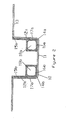
La figure 2 représente une coupe en section transversale d'un article selon un
deuxième mode de réalisation. L'article comprend un élément rigide 10 en forme de U,
avec une base 11, et deux parois opposées 12a; 12b formant les deux branches du U.
Les extrémités du U présentent des méplats 13. La base et les parois forment des
angles 14a; 14b. L'article comprend deux parties en matière thermoplastique 15a; 15b
positionnées chacune, au moins en partie dans les angles 14a; 14b. Chacune des
deux parties en matière thermoplastique prend appui sur la base 16a; 16b et sur la
paroi relative à l'angle dans lequel elle est positionnée 17a; 17b. Chacune des parties
positionnées dans les angle présente une portion tubulaire avec un creux 18a; 18b.
Les moyens de solidarisation entre l'élément rigide et la partie en matière
thermoplastique ne sont pas représentés sur cette figure.Figure 2 shows a cross-section of an article according to a
second embodiment. The article comprises a
La figure 3 représente une vue partielle en trois dimensions d'un article selon un
troisième mode de réalisation de l'invention. Le profile d l'article selon ce mode de
réalisation est voisin de celui représenté en figure 2. L'article comporte en plus des
nervures de renfort 20 entre les deux parties en matière thermoplastique positionnées
dans les angles. L'élément rigide et les parties en matière thermoplastique sont
solidarisés par débordement (21) de matière thermoplastique à travers un orifice percé
dans l'élément rigide.FIG. 3 represents a partial three-dimensional view of an article according to a
third embodiment of the invention. The profile of the article according to this mode of
realization is close to that shown in Figure 2. The article also includes
reinforcing
Claims (20)
- Article comprising a part consisting of a rigid element (1) of elongate shape, at least one part of which has a cross section which has a profile defining a concave space, and comprising at least one part made of thermoplastic material (2) associated with the rigid element and positioned in the concave space of the rigid element, characterized in that the part made of thermoplastic material is in contact on at least two lines which are continuous in the longitudinal direction, and in that the part made of thermoplastic material has a cross section comprising at least one hollow (4).
- Article according to Claim 1, characterized in that the part made of thermoplastic material (2) positioned in the concave space of the rigid element (1) has a profile which is the conjugate of the concave space.
- Article according to Claim 2, characterized in that the cross section of the rigid element (1) is closed.
- Article according to Claim 1, characterized in that the profile of the rigid element (10) is defined by at least one base (11) and two opposed walls (12a, 12b) defining two corners (14a, 14b) with the base and in that it comprises at least two parts made of thermoplastic material (15a, 15b) with hollow cross sections (18a, 18b) positioned in each corner, each of these parts resting along at least one portion of the base (16a, 16b) and at least one portion of the wall (17a, 17b) relative to the corner in which it is positioned.
- Article according to Claim 3, characterized in that the profile of the rigid element (10) is in the shape of a U or an I.
- Article according to one of Claims 4 or 5, characterized in that it comprises reinforcing ribs (20) made of thermoplastic material resting at least partly on the parts made of thermoplastic materials positioned in the corners defined by the walls and the base.
- Article according to one of the preceding claims, characterized in that it corresponds to the assembly of a rigid element (1) and of at least one moulded element made of thermoplastic material (2).
- Article according to Claim 7, characterized in that this assembly corresponds to insetting, welding, bonding, riveting or clipping.
- Article according to one of Claims 1 to 6, characterized in that the part made of thermoplastic material (2) is moulded inside the concave space.
- Article according to Claim 9, characterized in that the part made of thermoplastic material (2) and the rigid element (1) are secured by the protrusion of thermoplastic material through perforations made in the rigid element.
- Article according to one of Claims 9 to 10, characterized in that the part made of thermoplastic material (2) and the rigid element (1) are secured by complete or partial overmoulding of the rigid element.
- Article according to one of the preceding claims, characterized in that the rigid element (1) is a tubular or profiled metal component.
- Article according to one of the preceding claims, characterized in that the thermoplastic material is a polyamide.
- Article according to one of the preceding claims, characterized in that the part made of thermoplastic material (2) of hollow cross section comprises means for letting a fluid into and out of the interior of the hollow part.
- Use of an article according to one of Claims 1 to 14 in a fluid-transfer device.
- Use according to Claim 15, characterized in that the fluids are chosen from air, water, water containing glycol, fuels and oils.
- Use of an article according to one of Claims 1 to 14 for producing motor vehicle front face components.
- Use of an article according to one of Claims 1 to 14 in a heat-exchange device.
- Method for fabricating an article comprising at least one rigid element (1) a cross section of which has at least one part defining a concave space and comprising at least one element made of a moulded thermoplastic material (2), this method comprising at least the following steps:a) arranging, in an injection mould of chosen shape, a preformed rigid element (1) one cross section of which has at least one part defining a concave space,b) injecting molten thermoplastic material into the mould,
this method being characterized in that it comprises the following step:c) injecting a fluid, preferably a gas, through a needle into the molten thermoplastic material present in the concave space of the rigid element (1). - Method for fabricating an article comprising at least one rigid element (1) a cross section of which has at least one part defining a concave space and comprising at least one element made of a moulded thermoplastic material (2), this method comprising at least the following steps:a) arranging, in an injection mould of chosen shape, a rigid element (1) that is to be preformed,b) preforming the rigid element by pressing or by hot forming in the mould, the preform having a cross section which has at least one part defining a concave space,c) injecting molten thermoplastic material into the mould,
this method being characterized in that it comprises the following step:d) injecting a fluid, preferably a gas, through a needle into the molten thermoplastic material present in the concave space of the rigid element (1).
Applications Claiming Priority (5)
| Application Number | Priority Date | Filing Date | Title |
|---|---|---|---|
| FR9903766A FR2791297B1 (en) | 1999-03-23 | 1999-03-23 | MANUFACTURED ARTICLE BASED ON A THERMOPLASTIC MATERIAL COMPRISING A RIGID ELEMENT |
| FR9903766 | 1999-03-23 | ||
| FR9916711 | 1999-12-30 | ||
| FR9916711A FR2803241B3 (en) | 1999-12-30 | 1999-12-30 | MIXED ARTICLES COMPRISING A RIGID PART AND A PART BASED ON A THERMOPLASTIC MATERIAL |
| PCT/FR2000/000703 WO2000056517A1 (en) | 1999-03-23 | 2000-03-21 | Mixed articles comprising a rigid part and a part based on a thermoplastic material |
Publications (2)
| Publication Number | Publication Date |
|---|---|
| EP1163094A1 EP1163094A1 (en) | 2001-12-19 |
| EP1163094B1 true EP1163094B1 (en) | 2004-02-11 |
Family
ID=26234886
Family Applications (1)
| Application Number | Title | Priority Date | Filing Date |
|---|---|---|---|
| EP00911016A Expired - Lifetime EP1163094B1 (en) | 1999-03-23 | 2000-03-21 | Mixed articles comprising a rigid part and a part based on a thermoplastic material, and manufacturing method |
Country Status (7)
| Country | Link |
|---|---|
| US (1) | US6858276B1 (en) |
| EP (1) | EP1163094B1 (en) |
| JP (1) | JP3837025B2 (en) |
| AT (1) | ATE259287T1 (en) |
| AU (1) | AU3302100A (en) |
| DE (1) | DE60008220T2 (en) |
| WO (1) | WO2000056517A1 (en) |
Families Citing this family (27)
| Publication number | Priority date | Publication date | Assignee | Title |
|---|---|---|---|---|
| DE10003575A1 (en) * | 2000-01-27 | 2001-08-02 | Behr Gmbh & Co | Component for a motor vehicle |
| US6908132B2 (en) | 2001-02-28 | 2005-06-21 | E. I. Du Pont De Nemours And Company | Integral structures of metal and plastic |
| EP1415897B1 (en) * | 2002-11-01 | 2006-12-13 | Calsonic Kansei Corporation | Cross member and manufacturing method thereof |
| US6834913B2 (en) | 2002-11-13 | 2004-12-28 | Visteon Global Technologies, Inc. | Structural composite air handling duct |
| US6688680B1 (en) | 2002-12-17 | 2004-02-10 | Bayer Polymers Llc | Molded cross vehicle beam |
| EP1600272A1 (en) * | 2003-02-12 | 2005-11-30 | Sintex Beteiligungs, GmbH. | Method for the production of a structural part comprising a rigid material and a plastic material, and structural composite part thus obtained |
| DE20310656U1 (en) * | 2003-07-11 | 2003-09-11 | Hella Behr Fahrzeugsysteme | Hybrid component for motor vehicles |
| FR2864816B1 (en) † | 2004-01-02 | 2006-04-14 | Plastic Omnium Cie | METHOD FOR MANUFACTURING A BODY COMPONENT OF A MOTOR VEHICLE, BODY PIECE |
| US7721496B2 (en) * | 2004-08-02 | 2010-05-25 | Tac Technologies, Llc | Composite decking material and methods associated with the same |
| US8003202B2 (en) * | 2006-06-16 | 2011-08-23 | E.I. Du Pont De Nemours And Company | Semiaromatic polyamide composite article and processes for its preparation |
| DE102006061522A1 (en) * | 2006-12-20 | 2008-06-26 | Faurecia Innenraum Systeme Gmbh | Method for producing a carrier having a hollow profile and carrier with a hollow profile |
| DE102007060394A1 (en) * | 2007-12-14 | 2009-06-18 | Robert Bosch Gmbh | Multi-component injection-molded part with cohesive seal |
| FR2924973B1 (en) * | 2007-12-18 | 2011-06-24 | Trelleborg Reims | METHOD FOR MANUFACTURING PEDALS AND HYBRID LEVERS AND ITS APPLICATION TO AUTOMOTIVE BRAKE PEDALS |
| DE102008010834A1 (en) * | 2008-02-23 | 2009-08-27 | Daimler Ag | Frame component and a method for its production |
| DE102008017377A1 (en) * | 2008-04-05 | 2009-10-08 | Röchling Technische Teile KG | Lightweight component and method for producing this |
| FR2931785B1 (en) * | 2008-06-03 | 2010-12-31 | Peugeot Citroen Automobiles Sa | VEHICLE COVER, DEVICE AND METHOD FOR MANUFACTURING SUCH HOOD |
| FR2942649A3 (en) * | 2009-03-02 | 2010-09-03 | Renault Sas | Hollow body i.e. cooling water circulation pipe, manufacturing method for heat engine of motor vehicle, involves ejecting rigid profile outside mold by forming single piece i.e. pipe, with over molded hollow volume |
| GB2503494A (en) * | 2012-06-29 | 2014-01-01 | Bae Systems Plc | Heat exchanger comprising a fibre reinforced polymer composite |
| JP6109271B2 (en) * | 2015-02-06 | 2017-04-05 | 株式会社神戸製鋼所 | Junction structure and manufacturing method of junction structure |
| DE102015204494A1 (en) * | 2015-03-12 | 2016-09-15 | Hyundai Motor Company | Hybrid side skirts for a motor vehicle and manufacturing method thereof |
| FR3037558B1 (en) * | 2015-06-19 | 2017-05-26 | Airbus Operations Sas | METHOD FOR MANUFACTURING AN OVERMOLDING FUSELAGE PANEL AND FUSELAGE PANEL THUS OBTAINED |
| KR101923894B1 (en) * | 2016-09-27 | 2018-11-29 | 현대자동차주식회사 | seat back frame with hollow structure and method for manufacturing the same |
| CN113924208A (en) * | 2019-10-04 | 2022-01-11 | 日本制铁株式会社 | Metal-fiber-reinforced resin material composite, method for producing same, metal-fiber-reinforced resin composite unit, and automobile part |
| BE1027720B1 (en) * | 2019-10-30 | 2021-05-31 | Del Ponti Bv | Holder with carrier for fence |
| FR3103968A1 (en) * | 2019-11-28 | 2021-06-04 | Valeo Systemes Thermiques | Compartment for equipment liable to give off heat |
| FR3106700B1 (en) * | 2020-01-27 | 2022-06-17 | Valeo Systemes Thermiques | Compartment for equipment likely to generate heat |
| DE102022210374A1 (en) * | 2022-09-30 | 2024-04-04 | Volkswagen Aktiengesellschaft | Plastic hollow longitudinal beam and method for producing such a plastic hollow longitudinal beam |
Family Cites Families (14)
| Publication number | Priority date | Publication date | Assignee | Title |
|---|---|---|---|---|
| US3242239A (en) | 1961-08-16 | 1966-03-22 | Freeman Chemical Corp | Filling structural cavities |
| FR2191577A5 (en) | 1972-07-05 | 1974-02-01 | Gregoire Et L B Rilleau | Reinforcement of hollow thin wall profiles - by continuous introduction of a rigid foam filling |
| DE2716676A1 (en) | 1977-04-15 | 1978-10-19 | Herbert Heinemann | Tongued edged sheet metal cladding panel - has front embossed structured patterns and rear hollow foamed insulating plastics filling |
| HU195460B (en) | 1983-09-26 | 1988-05-30 | Muanyagipari Kutato Intezet | Process for producing steel structures reinforced with polymer concrete |
| US5049349A (en) * | 1985-12-13 | 1991-09-17 | The Procter & Gamble Company | Method for making a blown bag-in-box composite container |
| DE3742457A1 (en) | 1987-12-15 | 1989-06-29 | Dynamit Nobel Ag | MANUFACTURING PROCESS FOR PLASTIC MOLDED PARTS WITH DECORATIVE-STAMPED SURFACE COATING |
| FR2624425B1 (en) * | 1987-12-15 | 1990-05-25 | Plastic Omnium Cie | PROCESS FOR OVERMOLDING NON-RIGID SHEETS BY INJECTION OF THERMOPLASTIC MATERIALS TO MAKE COMPOSITE PARTS |
| JP2537668B2 (en) | 1988-09-19 | 1996-09-25 | 豊田合成株式会社 | Method for manufacturing resin molded products |
| DE3839855A1 (en) * | 1988-11-25 | 1990-05-31 | Bayer Ag | LIGHTWEIGHT COMPONENT |
| US5190803A (en) * | 1988-11-25 | 1993-03-02 | Bayer Aktiengesellschaft | Structural shell with reinforcing ribs connected via perforations |
| JP2780117B2 (en) | 1989-09-01 | 1998-07-30 | 三井化学株式会社 | Manufacturing method of hollow molded body |
| US5456957A (en) * | 1992-03-06 | 1995-10-10 | The Standard Products Company | Body side molding and method |
| JP3574174B2 (en) | 1994-05-02 | 2004-10-06 | 旭化成ケミカルズ株式会社 | Molding method of multilayer molded body |
| US5599599A (en) * | 1995-07-06 | 1997-02-04 | University Of Central Florida | Fiber reinforced plastic ("FRP")-concrete composite structural members |
-
2000
- 2000-03-21 DE DE60008220T patent/DE60008220T2/en not_active Expired - Lifetime
- 2000-03-21 EP EP00911016A patent/EP1163094B1/en not_active Expired - Lifetime
- 2000-03-21 AT AT00911016T patent/ATE259287T1/en not_active IP Right Cessation
- 2000-03-21 AU AU33021/00A patent/AU3302100A/en not_active Abandoned
- 2000-03-21 US US09/937,381 patent/US6858276B1/en not_active Expired - Fee Related
- 2000-03-21 WO PCT/FR2000/000703 patent/WO2000056517A1/en active IP Right Grant
- 2000-03-21 JP JP2000606401A patent/JP3837025B2/en not_active Expired - Fee Related
Also Published As
| Publication number | Publication date |
|---|---|
| WO2000056517A1 (en) | 2000-09-28 |
| JP2002539969A (en) | 2002-11-26 |
| DE60008220D1 (en) | 2004-03-18 |
| ATE259287T1 (en) | 2004-02-15 |
| JP3837025B2 (en) | 2006-10-25 |
| EP1163094A1 (en) | 2001-12-19 |
| US6858276B1 (en) | 2005-02-22 |
| DE60008220T2 (en) | 2004-07-08 |
| AU3302100A (en) | 2000-10-09 |
Similar Documents
| Publication | Publication Date | Title |
|---|---|---|
| EP1163094B1 (en) | Mixed articles comprising a rigid part and a part based on a thermoplastic material, and manufacturing method | |
| EP1464848B1 (en) | Tubular assembly having an internal plug | |
| CN201687812U (en) | Reinforced thermoplastic structure connecting assembly used for vehicles | |
| FR3066466B1 (en) | STORAGE BIN FOR ASSEMBLY ON A BODY STRUCTURE OF A MOTOR VEHICLE. | |
| WO2010049632A1 (en) | Lining for a vehicle bonnet | |
| FR2803241A1 (en) | Article for use in buildings, furniture, vehicles, consumer goods, etc has elongate rigid element whose profile has concave part in line contact with thermoplastic element(s) | |
| WO2006061490A1 (en) | Motor vehicle front surface support comprising an integrated cavity | |
| FR2791297A1 (en) | Article for use in buildings, furniture, vehicles, consumer goods, etc has elongate rigid element whose profile has concave part in line contact with thermoplastic element(s) | |
| FR2898566A1 (en) | Bumper beam for motor vehicle, has external beam defining cavity at bottom of beam and open in direction of interior of vehicle, and internal beam received in cavity and supported against bottom of external beam | |
| FR3041303A1 (en) | STRUCTURAL AND / OR ENERGY ABSORPTION ELEMENT FOR A MOTOR VEHICLE AND METHOD FOR MANUFACTURING THE SAME | |
| WO2007110321A1 (en) | Motor vehicle front face of the metal/plastic composite type | |
| FR2793438A1 (en) | Article for vehicles, buildings, and furniture, has rigid element part with concave cross section and thermoplastic foam reinforcement lies at least partly in concave space | |
| EP1997689A1 (en) | Bumper beam for a vehicle comprising outer and inner beams | |
| EP2237942B1 (en) | Method for making a cellular structure | |
| EP1632424B1 (en) | Injection moulding method for a hybrid part with a metallic insert | |
| EP1166995A1 (en) | Process for producing a hollow panel which are lined on both sides and the produced panel | |
| FR3031951A1 (en) | METHOD FOR THE MANUFACTURING OF A BODY OF A MOTOR VEHICLE IN MIXED CONSTRUCTION | |
| ITTO20000854A1 (en) | PLASTIC TANK FOR THE FUEL OF A VEHICLE. | |
| EP0635349A1 (en) | Method for the manufacture of spoilers for cars | |
| FR2745077A1 (en) | PLASTIC COLLECTOR BOX FOR HEAT EXCHANGER | |
| FR2879552A1 (en) | Motor vehicle body component comprises windscreen pillar made from two joined half shells with supports for windscreen and/or side window | |
| FR3041313A1 (en) | BAY END FOR MOTOR VEHICLE | |
| FR2903442A1 (en) | Modular top-of-the-range swimming pool constructing device, has panels molded in polynorbomene resin, and sealing unit sealing between panels and bottom element, where fixation modes i.e. insert, fasten panels together in adjacent manner | |
| FR2469268A1 (en) | Plastics component esp. handles or fittings integrally formed - onto porous article by direct moulding in thermoplastic state | |
| EP4119322A1 (en) | Method for moulding a part for a motor vehicle comprising a metal insert |
Legal Events
| Date | Code | Title | Description |
|---|---|---|---|
| PUAI | Public reference made under article 153(3) epc to a published international application that has entered the european phase |
Free format text: ORIGINAL CODE: 0009012 |
|
| 17P | Request for examination filed |
Effective date: 20011015 |
|
| AK | Designated contracting states |
Kind code of ref document: A1 Designated state(s): AT BE CH CY DE DK ES FI FR GB GR IE IT LI LU MC NL PT SE |
|
| 17Q | First examination report despatched |
Effective date: 20020410 |
|
| GRAP | Despatch of communication of intention to grant a patent |
Free format text: ORIGINAL CODE: EPIDOSNIGR1 |
|
| RTI1 | Title (correction) |
Free format text: MIXED ARTICLES COMPRISING A RIGID PART AND A PART BASED ON A THERMOPLASTIC MATERIAL, AND MANUFACTURING METHOD |
|
| GRAS | Grant fee paid |
Free format text: ORIGINAL CODE: EPIDOSNIGR3 |
|
| GRAA | (expected) grant |
Free format text: ORIGINAL CODE: 0009210 |
|
| AK | Designated contracting states |
Kind code of ref document: B1 Designated state(s): AT BE CH CY DE DK ES FI FR GB GR IE IT LI LU MC NL PT SE |
|
| PG25 | Lapsed in a contracting state [announced via postgrant information from national office to epo] |
Ref country code: IT Free format text: LAPSE BECAUSE OF FAILURE TO SUBMIT A TRANSLATION OF THE DESCRIPTION OR TO PAY THE FEE WITHIN THE PRESCRIBED TIME-LIMIT;WARNING: LAPSES OF ITALIAN PATENTS WITH EFFECTIVE DATE BEFORE 2007 MAY HAVE OCCURRED AT ANY TIME BEFORE 2007. THE CORRECT EFFECTIVE DATE MAY BE DIFFERENT FROM THE ONE RECORDED. Effective date: 20040211 Ref country code: GB Free format text: LAPSE BECAUSE OF FAILURE TO SUBMIT A TRANSLATION OF THE DESCRIPTION OR TO PAY THE FEE WITHIN THE PRESCRIBED TIME-LIMIT Effective date: 20040211 Ref country code: ES Free format text: LAPSE BECAUSE OF FAILURE TO SUBMIT A TRANSLATION OF THE DESCRIPTION OR TO PAY THE FEE WITHIN THE PRESCRIBED TIME-LIMIT Effective date: 20040211 Ref country code: NL Free format text: LAPSE BECAUSE OF FAILURE TO SUBMIT A TRANSLATION OF THE DESCRIPTION OR TO PAY THE FEE WITHIN THE PRESCRIBED TIME-LIMIT Effective date: 20040211 Ref country code: IE Free format text: LAPSE BECAUSE OF FAILURE TO SUBMIT A TRANSLATION OF THE DESCRIPTION OR TO PAY THE FEE WITHIN THE PRESCRIBED TIME-LIMIT Effective date: 20040211 Ref country code: CY Free format text: LAPSE BECAUSE OF FAILURE TO SUBMIT A TRANSLATION OF THE DESCRIPTION OR TO PAY THE FEE WITHIN THE PRESCRIBED TIME-LIMIT Effective date: 20040211 Ref country code: FI Free format text: LAPSE BECAUSE OF FAILURE TO SUBMIT A TRANSLATION OF THE DESCRIPTION OR TO PAY THE FEE WITHIN THE PRESCRIBED TIME-LIMIT Effective date: 20040211 Ref country code: AT Free format text: LAPSE BECAUSE OF FAILURE TO SUBMIT A TRANSLATION OF THE DESCRIPTION OR TO PAY THE FEE WITHIN THE PRESCRIBED TIME-LIMIT Effective date: 20040211 |
|
| REG | Reference to a national code |
Ref country code: GB Ref legal event code: FG4D Free format text: NOT ENGLISH |
|
| REG | Reference to a national code |
Ref country code: CH Ref legal event code: EP |
|
| REG | Reference to a national code |
Ref country code: IE Ref legal event code: FG4D Free format text: FRENCH |
|
| REF | Corresponds to: |
Ref document number: 60008220 Country of ref document: DE Date of ref document: 20040318 Kind code of ref document: P |
|
| PG25 | Lapsed in a contracting state [announced via postgrant information from national office to epo] |
Ref country code: LU Free format text: LAPSE BECAUSE OF NON-PAYMENT OF DUE FEES Effective date: 20040321 |
|
| PG25 | Lapsed in a contracting state [announced via postgrant information from national office to epo] |
Ref country code: BE Free format text: LAPSE BECAUSE OF NON-PAYMENT OF DUE FEES Effective date: 20040331 Ref country code: CH Free format text: LAPSE BECAUSE OF NON-PAYMENT OF DUE FEES Effective date: 20040331 Ref country code: LI Free format text: LAPSE BECAUSE OF NON-PAYMENT OF DUE FEES Effective date: 20040331 Ref country code: MC Free format text: LAPSE BECAUSE OF NON-PAYMENT OF DUE FEES Effective date: 20040331 |
|
| PG25 | Lapsed in a contracting state [announced via postgrant information from national office to epo] |
Ref country code: GR Free format text: LAPSE BECAUSE OF FAILURE TO SUBMIT A TRANSLATION OF THE DESCRIPTION OR TO PAY THE FEE WITHIN THE PRESCRIBED TIME-LIMIT Effective date: 20040511 Ref country code: SE Free format text: LAPSE BECAUSE OF FAILURE TO SUBMIT A TRANSLATION OF THE DESCRIPTION OR TO PAY THE FEE WITHIN THE PRESCRIBED TIME-LIMIT Effective date: 20040511 Ref country code: DK Free format text: LAPSE BECAUSE OF FAILURE TO SUBMIT A TRANSLATION OF THE DESCRIPTION OR TO PAY THE FEE WITHIN THE PRESCRIBED TIME-LIMIT Effective date: 20040511 |
|
| NLV1 | Nl: lapsed or annulled due to failure to fulfill the requirements of art. 29p and 29m of the patents act | ||
| GBV | Gb: ep patent (uk) treated as always having been void in accordance with gb section 77(7)/1977 [no translation filed] |
Effective date: 20040211 |
|
| REG | Reference to a national code |
Ref country code: IE Ref legal event code: FD4D |
|
| BERE | Be: lapsed |
Owner name: RHODIA ENGINEERING PLASTICS SA Effective date: 20040331 |
|
| REG | Reference to a national code |
Ref country code: CH Ref legal event code: PL |
|
| PLBE | No opposition filed within time limit |
Free format text: ORIGINAL CODE: 0009261 |
|
| STAA | Information on the status of an ep patent application or granted ep patent |
Free format text: STATUS: NO OPPOSITION FILED WITHIN TIME LIMIT |
|
| 26N | No opposition filed |
Effective date: 20041112 |
|
| PG25 | Lapsed in a contracting state [announced via postgrant information from national office to epo] |
Ref country code: PT Free format text: LAPSE BECAUSE OF NON-PAYMENT OF DUE FEES Effective date: 20040711 |
|
| PGFP | Annual fee paid to national office [announced via postgrant information from national office to epo] |
Ref country code: FR Payment date: 20140311 Year of fee payment: 15 |
|
| PGFP | Annual fee paid to national office [announced via postgrant information from national office to epo] |
Ref country code: DE Payment date: 20140417 Year of fee payment: 15 |
|
| REG | Reference to a national code |
Ref country code: DE Ref legal event code: R119 Ref document number: 60008220 Country of ref document: DE |
|
| REG | Reference to a national code |
Ref country code: FR Ref legal event code: ST Effective date: 20151130 |
|
| PG25 | Lapsed in a contracting state [announced via postgrant information from national office to epo] |
Ref country code: DE Free format text: LAPSE BECAUSE OF NON-PAYMENT OF DUE FEES Effective date: 20151001 |
|
| PG25 | Lapsed in a contracting state [announced via postgrant information from national office to epo] |
Ref country code: FR Free format text: LAPSE BECAUSE OF NON-PAYMENT OF DUE FEES Effective date: 20150331 |