EP1163076B1 - Schneidplatte und kugelkopffräswerkzeug - Google Patents
Schneidplatte und kugelkopffräswerkzeug Download PDFInfo
- Publication number
- EP1163076B1 EP1163076B1 EP00912391A EP00912391A EP1163076B1 EP 1163076 B1 EP1163076 B1 EP 1163076B1 EP 00912391 A EP00912391 A EP 00912391A EP 00912391 A EP00912391 A EP 00912391A EP 1163076 B1 EP1163076 B1 EP 1163076B1
- Authority
- EP
- European Patent Office
- Prior art keywords
- cutting
- angle
- cutting insert
- bevel
- clearance
- Prior art date
- Legal status (The legal status is an assumption and is not a legal conclusion. Google has not performed a legal analysis and makes no representation as to the accuracy of the status listed.)
- Expired - Lifetime
Links
Images


Classifications
-
- B—PERFORMING OPERATIONS; TRANSPORTING
- B23—MACHINE TOOLS; METAL-WORKING NOT OTHERWISE PROVIDED FOR
- B23C—MILLING
- B23C5/00—Milling-cutters
- B23C5/02—Milling-cutters characterised by the shape of the cutter
- B23C5/10—Shank-type cutters, i.e. with an integral shaft
- B23C5/1009—Ball nose end mills
- B23C5/1027—Ball nose end mills with one or more removable cutting inserts
- B23C5/1036—Ball nose end mills with one or more removable cutting inserts having a single cutting insert, the cutting edges of which subtend 180 degrees
Definitions
- the invention relates to a cutting insert for a ball end mill (Finger milling tool), especially for form milling, with two opposing flat contact surfaces, two inclined at a positive clearance angle and each arcuate extending over an angle of at least 90 ° Open spaces, two rotationally symmetrically arranged part-circular, essentially diametrically opposite cutting edges and a hole for receiving a clamping screw.
- a ball end mill Finger milling tool
- the invention further relates to a ball end mill with a Tool holder that has a recess for receiving a cutting insert of the aforementioned type, with a clamping screw is fixed.
- molds In the production of hollow molds, some of which have complex geometries, efficient cutting tools are required which, above all, allow the necessary machining work to be carried out in a short time with high accuracy.
- Molds especially as forging dies, consist of a hard material that can only be manufactured with a corresponding geometrically precise tool to avoid manual reworking.
- the multi-dimensionally movable end mill used for this purpose must be suitable for cutting both in the axial (feed) direction and perpendicular to it. Because of the required manufacturing accuracy, this presupposes part-circular cutting edges whose deviation from the circular shape should be as small as possible. The tool cutting edges are subjected to considerable loads during so-called high-speed milling.
- the cutting edge of the tool used should be as tough as possible in order to be able to withstand the pressure generated during machining in the center.
- a cutting insert of the type mentioned is from the EP 0 008 972 known.
- a milling tool with a tool holder that fits in one shaped recess an exchangeable cutting insert records is also described in DE 30 30 442 A1.
- the tool holder to provide a clamping member that the Then insert the insert on the contact surface only after they had previously been pressed against a counter bearing under prestress is.
- the receiving shaft has one through it at the front end transverse groove on, one groove wall a contact surface forms and in which the insert used precisely is insertable.
- the counter bearing is formed by the groove base.
- In the other groove wall there is one for tapping aligned screw hole, which for recessed arrangement a head of a fastening screw is countersunk.
- the Counter bearing of the tool holder should be in the direction of the longitudinal axis have adjustable support member of the receiving shaft, in a corresponding recess on the circumference of the Insert engages positively.
- the insert itself has two cutting edges that run to the longitudinal axis of the milling tool seen are assigned to each other symmetrically. To form a Clearance angle should grind the two cutting edges on the plate circumference his.
- WO 94/23873 describes one for a ball end milling cutter certain insert suggested at least two symmetrically arranged, as a carrier for cutting edges Inserts serving cutting layers are provided on top of each other opposite contact surfaces forming sides of the Insert base body are arranged. These bets can e.g. as well as the cutting insert base made of hard metal consist of or of another material, e.g. a polycrystalline Layer of diamond, a cubic boron nitride or other substances that may still contain wear-reducing substances, in particular alumina partially or completely coated are.
- the circular segment-shaped inserts are on the insert body e.g. fixed by soldering.
- the insert body has a cross-section extending over 180 ° circular or approximately circular contour on, on the symmetrically converging edges and finally a connect this connecting base edge, creating a prismatic Contact surface is formed, which is positive in the tensioned state on a correspondingly trained prismatic Contact surface of the tool holder cutting insert seat is in contact.
- a clamping screw is used as clamping device, which is a Passes through the hole of the cutting insert.
- a cutting insert is described in DE 197 21 283 A1 described type, its essentially diametrical opposing cutting edges along with those on it following chip faces can take the following positions:
- one of the rake faces runs axially while the other is located slightly in the middle.
- Both rake faces can be arranged axially, whereby if necessary, the front end of one rake face with a bevel is equipped, the end of which lies in the middle, whereby a higher robustness of the cutting insert can be achieved should.
- both rake faces can be arranged in the middle be, being between their two ends in the neighborhood the axis two small bevels can be provided that lead to certain intolerances, which in rough machining (Roughing) are tolerable.
- the bevels can also run at the end of a radius that is transmitted.
- the chamfer is preferably in relation to the flat contact surfaces arranged negatively inclined, especially under one Angle between 8 ° and 30 °, further preferably between 10 ° and 20 ° or between 13 ° and 15 °.
- the bevel angle is 30 ° to 60 °, preferably 45 °.
- the chamfer for axial center runs continuously (to 0 mm).
- the present invention includes all embodiments in which starting from about the center, i.e. the longitudinal axis of the milling cutter, the chamfer increases continuously up to its maximum width and then rejuvenates towards peripheral areas, the chamfer extending over an angular range of Cutting edge extends, preferably between 3 ° and 100 ° lies.
- bevels with a larger bevel angle between 30 ° and 60 ° bevel widths from 0.01 mm to 0.08 mm, preferably 0.02 mm to 0.05 mm.
- the chamfer extends over angular ranges the cutting edge from 3 ° to 8 °, 8 ° to 20 °, 20 ° to 45 ° or 45 ° to 100 °.
- the present invention comprises so-called finishing inserts, where the cutting edges are arranged in the middle are, the distance between the sub-levels of Cutting 0.015 mm to 0.5 mm, preferably 0.02 mm to 0.2 mm, is. In the transition area, i.e. from the periphery to the center the cutting edges rise each time.
- an embodiment can be used in so-called roughing operations can be selected in which the cutting edges of each the periphery towards the center fall into an area that is at least 0.4 mm, preferably at least 0.6 mm. Outside this central area, which is due to the sloping Cutting is then already stabilized, preferably over an angular range of the cutting edge ( ⁇ ) between 30 ° and 100 °, the mentioned bevel arranged.
- the cutting edge in the center area can be manufactured by realizing that the rake face on the opposite sides in the center each "an oblique Grind "receives, which is in the form of a point is.
- the bevel is ground in the peripheral area, i.e.
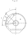
- the starting angle ⁇ which defines the position of the chamfered cutting area either from the boundary between the center and peripheral cutting edge (see FIG. 9) or is in the range from 5 ° to 60 °, preferably 12 ° to 35 °, cf. Fig. 13.
- ⁇ which defines the position of the chamfered cutting area either from the boundary between the center and peripheral cutting edge (see FIG. 9) or is in the range from 5 ° to 60 °, preferably 12 ° to 35 °, cf. Fig. 13.
- the kink between the center and Peripheral cutting edge defused Stand by this configuration the cutting edges, the peripheral lying Cutting edges are in parallel planes to each other. This results in greater stability and break resistance along the entire cutting edge since the resulting one Cutting force is approximately directed into the contact surface. This has an effect in rough operating conditions and in short chipping Tools, with 3-axis milling with the Milling cutters and 5-axis milling.
- the cutting insert in the rear has concentricity Area prismatic contact surfaces, which are always reproducible exact positioning of the cutting insert in the tool holder guarantee.
- the free areas of the cutting insert are at a clearance angle inclined between 0 ° and 30 °, preferably 10 ° and 20 ° lies.
- the free surface is convex or angled is, preferably to the respective cutting edge
- Adjacent free area with a clearance angle between 0 ° and 15 ° is inclined, resulting in a correspondingly large wedge angle is created, and the open space adjacent to the contact surface is inclined at a larger clearance angle, which is preferably is between 7 ° and 35 °.
- the width of the to the Cutting edge adjacent free area is between 5% and 30%, preferably 7% and 15% of the distance between the flat contact surfaces (Height of the cutting insert).
- the open spaces, the cutting edge areas further out can also have a smaller clearance angle than inside (in Center).
- the present invention thus comprises on the one hand Cutting insert for a ball mill, in which the diametrical opposite cutting edges do not lie in one plane.
- the Circumferential cutting i.e. the more peripheral ones Cutting edge areas of each cutting edge lie in relation to one another parallel planes.
- the two cutting edges run in the center area or the central cutting edge areas in the direction of the axis of rotation of the tool towards each other.
- Opposing open spaces are preferably below the Circumferential cutting edge areas are conical or conical, while the free space below each other to the axis of rotation tapering center cutting areas compared to bulge conical open areas so that all cutting areas approximately lying on a common envelope, whereby optimal round cuts can be produced.
- the roughnesses R a and / or R z on the chamfer surface can be lower than on the rake surface and / or the free surface, preferably in a ratio of 30 to 80%. This results in less chipping, with the advantage of a reduced tendency to micro-crumbling of the cutting edge, a longer service life and a higher surface quality of the workpiece.
- Chamfers that extend from the center over an angular range the cutting edge of a maximum of 45 ° have the advantage that the stability and break resistance near the cutting center is increased by cutting speed 0 is. This is particularly important for 3-axis milling with a cutter angle of 0 °, for high-strength machining or hard steel and cast materials or with axially immersing ones ("drilling") feed movements of the milling cutter positive out.
- a further reduction of the radial forces is achieved in that the rake faces following the Cutting in the chamfered and / or non-chamfered cutting areas be formed with a chip mold trough.
- the rake angle the chip mold cavity ( ⁇ ) is between 5 ° and 30 °, preferably between 10 ° and 20 °.
- the chip mold recess can be ground or shaped directly, e.g. by pressing and sintering. Farther the chip mold trough runs through the angle ( ⁇ ) from 5 ° to 20 ° defined distance from the center.
- All cutting inserts described can be made of coated Tungsten carbide or a coated cermet, where the coating by means of a PVD or a CVD and / or a medium temperature CVD process has been applied.
- the cutting plates can be made in particular with a layer a cubic boron nitride or a polycrystalline diamond be covered. This advantageously results in a broader application of highly wear-resistant coated cutting materials in connection with the chamfered cutting edge, with which a higher process reliability and longer downtimes are possible, because chamfered cutting of coated inserts inevitable loss of toughness of the substrate material and counteract the risk of cutting edges breaking.
- the cutting insert can of course be made of highly wear-resistant Tungsten carbide, a cermet, an oxide ceramic or a mixed ceramic, from the ceramics mentioned with or exist without coating. Possibly. can use these cutting inserts also from a nitride ceramic or a coated nitride ceramic exist, where appropriate also embodiments as in the WO 94/23873 are basically described, can be implemented, however with the proviso of a chamfer according to the invention.
- the present invention also relates to a ball end mill with a tool holder that has a recess for receiving the has cutting insert described above, with a Clamping screw is fixed.
- the plate seat of the tool holder has corresponding contact surfaces with the prismatic Contact surfaces of the cutting insert in the rear area form a form-fitting system in the tensioned state.
- the cutting inserts shown in the figures are in essentially plate-shaped and have two contact surfaces 20, 21 and a middle mounting hole 22 for Inclusion of a clamping screw.
- a longitudinal axis 23 which is also the axis of rotation of the copy router with the is clamped cutting insert, cutting edges 24 and 25 arranged, each over an angular range of approx. 100 °, measured from the longitudinal axis 23, extend.
- the Cutting edges are formed by free areas 26, 27 on the one hand and Rake face sections ⁇ 28, 29 formed on the other hand.
- Each Starting from the rake face plane 28, 29, one extends in the present case angled flank 30, which is a connecting surface forms to the upper or lower contact surface.
- the cutting insert is prismatic in the rear area arranged contact surfaces 31 and 32 in a positive Investment in correspondingly designed investment areas of the Fit the insert seat of a tool holder in the clamped state. In the area surrounding the center (see FIG. 5) the Rising edge in a throat 34, which - depending on bottom or over-center cutting arrangement - by concluding Grinding is manufactured.
- the subject of the present invention is a bevel, which as chamfer 35 only over an angle ⁇ of approximately 20 ° (see FIG. 3) or ⁇ (approx. 45 °, see Fig. 4) or over the entire cutting edge (see Fig. 2), i.e. extends over approx. 100 °.
- the the Cutting edge stabilizing chamfer tapers on both of them Ends, i.e. in particular towards the center 36, to a width of 0 and has (see Fig. 7) a maximum width a, which in Range is from 0.08 mm to 0.15 mm.
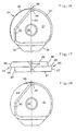
- FIG. 16 show an embodiment in which instead 1-3, an exposure 40 is provided is.
- This exposure 40 favors unimpeded chip flow in the center area.
- the ends Exposure 40 by a dimension b, which is about 0.1 mm, before Center that is stabilized accordingly.
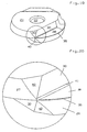
- 19 and 20 illustrate an embodiment in which the chamfer 35 ends where the Rake face 28, or 29 adjacent to a fillet 41, the Represents transition to edge 30.
- FIG. 1 to 8 and 14 to 20 illustrated embodiments are the cutting 24, 25 arranged slightly in the middle in the chamfered areas and rise as shown in FIG. 6 each from the periphery to the center 36.
- the Cutting inserts according to Fig. 1 to 7 and 14 to 20 are for Finishing operations used.
- the clearance angle at which the free areas 26, 27 are arranged is at least 2 °.
- Fig. 8 can also be angled, being adjacent in the cutting edge Area 261, 271 a short open space section one has a slight inclination of 2 ° to a maximum of 13 °, while the adjoining open space section 262, 272 a larger one Has clearance angle of 14 ° to 30 °.
- the height of the along the Cutting edge of equally wide open-space sections 261, 271 is a maximum of one third of the total height of the open space 26, 27 or the measure resulting from the individual heights of the open spaces 261 and 262 or 271 and 272 results.
- Fig. 13 shows an embodiment in which the Area of the chamfered cutting edge 24 at an angle ⁇ of 40 ° to 60 ° begins. This design enables targeted cutting edge stabilization in the cutting areas where the maximum effective voltage thicknesses and local loads occur.
- the distance c (see Fig. 12) is preferably 0.05 to 0.25 mm wide selected.
- Those shown in Figs. 9 to 13 Inserts are primarily suitable for roughing. in the with the exception of those that are only arranged peripherally here The same design features can be selected that also apply to FIG. 1 to 8 have already been described.
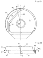
- the cutting insert shown in Figs. 21 and 22 has additionally a chip mold recess 42, which is located on the chamfer 35 the rake face 28 connects.
- This chip mold trough 42 ends Center 36 at a distance defined by the angle ⁇ , which is between 3 ° and 35 °.
- the chip mold has one Rake angle ⁇ between 5 ° and 30 °.
- the particular advantage of the present invention is that that a cutting edge stable, tough cutting insert in particular has been created for copy milling, the optimal concentricity has.
Landscapes
- Engineering & Computer Science (AREA)
- Mechanical Engineering (AREA)
- Milling Processes (AREA)
Description
- Fig. 1
- eine Draufsicht auf einen erfindungsgemäßen Schneideinsatz mit Blick auf die teilkreisförmigen Schneiden in Richtung der Werkzeugrotationsachse
- Fig. 2 bis 4
- jeweils Draufsichten auf Schneideinsätze in Richtung der Anlageflächen, wobei die Länge der Fase jeweils variiert,
- Fig. 5
- eine vergrößerte Teilansicht des Zentrumsbereiches eines Schneideinsatzes nach Fig. 3,
- Fig. 6
- eine Draufsicht auf das Zentrum eines Schneideinsatzes nach Fig. 17,
- Fig. 7
- eine Detailansicht der Schneidkante mit Fase,
- Fig. 8
- eine Draufsicht auf einen Schneideinsatz mit abgewinkelten Freiflächen,
- Fig. 9
- eine Draufsicht auf einen weiteren Schneideinsatz in Richtung der Auflagefläche,
- Fig. 10
- eine Draufsicht auf den Schneideinsatz nach Fig. 9 in Richtung der Schneidkante,
- Fig. 11
- eine Detailansicht der Spanfläche im Bereich der gefasten Schneidkante und
- Fig. 12
- eine Draufsicht auf das Zentrum des Schneideinsatzes nach Fig. 10.
- Fig. 13
- eine alternative Ausführungsform zu Fig. 9-12 hinsichtlich Startwinkel (η) und Winkelbereich (γ) in einer Draufsicht auf den Schneideinsatz in Richtung der Auflagefläche,
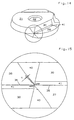
- Fig. 14
- in perspektivischer Ansicht eine alternative Ausführungsform eines Schneideinsatzes, mit einer untermittigen Anordnung der gefasten Schneidenbereiche, die sich bis in die Ausrundung zwischen Spanfläche und Spanformstufe erstrecken,
- Fig. 15
- eine detaillierte Draufsicht auf das Zentrum des Schneideinsatzes nach Fig. 14,
- Fig. 16, 18
- eine Draufsicht von alternativen Ausführungen zu Fig. 2
- Fig. 17
- eine Draufsicht auf das Zentrum für Schneideinsätze gemäß Fig. 16 oder 18,
- Fig. 19
- eine perspektivische Ansicht eines Schneideinsatzes nach Fig. 16,
- Fig. 20
- eine Detailansicht von Fig. 19,
- Fig. 21 und 22
- einen Schneideinsatz mit Spanformmulde.
Claims (10)
- Schneideinsatz für einen Kugelkopffräser, insbesondere zum Formenfräsen, mit zwei einander gegenüberliegenden Anlageflächen (20, 21), zwei unter einem Freiwinkel geneigten und sich jeweils über einen Winkel von mindestens 90° erstreckenden bogenförmigen Freiflächen (26, 27), zwei drehsymmetrisch angeordneten teilkreisförmigen und im wesentlichen diametral gegenüberliegenden Schneidkanten (24, 25) und einer Bohrung (22) zur Aufnahme einer Spannschraube, gekennzeichnet durch eine sich zumindest über einen Teilbereich der Schneidkante (24, 25) erstreckenden Fase (35), die gegenüber den Anlageflächen geneigt ist.
- Schneideinsatz nach Anspruch 1, dadurch gekennzeichnet, daß die Fase (35) in bezug auf die ebene Anlagefläche (20, 21) unter einem Winkel (δ) zwischen 8° und 30°, weiterhin vorzugsweise zwischen einem Winkel von 10° und 20°, oder unter einem Winkel zwischen 30° und 60°, vorzugsweise 45°, negativ geneigt ist.
- Schneideinsatz nach Anspruch 1 oder 2, dadurch gekennzeichnet, daß die unter einem Fasenwinkel < 30° angeordnete Fase (35) sich nur über einen Teilbereich der Schneide (24, 25) erstreckt und/oder an den Enden kontinuierlich zu 0 mm ausläuft und eine maximale Breite (a) von 0,05 mm bis 0,2 mm, vorzugsweise von 0,08 mm bis 0,15 mm, besitzt oder die unter einem Fasenwinkel zwischen 30° und 60° angeordnete Fase eine Breite zwischen 0,01 mm und 0,08 mm, vorzugsweise 0,02 mm bis 0,05 mm, aufweist, wobei die Fase (35) vorzugsweise zum axialen Zentrum (36) kontinuierlich auf 0 mm ausläuft.
- Schneideinsatz nach Anspruch 3, dadurch gekennzeichnet, daß die Fase (35) ausgehend von dem axialen Zentrum (36) sich kontinuierlich zu einer maximalen Breite (a) vergrößert und zu weiteren achsferneren Bereichen in ihrer Breite wieder zu 0 mm minimiert, wobei sich die Fase vorzugsweise über einen Winkelbereich (α) der Schneide von 3° bis 100° erstreckt, wobei sich die Fase, ausgehend vom Zentrum (36) alternativ entweder über einen Winkelbereich der Schneide von 3° bis 8°, über einen Winkelbereich der Schneide von 8° bis 20°, über einen Winkelbereich der Schneide von 20° bis 45° oder über einen Winkelbereich der Schneide von 45° bis 100° erstreckt.
- Schneideinsatz nach einem der Ansprüche 1 bis 4, dadurch gekennzeichnet, daß die Schneidkanten (24, 25) untermittig angeordnet sind und jeweils von der Peripherie zum Zentrum hin ansteigen und der Abstand der untermittigen Ebenen der Schneiden (24, 25) 0,015 mm bis 0,5 mm, vorzugsweise 0,02 mm bis 0,2 mm, beträgt.
- Schneideinsatz nach einem der Ansprüche 1 bis 4, dadurch gekennzeichnet, daß die Schneidkanten (24, 25) jeweils von der Peripherie zum Zentrum hin in einem Bereich (d) abfallen, der mindestens 0,4 mm, vorzugsweise mindestens 0,6 mm, beträgt, daß der Abstand der Schneidenebenen (e) um mindestens 0,3 mm, vorzugsweise nur mindestens 0,6 mm kleiner ist als die Gesamthöhe des Schneideinsatzes und daß außerhalb dieses Zentrumsbereiches eine Fase angeordnet ist, vorzugsweise über einen Winkelbereich (γ) der Schneide zwischen 30° und 100°, weiterhin vorzugsweise zwischen 45° und 100°.
- Schneideinsatz nach einem der Ansprüche 1 bis 6, gekennzeichnet durch prismatische Anlageflächen (31, 32) im hinteren Bereich und/oder dadurch, daß der Freiwinkel zwischen 2° und 30°, vorzugsweise 10° und 20°, liegt, wobei die Freifläche (261, 262; 271, 272) vorzugsweise konvex ausgebildet oder abgewinkelt ist und die an die jeweilige Schneidkante angrenzende Freifläche (261, 271) einen Freiwinkel zwischen 2° und 13° und die an die Anlagefläche angrenzende Freifläche (262, 272) unter einem größeren Freiwinkel geneigt ist, der vorzugsweise zwischen 14° und 30° liegt.
- Schneideinsatz nach Anspruch 7, dadurch gekennzeichnet, daß die Breite der an die Schneidkante angrenzenden Freifläche (261, 271) zwischen 5 % und 30 %, vorzugsweise zwischen 7 % und 15 % der Gesamthöhe des Schneideinsatzes liegt und/oder daß im Anschluß an die Schneidkante eine Spanformmulde ausgebildet ist.
- Kugelkopffräser mit einem Werkzeughalter, der eine Ausnehmung zur Aufnahme eines Schneideinsatzes aufweist, der mit einer Spannschraube fixiert wird, wobei der Schneideinsatz gemäß Anspruch 1 ausgebildet ist.
- Kugelkopffräser nach Anspruch 9, dadurch gekennzeichnet, daß der Schneideinsatz nach einem der Ansprüche 2 bis 15 ausgebildet ist, vorzugsweise dergestalt, daß die Ausnehmung des Werkzeughalters prismatische Anlageflächen besitzt, die mit dem prismatischen Anlageflächen (31, 32)des Schneideinsatzes im hinteren Bereich eine formschlüssige Anlage im Spannzustand bilden.
Applications Claiming Priority (3)
| Application Number | Priority Date | Filing Date | Title |
|---|---|---|---|
| DE19913088A DE19913088A1 (de) | 1999-03-23 | 1999-03-23 | Schneidplatte und Kugelkopffräswerkzeug |
| DE19913088 | 1999-03-23 | ||
| PCT/DE2000/000564 WO2000056492A1 (de) | 1999-03-23 | 2000-02-24 | Schneidplatte und kugelkopffräswerkzeug |
Publications (2)
| Publication Number | Publication Date |
|---|---|
| EP1163076A1 EP1163076A1 (de) | 2001-12-19 |
| EP1163076B1 true EP1163076B1 (de) | 2002-11-27 |
Family
ID=7902095
Family Applications (1)
| Application Number | Title | Priority Date | Filing Date |
|---|---|---|---|
| EP00912391A Expired - Lifetime EP1163076B1 (de) | 1999-03-23 | 2000-02-24 | Schneidplatte und kugelkopffräswerkzeug |
Country Status (4)
| Country | Link |
|---|---|
| EP (1) | EP1163076B1 (de) |
| DE (2) | DE19913088A1 (de) |
| ES (1) | ES2184702T3 (de) |
| WO (1) | WO2000056492A1 (de) |
Families Citing this family (7)
| Publication number | Priority date | Publication date | Assignee | Title |
|---|---|---|---|---|
| CN107116239A (zh) * | 2017-05-26 | 2017-09-01 | 张家港市鸿嘉数字科技有限公司 | 一种弧度可调式圆弧车刀及使用方法 |
| DE102017005528A1 (de) * | 2017-06-10 | 2018-12-13 | Zermet Zerspanungstechnik Gmbh & Co. Kg | Schneidplatte für einen Fräswerkzeughalter zum Wenden im Halter. |
| CN108296535A (zh) * | 2018-03-02 | 2018-07-20 | 哈尔滨理工大学 | 一种高温合金铣削用球头铣刀 |
| CN108145225A (zh) * | 2018-03-02 | 2018-06-12 | 哈尔滨理工大学 | 一种切削高温合金后刀面带有v型纹理结构的球头铣刀 |
| CN108480731A (zh) * | 2018-03-14 | 2018-09-04 | 哈尔滨理工大学 | 一种曲面拼接模具铣削用球头铣刀 |
| CN110587005B (zh) * | 2019-09-24 | 2020-12-11 | 哈尔滨理工大学 | 一种带二级导屑槽的变曲率渐开刃型可转位立铣刀 |
| CN119566386B (zh) * | 2024-11-18 | 2025-10-10 | 株洲华锐精密工具股份有限公司 | 一种具有限位结构的球头刀具 |
Family Cites Families (9)
| Publication number | Priority date | Publication date | Assignee | Title |
|---|---|---|---|---|
| US3213716A (en) * | 1962-10-01 | 1965-10-26 | Metal Cutting Tools Inc | Boring tool |
| FR2442684A2 (fr) * | 1978-08-25 | 1980-06-27 | Araf | Plaquette de coupe pour usinage rayonne de precision |
| DE7909462U1 (de) * | 1979-04-02 | 1979-07-26 | Fritz Hartmann Praezisionswerkzeuge Gmbh & Co Kg, 7253 Renningen | Werkzeug zur spanabhebenden metallbearbeitung, insbesondere planfraeser |
| JPH0621605Y2 (ja) * | 1987-02-03 | 1994-06-08 | 三菱マテリアル株式会社 | スローアウェイ式穴明け工具 |
| DE9303053U1 (de) * | 1993-03-03 | 1994-04-07 | Pokolm, Franz-Josef, 33428 Harsewinkel | Schaftfräser |
| DE4310131A1 (de) * | 1993-03-29 | 1994-10-06 | Krupp Widia Gmbh | Schneideinsatz |
| DE4312401A1 (de) * | 1993-04-16 | 1994-10-20 | Widia Heinlein Gmbh | Schneidplatte |
| IT241192Y1 (it) * | 1996-12-13 | 2001-05-03 | Mina Livio | Inserto parzialmente sferico per frese bitaglienti monoinserto |
| DE19855103C2 (de) * | 1998-11-30 | 2001-08-09 | Felix Leeb | Spanabhebendes Schneidwerkzeug |
-
1999
- 1999-03-23 DE DE19913088A patent/DE19913088A1/de not_active Withdrawn
-
2000
- 2000-02-24 WO PCT/DE2000/000564 patent/WO2000056492A1/de not_active Ceased
- 2000-02-24 ES ES00912391T patent/ES2184702T3/es not_active Expired - Lifetime
- 2000-02-24 DE DE50000831T patent/DE50000831D1/de not_active Expired - Lifetime
- 2000-02-24 EP EP00912391A patent/EP1163076B1/de not_active Expired - Lifetime
Also Published As
| Publication number | Publication date |
|---|---|
| EP1163076A1 (de) | 2001-12-19 |
| DE19913088A1 (de) | 2000-09-28 |
| ES2184702T3 (es) | 2003-04-16 |
| WO2000056492A1 (de) | 2000-09-28 |
| DE50000831D1 (de) | 2003-01-09 |
Similar Documents
| Publication | Publication Date | Title |
|---|---|---|
| DE10317760B4 (de) | Fräswerkzeug und Schneidplatte für ein solches | |
| DE112015006941B4 (de) | Schneidplatte und Wende-Drehschneidwerkzeug | |
| EP1317985B1 (de) | Werkzeug zur Feinstbearbeitung von Oberflächen | |
| DE69508873T2 (de) | Frässchneideinsatz und Fräser dafür | |
| EP3107676B1 (de) | Indexierbarer schneideinsatz und fräswerkzeug | |
| EP1427557B1 (de) | Verfahren zur drallfreien spanenden bearbeitung von rotationssysmmetrischen flächen | |
| EP0472563B1 (de) | Werkzeug mit verstellbarer wechselkassette | |
| EP0696943B1 (de) | Schneidplatte | |
| DE202009019175U1 (de) | Werkzeug und Vorrichtung zur Erzeugung einer Oberfläche vorbestimmter Rauheit | |
| WO2007090558A2 (de) | Kombinationswerkzeug und verfahren zur spanenden bearbeitung eines bohrlochs und dessen bohrungsoberfläche sowie schneidkörper für ein derartiges kombinationswerkzeug | |
| DE10006381A1 (de) | Schneideinsatz und zugehöriges Fräswerkzeug | |
| EP1511590A1 (de) | Fr ser mit wiper-radius | |
| EP2758202A1 (de) | Reibwerkzeug und verfahren zu dessen herstellung | |
| EP0485546B1 (de) | Schneideinsatz für werkzeuge | |
| EP2200775B1 (de) | Reibahle | |
| DE202005012615U1 (de) | Schneideinsatz | |
| WO1995029783A1 (de) | Bohrwerkzeug | |
| EP1163076A1 (de) | Schneidplatte und kugelkopffräswerkzeug | |
| EP2464479B1 (de) | Fräswerkzeug, insbesondere gewindefräswerkzeug | |
| DE19626608B4 (de) | Verfahren zur spanenden Bearbeitung | |
| EP0537476B1 (de) | Fräskopf | |
| WO2005077575A9 (de) | Werkzeug zur spanenden bearbeitung von präzisionsbohrungen | |
| DE60016935T2 (de) | Methode zum spannen eines schneideinsatzes, schneideinsatz und schneidwerkzeug | |
| EP2420337B1 (de) | Verwendung einer Wendeplatte zum Fasen, und Zusammenstellung eines konischen oder zylindrischen Fräskopfs und einer Wendeplatte zum Fasen | |
| DE19818833B4 (de) | Schneideinsatz und Werkzeug zum Planfräsen |
Legal Events
| Date | Code | Title | Description |
|---|---|---|---|
| PUAI | Public reference made under article 153(3) epc to a published international application that has entered the european phase |
Free format text: ORIGINAL CODE: 0009012 |
|
| 17P | Request for examination filed |
Effective date: 20010811 |
|
| AK | Designated contracting states |
Kind code of ref document: A1 Designated state(s): AT BE CH CY DE DK ES FI FR GB GR IE IT LI LU MC NL PT SE Kind code of ref document: A1 Designated state(s): DE ES FR GB IT |
|
| GRAG | Despatch of communication of intention to grant |
Free format text: ORIGINAL CODE: EPIDOS AGRA |
|
| 17Q | First examination report despatched |
Effective date: 20020424 |
|
| GRAG | Despatch of communication of intention to grant |
Free format text: ORIGINAL CODE: EPIDOS AGRA |
|
| GRAH | Despatch of communication of intention to grant a patent |
Free format text: ORIGINAL CODE: EPIDOS IGRA |
|
| GRAH | Despatch of communication of intention to grant a patent |
Free format text: ORIGINAL CODE: EPIDOS IGRA |
|
| GRAA | (expected) grant |
Free format text: ORIGINAL CODE: 0009210 |
|
| AK | Designated contracting states |
Kind code of ref document: B1 Designated state(s): DE ES FR GB IT |
|
| REG | Reference to a national code |
Ref country code: GB Ref legal event code: FG4D Free format text: NOT ENGLISH |
|
| RIN1 | Information on inventor provided before grant (corrected) |
Inventor name: KNICKENBERG, BERND Inventor name: HINTZE, WOLFGANG |
|
| PGFP | Annual fee paid to national office [announced via postgrant information from national office to epo] |
Ref country code: ES Payment date: 20021217 Year of fee payment: 4 |
|
| GBT | Gb: translation of ep patent filed (gb section 77(6)(a)/1977) |
Effective date: 20021127 |
|
| REG | Reference to a national code |
Ref country code: IE Ref legal event code: FG4D Free format text: GERMAN |
|
| REF | Corresponds to: |
Ref document number: 50000831 Country of ref document: DE Date of ref document: 20030109 |
|
| PGFP | Annual fee paid to national office [announced via postgrant information from national office to epo] |
Ref country code: FR Payment date: 20030218 Year of fee payment: 4 |
|
| PGFP | Annual fee paid to national office [announced via postgrant information from national office to epo] |
Ref country code: DE Payment date: 20030326 Year of fee payment: 4 |
|
| ET | Fr: translation filed | ||
| REG | Reference to a national code |
Ref country code: ES Ref legal event code: FG2A Ref document number: 2184702 Country of ref document: ES Kind code of ref document: T3 |
|
| REG | Reference to a national code |
Ref country code: IE Ref legal event code: FD4D Ref document number: 1163076E Country of ref document: IE |
|
| PG25 | Lapsed in a contracting state [announced via postgrant information from national office to epo] |
Ref country code: DE Free format text: LAPSE BECAUSE OF THE APPLICANT RENOUNCES Effective date: 20030823 |
|
| PLBE | No opposition filed within time limit |
Free format text: ORIGINAL CODE: 0009261 |
|
| STAA | Information on the status of an ep patent application or granted ep patent |
Free format text: STATUS: NO OPPOSITION FILED WITHIN TIME LIMIT |
|
| 26N | No opposition filed |
Effective date: 20030828 |
|
| PG25 | Lapsed in a contracting state [announced via postgrant information from national office to epo] |
Ref country code: GB Free format text: LAPSE BECAUSE OF NON-PAYMENT OF DUE FEES Effective date: 20040224 |
|
| PG25 | Lapsed in a contracting state [announced via postgrant information from national office to epo] |
Ref country code: ES Free format text: LAPSE BECAUSE OF NON-PAYMENT OF DUE FEES Effective date: 20040225 |
|
| GBPC | Gb: european patent ceased through non-payment of renewal fee |
Effective date: 20040224 |
|
| PG25 | Lapsed in a contracting state [announced via postgrant information from national office to epo] |
Ref country code: FR Free format text: LAPSE BECAUSE OF NON-PAYMENT OF DUE FEES Effective date: 20041029 |
|
| REG | Reference to a national code |
Ref country code: FR Ref legal event code: ST |
|
| PG25 | Lapsed in a contracting state [announced via postgrant information from national office to epo] |
Ref country code: IT Free format text: LAPSE BECAUSE OF NON-PAYMENT OF DUE FEES Effective date: 20050224 |
|
| REG | Reference to a national code |
Ref country code: ES Ref legal event code: FD2A Effective date: 20040225 |