BACKGROUND OF THE INVENTION
The present invention relates to high-intensity
discharge lamps and high-intensity discharge lamp operating
apparatuses. In particular, the present invention relates to
high-intensity discharge lamps such as metal halide lamps,
high pressure mercury lamps, and high pressure sodium lamps
that are provided with a trigger wire.
Conventionally, high-intensity discharge lamps such as
metal halide lamps have been used for general illumination or
spot illumination. In recent years, they are also widely
used as a light source of OHPs and liquid crystal projectors.
A metal halide lamp includes, for example, an arc tube
(luminous bulb) made of quartz glass and a pair of electrodes
spaced apart with a predetermined distance in the arc tube,
and mercury and a metal halide are enclosed as luminous
materials in the arc tube. The arc tube is sealed with
electrode sealing portions at both ends, and the pair of
electrodes are connected to respective external lead wires
via metal foils hermetically sealed in the electrode sealing
portions. The external lead wires are electrically connected
to an operating circuit (driving device) of the lamp. The
operating circuit includes a ballast for restricting current
flow to less than a predetermined amount during operation and
means for applying a high-voltage pulse voltage.
The lighting operation of metal halide lamps is as
follows. In order to start lighting operation, first, it is
necessary to apply a voltage to the pair of electrodes to
cause insulation breakdown to start discharge. A voltage
necessary to cause the insulation breakdown is called
"breakdown voltage", and the breakdown voltage is generally a
high voltage of several hundreds times higher than the lamp
voltage during steady-state operation.
In order to achieve the compactness and the low cost of
the operating circuit, it is preferable that the breakdown
voltage is as low as possible. As a technique for lowering
the breakdown voltage, a configuration where a trigger wire
(close conductor) is wound around the outer circumference of
the arc tube is known, which is disclosed in Japanese Laid-Open
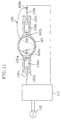
Patent Publication No.8-69777, for example. FIG. 11
shows a metal halide lamp having this configuration.
The metal halide lamp shown in FIG. 11 has an arc tube
101 and electrode sealing portions 102a and 102b, and a
trigger wire 108 having a first end 108a and a second end
108b is spirally wound around the circumference of the arc
tube 101. A pair of electrodes 103a and 103b are opposed to
each other inside the arc tube 101. The pair of electrodes
103a and 103b are connected to external lead wires 105a and
105b via the metal foils 104a and 104b in electrode sealing
portions 102a and 102b. The second end 108b of the trigger
wire 108 is connected to the external lead 105b, and the
first end 108a of the trigger wire 108 is wound around the
end (near the base) of the electrode sealing portion 102a on
the side of the arc tube 101. The external lead wires 105a
and 105b are electrically connected to an operating circuit
(driving device) 111, and the operating circuit 111 is
electrically connected to a power supply 107.
This metal halide lamp is provided with the trigger
wire 108, so that the breakdown voltage can be reduced. This
is caused by the following mechanism. When a high-voltage
pulse voltage is applied from the operation circuit 111
connected to the power supply 107 to the electrodes 103a and
103b, the trigger wire 108 has the same electric potential as
that of the electrode 103b. As a result, the trigger wire
108 causes an electrical field having a large electric
potential gradient to be formed inside the arc tube 101.
This electrical field is likely to cause insulation breakdown
of Xe gas between the electrodes 103a and 103b and thus the
breakdown voltage can be reduced.
However, in the case of the conventional metal halide
lamp provided with the trigger wire 108, although the
breakdown voltage can be reduced, color change, an increase
of the lamp voltage, or devitrification, which is a
phenomenon that the transparency is lost by opaqueness of the
arc tube, may occur during operation of the lamp.
Furthermore, the luminous flux maintenance factor is reduced,
or the lamp cannot be turned on, and thus the lifetime of the
lamp tends to be reduced.
As a result of the factors causing the above-described
phenomena in depth, the inventors of the present invention
found that the electrical field generated by the trigger wire
108 is a large factor. For example, in the case where a
driving voltage (lamp voltage) of 65V is applied across the
electrodes 103a and 103b during operation, the voltage
between the trigger wire 108 connected to the external lead
wire 105b and the electrode 103a is also 65V. When the
distance between the electrodes 103a and 103b is 3.7mm, the
shortest distance between the first end 108a of the trigger
wire 108 and the electrode 103a is 1mm, then the electric
potential gradient of the electrical field formed between the
electrodes 103a and 103b is 17.6V/mm. On the other hand, the
electric potential gradient of the electrical field formed
between the electrode 103a and the trigger wire 108 is 65V/mm,
which is more than three times higher than 17.6V/mm, in the
largest portion.
In the lamp where a high-voltage pulse voltage is
applied, the insulation breakdown of Xe gas is caused, and
thus discharge is started, the temperature of the inner wall
of the arc tube 101 is increased by subsequent discharge.
When the temperature of the inner wall of the arc tube 101 is
increased, enclosed material such as metal halide enclosed in
the arc tube 101 is evaporated and further ionized. The
ionized luminous material is affected more by the electrical
field between the trigger wire 108 and the electrode 103a
than by the electrical field between the electrodes 103a and
103b, and thus attracted more to the trigger wire 108. More
in details, in the case where the applied driving voltage is
alternating voltage, when the trigger wire 108 is in the
negative electric potential, the luminous material such as
sodium in the form of positive ions are attracted to the
trigger wire 108, and sodium having a small ion radius moves
in the quartz glass and leaks out of the arc tube 101. Thus,
the amount of the luminous material in the arc tube 101 is
reduced, so that the optical characteristics (color
temperature, lamp voltage, luminous flux maintenance factor
etc.) are significantly changed, which was found by the
inventor of the present invention. Furthermore, sodium or
the like breaks the amorphous structure of the quartz glass
while moving in the quartz glass, and crystallization of the
quartz glass (phase transition to cristobalite) occurs, which
causes opaqueness or devitrification of the quartz glass.
SUMMARY OF THE INVENTION
Therefore, with the foregoing in mind, it is a main
object of the present invention to prolong the lamp lifetime
of a high-intensity discharge lamp provided with the trigger
wire.
A high-intensity discharge lamp of the present
invention includes an arc tube including a pair of electrodes
opposed to each other therein; and a trigger wire made of a
conductive material provided in an outer circumference of the
arc tube. The trigger wire is turned to be in a conductive
state with one electrode of the pair of electrodes when a
start-up voltage is applied across the pair of electrodes,
and discharge is started between the pair of electrodes in a
state where an electrical field is formed between the trigger
wire that is in the conductive state and the other electrode
of the pair of electrodes.
In one embodiment of the present invention, a part of
the trigger wire is arranged close to an external lead wire
in an insulating state, the external lead wire being
electrically connected to the one electrode, and when the
start-up voltage is applied, insulation breakdown is caused
between the part of the trigger wire and the external lead
wire to establish the conductive state.
It is preferable that the part of the trigger wire is
arranged close to the external lead wire with a distance of
less than 3mm.
In one embodiment of the present invention, the part of
the trigger wire is insulated from the external lead wire
with air.
In one embodiment of the present invention, an
insulating tape is provided between the part of the trigger
wire and the external lead wire for insulation.
In one embodiment of the present invention, the high-intensity
discharge lamp further includes a pair of sealing
portions for sealing ends of the pair of electrodes, the
sealing portions extending from the arc tube, wherein the
trigger wire is wound around a region between the arc tube
and one of the pair of sealing portions that seals an end of
the other electrode.
It is preferable that the arc tube is made of quartz
glass.
In one embodiment of the present invention, a metal
halide is enclosed as a luminous material in the arc tube,
and the metal halide includes an alkaline metal halide.
In one embodiment of the present invention, the
alkaline metal halide is a sodium halide.
According to another aspect of the present invention, a
high-intensity discharge lamp operating apparatus includes a
high-intensity discharge lamp including an arc tube including
a pair of electrodes opposed to each other therein, and a
trigger wire made of a conductive material provided in an
outer circumference of the arc tube; an operating circuit for
operating the high-intensity discharge lamp. The trigger
wire is not electrically connected to either one of the pair
of electrodes. The operating circuit includes driving
voltage applying means for applying a driving voltage for
maintaining discharge after the discharge is started between
the pair of electrodes, and start-up voltage applying means
for applying a start-up voltage for starting discharge
between the pair of electrodes. The trigger wire is
electrically connected to the start-up voltage applying means,
and each of the pair of electrodes is electrically connected
to the driving voltage applying means.
In one embodiment of the present invention, the start-up
voltage applying means includes a timer for controlling
the start-up voltage applying means so as to apply the start-up
voltage to the trigger wire for a predetermined time
during start-up.
In one embodiment of the present invention, the start-up
voltage applying means includes detecting means for
detecting that lamp operation is started by discharge between
the pair of electrodes; and controlling means for stopping
application of the start-up voltage when the detecting means
detects that lamp operation is started.
In one embodiment of the present invention, the
detecting means is a voltage detector that detects a change
in voltage between the pair of electrodes.
In one embodiment of the present invention, the
detecting means is a current detector that detects a change
in current flowing between the pair of electrodes.
In one embodiment of the present invention, the high-intensity
discharge lamp further includes a pair of sealing
portions for sealing ends of the pair of electrodes, the
sealing portion extending from the arc tube, and the trigger
wire is wound around a region between one of the pair of
sealing portions and the arc tube.
It is preferable that the arc tube is made of quartz
glass.
In one embodiment of the present invention, the high-intensity
discharge lamp is a metal halide lamp in which a
metal halide including an alkaline metal halide is enclosed
as a luminous material in the arc tube.
In the present invention, when a start-up voltage is
applied across the pair of electrodes, the trigger wire is
turned to be in a conductive state with respect to one of the
electrodes. Therefore, the breakdown voltage can be lowered,
and changes in the characteristics of the lamp can be
prevented. As a result, the lamp lifetime of the high-intensity
discharge lamp provided with the trigger wire can
be prolonged. A part of the trigger wire is arranged close
to the external lead wire in an insulating state, so that
insulation breakdown is caused between the part of the
trigger wire and the external lead wire when a start-up
voltage is applied. With this simple configuration, the
effects of the present invention can be obtained.
Furthermore, in the case where a portion where the
trigger wire is wound around is provided in a region between
the sealing portion and the arc tube, the intensity of the
electrical field generated by the trigger wire can be large.
Therefore, with a comparatively low voltage, the high-intensity
discharge lamp can be started more reliably.
Furthermore, in the case where the arc tube is made of quartz
glass, quartz glass has a higher transmittance than that of
ceramic materials, and thus a point light source with which a
substantial emission region is small can be realized easily.
In addition, in the case where the metal halide enclosed in
the arc tube includes an alkaline metal halide, a high-intensity
discharge lamp (metal halide lamp) having emission
characteristics of high-intensity and excellent color
rendering properties can be realized easily.
According to the present invention, when a start-up
voltage is applied across the pair of electrodes, the trigger
wire is turned to be in a conductive state with respect to
one of the electrodes. Therefore, the breakdown voltage can
be lowered, and changes in the lamp characteristics can be
prevented. As a result, the lamp lifetime of the high-intensity
discharge lamp provided with the trigger wire can
be prolonged.
This and other advantages of the present invention will
become apparent to those skilled in the art upon reading and
understanding the following detailed description with
reference to the accompanying figures.
BRIEF DESCRIPTION OF THE DRAWINGS
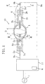
FIG. 1 is a cross-sectional view schematically showing
the configuration of a metal halide lamp of Embodiment 1
according to the present invention.
FIG. 2 is a cross-sectional view taken along line II-II
of FIG. 1.
FIG. 3 is a cross-sectional view taken along line III-III
of FIG. 1.
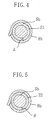
FIG. 4 is a cross-sectional enlarged view of a
principal portion of a variation of the metal halide lamp of
Embodiment 1.
FIG. 5 is a cross-sectional enlarged view of a
principal portion of a variation of the metal halide lamp of
Embodiment 1.
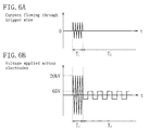
FIG. 6A is a graph schematically showing the waveform
of the current flowing the trigger wire.
FIG. 6B is a graph schematically showing the waveform
of the voltage applied to a pair of electrodes.
FIG. 7 is a view schematically showing the
configuration of a high-intensity discharge lamp operating
apparatus of Embodiment 2.
FIG. 8A is a graph schematically showing the waveform
of the current flowing the trigger wire.
FIG. 8B is a graph schematically showing the waveform
of the voltage applied to a pair of electrodes.
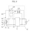
FIG. 9 is a view schematically showing the
configuration of a variation of the high-intensity discharge
lamp operating apparatus of Embodiment 2.
FIG. 10 is a view schematically showing the
configuration of a variation of the high-intensity discharge
lamp operating apparatus of Embodiment 2.
FIG. 11 is a cross-sectional view showing the
configuration of a conventional metal halide lamp.
DETAILED DESCRIPTION OF THE INVENTION
Hereinafter, embodiments of the present invention will
be described with reference to the accompanying drawings. In
the following drawings, for simplification, elements having
substantially the same function bear the same reference
numerals. The present invention is not limited to the
following embodiments.
Embodiment 1
A high-intensity discharge lamp of Embodiment 1
according to the present invention will be described with
reference to FIGS. 1 to 7. FIG. 1 is a schematic view of
cross-sectional configuration of a high-intensity discharge
lamp of this embodiment. FIG. 2 is cross-sectional view
taken along line II-II of FIG. 1, and FIG. 3 is cross-sectional
view taken along line III-III of FIG. 1.
A high-intensity discharge lamp 10 of this embodiment
is a metal halide lamp including a metal halide as the
luminous material. The metal halide lamp 10 shown in FIG. 1
includes an arc tube (luminous bulb) 1 in which a pair of
electrodes 3a and 3b are opposed to each other, and electrode
sealing portions 2a and 2b for sealing both ends of the arc
tube 1. A trigger wire 8 made of a conductive material (e.g.,
platinum wire) having a first end 8a and a second end 8b is
spirally wound around the circumferential surface of the arc
tube 1, and the first end 8a thereof is positioned near the
electrode 3a. The arc tube 1 in this embodiment is a
spheroidal transparent vessel made of quartz glass, and the
inside of the vessel constitutes a discharge space. The
outer diameter of the central portion of the arc tube 1 is
6.0mm, the thickness is 1.6mm, and the inner volume is
0.025cc.
In the arc tube 1, ScI3 (scandium iodide), NaI (sodium
iodide), InI3 (indium iodide), TlI (thallium iodide) as the
luminous materials and Xe gas with 1.4MPa as the start-up aid
gas are enclosed. However, unlike the configuration shown in
FIG. 11, Hg (mercury) is not enclosed in the arc tube 1 of
this embodiment. More specifically, the high-intensity
discharge lamp 10 of this embodiment is a so-called mercury-free
metal halide lamp. It is of course possible that it can
be used not only for a mercury-free metal halide lamp, but
also for a mercury-containing metal halide lamp enclosing
mercury. The start-up voltage tends to be higher in the
mercury-free metal halide lamp than in the mercury-containing
metal halide lamp. Therefore, it is more advantageous to
apply the configuration with the trigger wire 8 to the
mercury-free metal halide lamp. In other words, the effect
of the trigger wire 8 on the reduction in the start-up
voltage can be more significant. When constituting a metal
halide lamp not containing mercury, it is preferable that a
halide of indium (e.g., InI3 and/or InI, preferably InI3) is
contained as a metal halide in order to increase the lamp
voltage and lower the current for operating the lamp.
The metal halide lamp 10 emits light having an emission
spectrum in the visible light region because of light
emission of the metal halides in the arc tube 1. Although Na
of the NaI is a very preferable luminous material in that the
emission spectrum in a visible light region can be achieved,
an alkaline metal having a small ion radius such as Na tends
to move in the quartz glass and leak out of the arc tube in
the configuration of the conventional metal halide lamp
provided with a trigger wire (FIG. 11). In other words, in
the conventional metal halide lamp provided with a trigger
wire, it was difficult to use an alkaline metal halide as the
metal halide in view of the lamp lifetime.
The electrodes 3a and 3b provided in the arc tube 1 are
tungsten electrodes. The distance between the electrodes 3a
and 3b is set to, for example, 3.7mm. The pair of electrodes
3a and 3b are connected to external leads 5a and 5b via metal
foils 4a and 4b provided in electrode sealing portions 2a and
2b. In this embodiment, the electrodes sealing portions 2a
and 2b are formed of quartz glass and have a pinch seal
structure. The cross-sectional contour thereof is
substantially rectangular, as shown in FIG. 3. To obtain a
higher sealing pressure resistance, the electrode sealing
portions 2a and 2b can be of a shrink seal structure. In
that case, the cross-sectional contour is substantially
circular, for example.
The external lead wires 5a and 5b electrically
connected to the pair of electrodes 3a and 3b are
electrically connected to an operating circuit (driving
device) 11 including a ballast 6 via wires 9a and 9b. The
operating circuit 11 can output a high-voltage pulse voltage
(start-up voltage) for start-up and a driving voltage
(lighting operation voltage) for lighting operation, and is
electrically connected to a power supply 7. More in detail,
the operating circuit 11 outputs a high-voltage pulse voltage
for starting the lamp, and then controls the current flowing
through the metal halide lamp 10 so as not to flow at a
predetermined amount or more during operation. In this
embodiment, a high-voltage pulse voltage of 20kV is output
for a predetermined period that is preset by, for example, a
timer (not shown) to start the lamp, whereas during operation,
a voltage of 65V and a current of 0.54A are output at a
frequency of 150Hz, so that the metal halide lamp 10 is
turned on with a lamp power of 35W.
The trigger wire 8 is turned to be conductive with the
electrode 3b when the start-up voltage is applied across the
pair of electrodes 3a and 3b. In other words, the
relationship of the trigger wire 8 and the electrode 3b is
changed from an insulating state to a conductive state when
the start-up voltage is applied. In this embodiment, as
shown in FIG. 2, the second end 8b of the trigger wire 8 is
arranged close to the lead wire 5b in an insulating state
(air insulation), and air is present as an insulator between
the former and the latter (8b and 5b). This configuration
causes insulation breakdown between the second end 8b of the
trigger wire 8 and the lead wire 5b when a predetermined
voltage (high-voltage pulse voltage) is applied across the
external lead wire 5a and 5b from the operating circuit 11,
and thus the second end 8b and the lead wire 5b have the same
electric potential. In other words, only when the start-up
voltage is applied, the trigger wire 8 becomes conductive
with the electrode 3b via the external lead wire 5b. The
distance d between the second end 8b of the trigger wire 8
and the external wire 5b is for example, less than 3mm,
preferably about 1mm. The second end 8b of the trigger wire
8 can be spaced away from the external wire 5b, by fixing the
second end 8b of the trigger wire 8 to the external wire 5b
with, for example, an insulating fixing member.
Insulation can be achieved, not only by the air 20, but
also by keeping the gap between the second end 8b of the
trigger wire 8 and the external wire 5b in a vacuum state.
Furthermore, as shown in FIG. 4, an insulating tape 21 can be
wound around the external lead wire 5b. This configuration
makes it possible to adjust the distance d easily by the
number of winding of the tape 21. Furthermore, as shown in
FIG. 5, the external lead wire 5b can be covered with a
ceramic cylinder 22, and the second end 8b can be wound
around the outer circumference of the cylinder with about one
winding. In these cases, the distance d can be the same as
in the case of the air insulation.
The first end 8a of the trigger wire 8 is wound around
a region between the arc tube 1 and the sealing portion 2a,
as shown in FIG. 3. In other words, the metal halide lamp 10
has a winding portion 8a for the trigger wire 8 at the end
portion (near the base) of the sealing portion 2a on the arc
tube 1 side. In this embodiment, the first end 8a of the
trigger wire 8 and the electrode 3a sealed in the electrode
sealing portion 2a are closely positioned with a distance of
about 1mm (the shortest distance) via the quartz glass of
electrode sealing portion 2a.
Next, the operation of the metal halide lamp 10 of this
embodiment will be described with reference to FIGS. 6A and
6B. FIG. 6A is a graph schematically showing the waveform of
the current flowing the trigger wire 8. FIG. 6B is a graph
schematically showing the waveform of the voltage applied to
the pair of electrodes 3a and 3b.
First, during the start-up time (T1 ) of the lamp, a
high-voltage pulse voltage of 20kV is output from the
operating circuit 11 and applied across the electrodes 3a and
3b, as shown in FIG. 6B. The distance d between the external
lead wire 5b and the second end 8b of the trigger wire 8 is
comparatively short (e.g., about 1mm), so that when a high-voltage
pulse voltage is applied, insulation therebetween is
broken, and the trigger wire 8 has the same electric
potential as that of the electrode 3b, as shown in FIG. 6A.
Thus, an electrical field having a larger electric potential
gradient than that between the electrodes 3a and 3b occurs in
the vicinity between the first end 8a of the trigger wire 8
and the electrode 3a. Therefore, the insulation breakdown of
Xe gas in the arc tube 1 is facilitated, and insulation
breakdown readily occurs between the electrodes 3a and 3b.
As a result, the metal halide lamp is turned on (or discharge
is started) reliably.
This on-state is maintained stably once started, even
if the voltage is reduced. In other words, as shown in FIG.
6B, even if the output of the high pulse voltage from the
operating circuit 11 is stopped, and a voltage of 65V and a
current of 0.54A are output at a frequency of 150Hz (T2 ), the
on-state is maintained stably. On the other hand, as shown
in FIG. 6A, during the steady-state operation of the lamp
(T2 ), the electric potential of the trigger wire 8 is in a
floating state. In other words, in a state where a low
voltage during the steady-state operation of the lamp (T2 ) is
output from the operating circuit 11, insulation breakdown
does not occur between the second end 8b of the trigger wire
8 and the external lead wire 5b, and therefore, the second
end 8b and the external lead wire 5b are in an insulating
state, the electric potential of the trigger wire 8 is in a
floating state. Consequently, the trigger wire 8 hardly
affects the electrical field in the arc tube 1 during lamp
operation, and thus this embodiment prevents the luminous
material in the arc tube 1 from being attracted to the
trigger wire 8 and from leaking from the inside of the arc
tube 1.
In the configuration of this embodiment, the trigger
wire 8 (in particular, the first end 8a) is provided, so that
a comparatively low high-voltage pulse voltage of about 20kV
can start the metal halide lamp 10 reliably. Thus, the
compactness and the reduction of the production cost of the
operating circuit 11 can be achieved easily. In addition,
since the trigger wire 8 has the configuration as shown above
at the second end 8b, an electrical field due to the trigger
wire 8 does not occur during lamp operation. Therefore, the
leakage of the luminous material due to the influence of the
electrical field can be prevented. As a result, color change
due to the reduction of the luminous material or the increase
of the lamp voltage can be prevented. Thus, the metal halide
lamp 10 having stable characteristics and a long lifetime can
be realized.
Next, a high-voltage pulse voltage (breakdown voltage)
necessary to start the lamp will be described.
The inventors of the present invention measured the
breakdown voltage with respect to the metal halide lamp 10
provided with the trigger wire 8 of Embodiment 1 and a metal
halide lamp without the trigger wire 8. The metal halide
lamp without the trigger wire 8 has the same configuration as
that of the metal halide lamp 10 except that the trigger wire
8 is not provided.
The breakdown voltage was measured in the following
manner. In starting the operation of the metal halide lamps
by applying a high-voltage pulse voltage to the lamps, when
the breakdown occurs between the electrodes 3a and 3b to
start discharge, then the voltage across the electrodes 3a
and 3b is significantly dropped at the moment the lamp is
turned on. Using this phenomenon, the peak voltage at this
time was measured as the breakdown voltage necessary for
insulation breakdown. In the case where this measurement is
repeated, the metal halide lamp 10 is left undisturbed for 15
minutes or more after turned off, and then the lamp operation
is started again in the state where the lamp is sufficiently
cold in order to eliminate the influence of the temperature.
Table
1 shows the measurement results of the breakdown
voltage. In the case where the
trigger wire 8 is provided,
the distance
d between the
second end 8b and the
external
lead wire 5b is 1mm. Table
1 also shows the measurement
result of the metal halide lamp of Embodiment
2 described
later.
| Lamps for measurement | Breakdown voltage (kV) |
| Metal halide lamp of Embodiment 1 | 12.3 |
| Metal halide lamp of Embodiment 2 | 12.2 |
| Metal halide lamp without trigger wire | 20.8 |
As shown in Table 1, the breakdown voltage of the metal
halide lamp without the trigger wire 8 is 20.8kV, the
breakdown voltage of the metal halide lamp provided with the
trigger wire 8 is 12.3kV, which is significantly reduced.
With a breakdown voltage of about 15kV or less, the lamp can
be started reliably under commonly used conditions.
Considering about ±30% variations due to the ambient
temperature of the lamp and the ballast, the temperature of
the lamp itself, the position of the metal halide
(concentration distribution) in the arc tube and the state of
the electrodes, a high-voltage pulse voltage of about 20kV or
less only needs to be applied from the operating circuit 11.
The operating circuit 11 generating a high-voltage pulse
voltage of about 20kV or less can easily achieve compactness
and low cost of the circuit, and can provide high utility in
the current market.
In the case of the metal halide lamp without the
trigger wire 8, the measured breakdown voltage is 20.8kV, and
therefore it is necessary to apply a high-voltage pulse
voltage exceeding 20kV. An operating circuit generating such
a high high-voltage pulse voltage has to be produced in a
special specification, and the circuit configuration becomes
large-scale because components having a high withstand
voltage are used, thus leading to high cost. Therefore, such
a metal halide lamp has low utility in the market.
Next, the distance between the
second end 8b of the
trigger wire 8 and the
external lead wire 5b will be
described. The inventors of the present invention conducted
a test as follows. The distance
d (shortest distance)
between the
second end 8b of the
trigger wire 8 and the
external lead wire 5b in the
metal halide lamp 10 of this
embodiment is set to various values in the range from 0.5mm
to 4mm, and a high-voltage pulse voltage of 15kV is applied
to start the lamp in the same manner as described above.
Table
2 shows the results of the test to start the lamp.
This test was conducted with the configuration where the
insulating
tape 21 is provided as shown in FIG.
4.
Distance d
(mm) | 0.5 | 1.0 | 1.5 | 2.0 | 2.5 | 3.0 | 3.5 | 4.0 |
| Starting Test results | G | G | G | G | G | N | N | N |
As shown in Table 2, when the distance d between the
second end 8b of the trigger wire 8 and the external lead
wire 5b was less than 3mm (e.g., 2.5mm to 0.5mm), the lamp
was turned on reliably. However, in the case of 3mm or more,
the lamp was not turned on. The reason why the lamp was not
turned on seems be that when the distance d is large,
insulation breakdown does not occur, so that the electric
potential of the trigger wire 8 is not the same as that of
the external lead wire 5b. In general and regular lamps, by
setting the distance d to less than 3mm, the start-up
properties can be satisfactory. However, the distance d is
not limited thereto, and can be set as appropriate, depending
on various conditions. For example, depending on the
arrangement of the trigger wire 8, the type of the insulator,
the distance between the electrodes 3a and 3b, the applied
voltage or the like, the distance d can be set suitably such
that insulation breakdown occurs only when a high-voltage
pulse voltage is applied.
The second end 8b of the trigger wire 8 is not
necessarily disposed close to the external lead wire 5b, but
can be disposed close to a portion to which a high voltage
for starting the lamp is applied, such as a wire 9b.
Furthermore, the end of the trigger wire 8 is not necessarily
disposed close to the external lead wire 5b, but the other
portions such as the center of the trigger can be disposed
close thereto.
Next, the lifetime of the lamp will be described. The
inventors of the present invention conducted a test regarding
the lamp lifetime with respect to the metal halide lamp
10
(see FIG.
1) of this embodiment where the
second end 8b of
the
trigger wire 8 is disposed close to the
external lead
wire 5b and a metal halide lamp where the
trigger wire 108 is
connected to one of the
external lead wires 105b, and has the
same electric potential as that of one of the
electrodes 103b
constantly, even during lamp operation (Comparative Example;
see FIG.
11 regarding the configuration of the trigger wire
108). The constitutions of the enclosed materials are the
same in the two lamps. In the lifetime test, the influence
of the trigger wire was examined with the two lamps that has
been on for 250 hours. Table
3 shows the results of the
lifetime test. Table
3 shows a typical example of ten tests
of each lamp.
| | change after initial test |
| Lamps for measurement | Color temperature (K) | Lamp voltage (V) | Luminous flux maintenance factor (%) | Devitrification |
| Metal halide lamp | 4000 →4300 | 67 →67 | 98 | Not observed |
| Comparative Example | 4000 →6500 | 60 →120 | 50 | Observed |
As shown in Table 3, in the metal halide lamp of
Comparative Example, a large change in the color temperature
(4000K to 6500K) was observed after 250 hours operation, and
the lamp voltage was increased (from 60V to 120V). The lamp
that has been widely changed in color, that is, from 4000K to
6500K in the color temperature, is turned to be a defective
lamp that cannot be used for a headlight of automobiles.
Furthermore, the devitrification phenomenon that the arc tube
becomes opaque and the transparency is lost was observed.
Furthermore, the luminous flux maintenance factor was reduced
to 50%.
Such significant degradation in the performance occurs
in the conventional configuration, presumably because the
electric potential of the trigger wire 108 is the same as
that of the electrode 103b. In other words, during lamp
operation, the trigger wire 108 has the same electric
potential as that of the electrode 103b, and therefore an
electric potential having a large electric potential gradient
is formed between the first end 108a of the trigger wire 108
and the electrode 103a. Therefore, the ionized luminous
material in the arc tube is attracted to the trigger wire 108,
and especially sodium, which has a small ion radius and can
move in the quartz glass, leaks out of the arc tube 101. As
a result, significant degradation occurs. Furthermore, since
the amorphous structure of the quartz glass is broken while
sodium or the like is moving in the quartz glass, opaqueness
and devitrification of the quartz glass are caused.
On the other hand, in the metal halide lamp 10 of this
embodiment, the electric potential of the trigger wire 8 is
in a floating state during lamp operation. Therefore, an
electrical field having a large electric potential gradient
is not formed, so that the luminous material does not leak
out. As a result, the change in the color temperature, the
increase in the lamp voltage and the reduction in the
luminous flux maintenance factor hardly occur, and
devitrification does not occur in the arc tube 1.
Consequently, a long lifetime of the lamp can be achieved.
In this embodiment, when a start-up voltage is applied,
the insulating state between the trigger wire 8 and the
electrode 3b is changed to the conductive state. Therefore,
the breakdown voltage can be lowered, and the change in the
lamp characteristics can be prevented. As a result, the
metal halide lamp 10 having a long lamp lifetime can be
provided. More in detail, discharge readily occurs between
the pair of electrodes 3a and 3b by the influence of the
electrical field formed between the trigger wire 8 and the
electrode 3a by establishing the conductive state between the
trigger wire 8 and the electrode 3b during the start-up.
Therefore, a comparatively low voltage easily can start the
lamp operation. In addition, the trigger wire 8 and the
electrode 3b is in the conductive state only during the
start-up, and during operation, a large electrical field does
not occur in the vicinity of the trigger wire 8.
Consequently, the ionized material (e.g., sodium ions)
enclosed in the arc tube 1 is not attracted to the trigger
wire 8, does not move inside the bulb wall of the arc tube 1
nor leaks out. Therefore, the amount of the enclosed
material is not reduced, or the amorphous structure is not
broken, which might occur when ions are moving inside the
bulb wall of the arc tube. Therefore, the change in the
color temperature, the increase in the lamp voltage, the
reduction in the luminous flux maintenance factor, the
devitrification of the arc tube are not caused and a long
lifetime of the lamp can be achieved.
Furthermore, in this embodiment, when the trigger wire
8 is provided with a close portion (8b) to the external lead
wire 5b, and a start-up voltage (high-voltage pulse voltage)
is applied during the start-up, then a high voltage is
applied to the trigger wire 8 because of insulation breakdown.
Therefore with a simple configuration, the reduction of the
breakdown voltage and the effect of prevention of the lamp
characteristics change can be obtained.
In order to apply a high voltage to the trigger wire 8,
not only the configuration utilizing insulation breakdown,
but also for example, a configuration using a switching
element such as bimetal can be used. In other words, a
switching element can be used to connect the trigger wire 8
to a high voltage power supply only during the start-up.
However, in the case where bimetal is used, the
temperature of the lamp before operation may prevent
satisfactory switching operation when turning on the lamp
again. Therefore, in addition to the advantage of simple
configuration, also in view of reliable operation, the above
configuration using insulation breakdown is highly
advantageous. In this embodiment, the electric potential of
the trigger wire 8 is the same as that of the electrode 3b
during the start-up. However, the present invention is not
limited thereto, and the electric potential of the trigger
wire 8 is not necessarily the same as that of the electrode
3b. Any electric potential can be used as long as it can
start discharge between the electrodes 3a and 3b by the
electrical field formed between the first end 8a and the
electrode 3a.
Embodiment 2
Embodiment 2 of the present invention will be described
with reference to FIGS. 7 and 8. FIG. 7 schematically shows
the circuit configuration of a high-intensity discharge lamp
operating apparatus of the present invention.
The high-intensity discharge lamp operating apparatus
shown in FIG. 7 includes a metal halide lamp 13 and an
operating circuit 12 for operating the metal halide lamp 13.
In the configuration of this embodiment as in Embodiment 1, a
high-voltage pulse voltage is applied to the trigger wire 8
wound around the lamp 13 only during the start-up. However,
this embodiment is different from Embodiment 1 in that a
high-voltage pulse voltage for the start-up is applied only
to the trigger wire 8, and the same voltage (driving voltage)
as during operation is applied across the pair of electrodes
3a and 3b of the lamp during the start-up. Furthermore, this
embodiment is different in that application of a high-voltage
pulse voltage is achieved not by the insulation breakdown
from the external lead wire 5b, but the control by the
operating circuit (driving circuit) 12. Other aspects are
the same as in Embodiment 1, so that description thereof will
be omitted or simplified.
The operating circuit 12 shown in FIG. 7 is different
from the operating circuit 11 of Embodiment 1 in that the
driving voltage for operating the lamp is output
independently of the high-voltage pulse voltage for starting
the lamp operation. In other words, the voltage for
operating the lamp is output from the power supply 7 via a
ballast 6 of the operating circuit 12. On the other hand,
for the high-voltage pulse voltage for starting the lamp
operation, the voltage of the power supply 7 is increased by
a step-up transformer 130, and output via a relay 120. The
relay 120 is controlled by a timer circuit 110 so as to be on
for a predetermined time (e.g., one second) after the start
of the start-up operation.
The metal halide lamp 13 is provided with the trigger
wire 8 whose first end 8a is wound around the base of the
electrode sealing portion 2a, as in the metal halide lamp 10
of Embodiment 1. However, the second end 8b of the trigger
wire 8 is not provided close to the external lead wire 5b,
but is electrically connected to the relay 120 of the
operating circuit 12 via a wire 100. Furthermore, the
external lead wire 5a and 5b are electrically connected to
the ballast 6 of the operating circuit 12.
Next, the operation of this embodiment will be
described also with reference to FIG. 8. FIG. 8A is a graph
schematically showing the waveform of the voltage applied to
the trigger wire 8. FIG. 8B is a graph schematically showing
the waveform of the voltage applied across the pair of
electrodes 3a and 3b.
As shown in FIGS. 8A and 8B, during the start-up of the
lamp (T1 ), in the state where the driving voltage (e.g., 65V)
output from the ballast 6 is applied across the external lead
wires 5a and 5b, a high-voltage pulse voltage (e.g., 20kV)
output from the step-up transformer 130 is applied to the
trigger wire 8. Thus, an electrical field having a large
electric potential gradient occurs in the vicinity of the
first end 8a of the trigger 8 inside the arc tube 1, and the
insulation breakdown of Xe gas is facilitated. Therefore,
with a lower start-up voltage, discharge is started with the
driving voltage applied across the external lead wires 5a and
5b, and thus the lamp is turned on.
When one second has passed since a start-up operation
is started, the relay 120 is turned off by the control of the
timer circuit 110, so that the electric potential of the
trigger wire 8 is in a floating state (T2 ). Therefore, as in
Embodiment 1, an electrical field having a large electric
potential is not formed between the trigger wire 8 and the
discharge electrode during operation, so that the luminous
material does not leak out. Consequently, the change in the
color temperature, the increase in the lamp voltage and the
reduction in the luminous flux maintenance factor hardly
occur, and devitrification does not occur in the arc tube 1.
Consequently, a long lifetime of the lamp can be achieved.
Furthermore, in the configuration of this embodiment, a high-voltage
pulse voltage is not applied across the pair of
electrodes 3a and 3b, so that damages such as depletion due
to melt deformation or evaporation of the electrode during
the start-up can be prevented or reduced.
For the metal halide lamp 13 of this embodiment, the
breakdown voltage was measured in the same manner as in
Embodiment 1. As shown in Table 1, the breakdown voltage was
12.2V. In other words, compared to the metal halide lamp
without the trigger wire, the breakdown voltage can be
reduced significantly. Furthermore, when the lifetime test
was carried out, as in the metal halide lamp 10 of the
Embodiment 1, the phenomenon that an alkaline metal such as
sodium as the luminous material leaks out of the arc tube 1
was not observed, and it was found that stable
characteristics and a long lamp lifetime can be obtained.
The configuration shown in FIG. 7 can be modified to
the configuration shown in FIG. 9. FIG. 9 shows the circuit
configuration of a variation of Embodiment 2.
In the configuration shown in FIG. 9, the control of
the relay 120 for applying a high-voltage pulse voltage only
during the start-up is performed by operation detecting means
150 for detecting that the lamp is turned on, instead of the
timer circuit 110. As the operation detecting means 150, for
example, a current detector for detecting the lamp current
can be used. Describing the operation more specifically,
discharge between the discharge electrodes is started by
applying a high-voltage pulse voltage to the trigger wire 8.
Then, for example, when a lamp current of 0.3A or more is
detected by the current detector 150, the relay 120 is turned
off, so that a high-voltage pulse voltage is not applied to
the trigger wire 8.
Furthermore, as shown in FIG. 10, the operating circuit
15 can be configured such that a voltage detector 151 for
detecting the lamp voltage is used as the operation detecting
means to control the relay 120. When the discharge is not
started between the discharge electrodes, the output voltage
from the ballast 6 is a predetermined open circuit voltage
(e.g., 350V), and when discharge is started, the lamp voltage
is for example, about 65V. Utilizing this change in the
voltage to detect that the lamp operation is started, a high-voltage
pulse voltage can be applied to the trigger wire 8
only during the start-up. Furthermore, in order to detect
that the lamp operation is started, an optical sensor can be
used.
In the above embodiments, the arc tube 1 is made of
quartz glass, but the present invention is not limited
thereto and the arc tube made of a ceramics materials can be
used. However, compared to the arc tube made of quartz glass,
the arc tube made of a ceramic material is, so-called obscure
glass, so that a point light source is difficult to achieve.
In other words, for ceramic arc tubes of obscure glass, the
entire of the arc tube is luminous, so that it is difficult
to obtain a point light source. Therefore, it is preferable
to use the arc tube made of quartz glass for applications
requiring a point light source such as a headlight of
automobiles.
Furthermore, the present invention has been described
by taking the metal halide lamp as an example, but is not
limited thereto, and the present invention can be applied to
various high-intensity discharge lamp (e.g., high pressure
mercury lamp) having a similar discharge mechanism. In other
words, from the viewpoint that the leakage of the luminous
material such as sodium can be prevented, the advantage is
large when the present invention is applied to metal halide
lamps, but the present invention can be applied suitably to
other high-intensity discharge lamps (HID) such as high
pressure mercury lamps, high pressure sodium lamps or the
like.
The xenon gas pressure, the inner volume of the arc
tube 1, the distance between the electrodes, a combination of
metal halides such as scandium iodide and sodium iodide in
the above embodiments are only illustrative. Therefore, for
example, the inner volume of the arc tube 1 is not limited to
0.025cc, or the distance between the electrodes is not
limited to 3.7mm. Other combinations of metal halides can be
used. Xenon gas is enclosed in the arc tube 1 for the
purpose of aiding to start the lamp operation in the above
embodiments. However, xenon gas is suitable as a rare gas
only in the viewpoint of an application to a headlight of
automobiles, but other rare gases than xenon, for example,
argon gas can be used. Similarly, the lamp power is not
limited to 35W. The high-intensity discharge lamp in the
above embodiments can be used not only for a headlight for
automobiles, but for general illumination or other
applications. For example, the present invention can be used
as a light source for image projecting apparatus such as
projectors using liquid crystal or a DMD. Furthermore, the
present invention can also be used for sports stadiums or
floodlights illuminating road signs.
The invention may be embodied in other forms without
departing from the spirit or essential characteristics
thereof. The embodiments disclosed in this application are
to be considered in all respects as illustrative and not
limiting. The scope of the invention is indicated by the
appended claims rather than by the foregoing description, and
all changes which come within the meaning and range of
equivalency of the claims are intended to be embraced therein.