EP1162726A1 - Dynamic brake circuit and semiconductor inverter using dynamic brake circuit - Google Patents
Dynamic brake circuit and semiconductor inverter using dynamic brake circuit Download PDFInfo
- Publication number
- EP1162726A1 EP1162726A1 EP00908038A EP00908038A EP1162726A1 EP 1162726 A1 EP1162726 A1 EP 1162726A1 EP 00908038 A EP00908038 A EP 00908038A EP 00908038 A EP00908038 A EP 00908038A EP 1162726 A1 EP1162726 A1 EP 1162726A1
- Authority
- EP
- European Patent Office
- Prior art keywords
- circuit
- inverter
- semiconductor
- semiconductor switching
- resistor
- Prior art date
- Legal status (The legal status is an assumption and is not a legal conclusion. Google has not performed a legal analysis and makes no representation as to the accuracy of the status listed.)
- Withdrawn
Links
Images



Classifications
-
- B—PERFORMING OPERATIONS; TRANSPORTING
- B60—VEHICLES IN GENERAL
- B60L—PROPULSION OF ELECTRICALLY-PROPELLED VEHICLES; SUPPLYING ELECTRIC POWER FOR AUXILIARY EQUIPMENT OF ELECTRICALLY-PROPELLED VEHICLES; ELECTRODYNAMIC BRAKE SYSTEMS FOR VEHICLES IN GENERAL; MAGNETIC SUSPENSION OR LEVITATION FOR VEHICLES; MONITORING OPERATING VARIABLES OF ELECTRICALLY-PROPELLED VEHICLES; ELECTRIC SAFETY DEVICES FOR ELECTRICALLY-PROPELLED VEHICLES
- B60L7/00—Electrodynamic brake systems for vehicles in general
- B60L7/003—Dynamic electric braking by short circuiting the motor
-
- B—PERFORMING OPERATIONS; TRANSPORTING
- B60—VEHICLES IN GENERAL
- B60L—PROPULSION OF ELECTRICALLY-PROPELLED VEHICLES; SUPPLYING ELECTRIC POWER FOR AUXILIARY EQUIPMENT OF ELECTRICALLY-PROPELLED VEHICLES; ELECTRODYNAMIC BRAKE SYSTEMS FOR VEHICLES IN GENERAL; MAGNETIC SUSPENSION OR LEVITATION FOR VEHICLES; MONITORING OPERATING VARIABLES OF ELECTRICALLY-PROPELLED VEHICLES; ELECTRIC SAFETY DEVICES FOR ELECTRICALLY-PROPELLED VEHICLES
- B60L7/00—Electrodynamic brake systems for vehicles in general
- B60L7/02—Dynamic electric resistor braking
- B60L7/06—Dynamic electric resistor braking for vehicles propelled by AC motors
-
- H—ELECTRICITY
- H02—GENERATION; CONVERSION OR DISTRIBUTION OF ELECTRIC POWER
- H02P—CONTROL OR REGULATION OF ELECTRIC MOTORS, ELECTRIC GENERATORS OR DYNAMO-ELECTRIC CONVERTERS; CONTROLLING TRANSFORMERS, REACTORS OR CHOKE COILS
- H02P3/00—Arrangements for stopping or slowing electric motors, generators, or dynamo-electric converters
- H02P3/06—Arrangements for stopping or slowing electric motors, generators, or dynamo-electric converters for stopping or slowing an individual dynamo-electric motor or dynamo-electric converter
- H02P3/18—Arrangements for stopping or slowing electric motors, generators, or dynamo-electric converters for stopping or slowing an individual dynamo-electric motor or dynamo-electric converter for stopping or slowing an AC motor
- H02P3/22—Arrangements for stopping or slowing electric motors, generators, or dynamo-electric converters for stopping or slowing an individual dynamo-electric motor or dynamo-electric converter for stopping or slowing an AC motor by short-circuit or resistive braking
-
- H—ELECTRICITY
- H02—GENERATION; CONVERSION OR DISTRIBUTION OF ELECTRIC POWER
- H02P—CONTROL OR REGULATION OF ELECTRIC MOTORS, ELECTRIC GENERATORS OR DYNAMO-ELECTRIC CONVERTERS; CONTROLLING TRANSFORMERS, REACTORS OR CHOKE COILS
- H02P6/00—Arrangements for controlling synchronous motors or other dynamo-electric motors using electronic commutation dependent on the rotor position; Electronic commutators therefor
- H02P6/24—Arrangements for stopping
-
- Y—GENERAL TAGGING OF NEW TECHNOLOGICAL DEVELOPMENTS; GENERAL TAGGING OF CROSS-SECTIONAL TECHNOLOGIES SPANNING OVER SEVERAL SECTIONS OF THE IPC; TECHNICAL SUBJECTS COVERED BY FORMER USPC CROSS-REFERENCE ART COLLECTIONS [XRACs] AND DIGESTS
- Y02—TECHNOLOGIES OR APPLICATIONS FOR MITIGATION OR ADAPTATION AGAINST CLIMATE CHANGE
- Y02T—CLIMATE CHANGE MITIGATION TECHNOLOGIES RELATED TO TRANSPORTATION
- Y02T10/00—Road transport of goods or passengers
- Y02T10/60—Other road transportation technologies with climate change mitigation effect
- Y02T10/64—Electric machine technologies in electromobility
Definitions
- the present invention relates to prevention of erroneous operations of a dynamic brake circuit of a motor to be driven by an inverter comprised of semiconductor switching devices.
- inverter drive motors which are represented by permanent magnet synchronous motors
- dynamic brake To stop inverter drive motors, which are represented by permanent magnet synchronous motors, in a case of emergency, a method called “dynamic brake” has been employed in which the operation of the inverter is stopped, power generated from the power supply lines of the motor that rotates under inertia is short-circuited with a brake resistor and consumed as heat energy, and the energy is absorbed for braking.
- Fig. 5 is a circuit diagram of a conventional brake for an inverter drive motor.
- a series circuit which consists of a three-phase bridge rectifier circuit including diodes 33 connected to the power supply lines 32, thyristor 34 as a semiconductor braking switch, and brake resistor 35.
- a snubber circuit in which snubber resistor 36 and snubber capacitor 37 are connected in series is connected to this thyristor 34 in parallel.
- ignition current limiting resistor 38, photocoupler 39 consisting of a photodiode and a photothyristor, bias capacitor 40,. and bias resistor 41 comprise an ignition control circuit of the thyristor 34.
- the capacitance of the snubber circuit must be made sufficient to suppress the rate of voltage change dv/dt, or a semiconductor braking switch with a sufficiently great critical OFF voltage rise rate must be selected. Therefore, the circuit becomes large and complicated, and cost for the parts increases.
- the object of the invention is to provide a safe brake for an inverter drive motor in which the rate of voltage change dv/dt generated by the operation of the semiconductor switching devices of the inverter is not directly applied to the semiconductor braking switch.
- a dynamic brake circuit which comprises a series circuit including resistors for converting loaded electric energy into heat and semiconductor switching devices, which are connected in series, and a snubber circuit including a capacitor connected in parallel to the semiconductor switching devices, further comprises a charging circuit for charging electricity in the capacitor prior to driving to load.
- a semiconductor inverter which comprises a first rectifier for rectifying alternating currents, a smoother for smoothing the output of the first rectifier, and an inverter part for switching the output from the smoother at a desired timing by the first semiconductor switching device, and further comprises a dynamic brake circuit consisting of a second rectifier for rectifying the output from the inverter part and a series circuit including the first resistance and second semiconductor switching device that are connected between the output terminals of the second rectifier, and a snubber circuit including a capacitor connected in parallel to the second semiconductor switching device, the inverter is provided with a charging circuit for charging electricity in the capacitor before the inverter starts an inverter operation.
- the charging circuit is comprised of a second resistance connected between the anode side of the smoother and anode side of the dynamic brake circuit, and a third switching device.
- a part of the first semiconductor switching devices is commonly used.
- the flywheel diodes are commonly used in place of the diodes comprising one arm of the second rectifier.
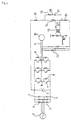
- Fig. 1 is a circuit diagram showing an embodiment of a semiconductor inverter with a dynamic brake circuit according to the invention
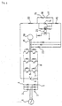
- Fig. 2 is a drawing showing a semiconductor inverter having a thyristor ignition circuit that is different from Fig. 1
- Fig. 3 is a circuit diagram showing a modified example of Fig. 1
- Fig. 4 is a circuit diagram showing a modified example of Fig. 2
- Fig. 5 is a circuit diagram of a conventional inverter.
- Fig. 1 through Fig. 4 are circuit diagrams showing an example in which a charging circuit for charging snubber capacitor 17 of snubber circuit 18.
- the anode and cathode of smoothing capacitor 6 are connected to anode 4 and cathode 5 at the output of bridge circuit 3 in which six diodes 2 are connected to three-phase AC power supply 1.
- Three pairs of semiconductor switching devices 7 such as thyristors, transistors or the like, each two of which are connected in series, are connected in parallel to the smoothing capacitor 6 to form an inverter part.
- Flywheel diodes 8 are connected in antiparallel to the semiconductor switching devices 7, and the intermediate connecting points 9 of the semiconductor switching devices 7 are formed as output points of each phase, and to these points, power supply lines 11 of each phase of motor 10 are connected.
- the phase of the motor 10 is controlled with characteristics corresponding to the switching timings of the semiconductor switching devices 7.
- a dynamic brake circuit in which three-phase bridge circuit 13 including diodes 12 connected to the power supply lines 11, thyristor 14 as a semiconductor braking switch, and brake resistor 15 are connected in series.
- snubber circuit 18 including snubber resistor 16 and snubber capacitor 17 connected in series is connected in parallel to the thyristor 14. To the gate electrode of the thyristor 14, an ignition circuit using a pulse transformer is connected.
- Charging circuit 21 comprised of charging resistor 20 with a high ohmic value is connected between the anode side of the thyristor 14 and the anode side of the smoothing capacitor 6.
- any of the semiconductor switching devices 7 of the negative side arm of the inverter part may be ignited.
- a closed charging circuit is formed from the anode of the smoothing capacitor 6, charging resistor 20 of the charging circuit 21, snubber resistor 16 of the snubber circuit 18, snubber capacitor 17, brake resistor 15, the negative side arm diode of the three-phase bridge circuit 13, power supply lines 11, semiconductor switching devices 7 to the cathode of the smoothing capacitor 6, and charges in the smoothing capacitor 6 are charged in the snubber capacitor 17.
- the voltage at both ends of the snubber capacitor 17, that is, the voltage at both ends of the thyristor 14 after charging is finished becomes equal to the voltage of the smoothing capacitor 6.
- ⁇ (t) (R15+R16+R20) x C17
- the snubber capacitor 17 is charged in the condition where an extreme rate of voltage change dv/dt is suppressed by the charging resistor 20 with a high ohmic value and the time constant of the snubber capacitor 17, and even if the inverter operation is started after the snubber capacitor 17 is charged, since the same voltage as that of the smoothing capacitor 6 as an input of the inverter part has already been charged in the snubber capacitor 17, dv/dt due to switching of the transistors comprising the inverter part is not applied at all to the thyristor 14 that functions as a switch of the dynamic brake circuit, and therefore, erroneous ignition of the thyristor 14 is prevented.
- the snubber circuit 18 can be simplified to be small in capacitance.
- thyristors are used in this embodiment, however, they are not limited to thyristors, but may be mechanical switches (for example, relays) as well as triacs, transistors, or the like.
- switches for example, relays
- triacs triacs
- transistors or the like.
- currents are flown into a pulse transformer or relay coil as well as a photocoupler.
- the resistors provided in the charging circuit may be disposed at any locations within the circuit, and if the charging period of time is adjustable by control of the current by means of the charging means, the resistors are not necessary.
- the transistor (first semiconductor switching devices) of the inverter part is commonly used as a charging circuit opening and closing switch, however, as a matter of course, a third switching device exclusively for opening and closing the charging circuit may be externally and separately provided.
- Fig. 2 shows an example of a case where the ignition circuit of the example shown in Fig. 1 is changed.
- the anode and cathode of the smoothing capacitor 6 are connected to the anode 4 and cathode 5 at the outputs of the bridge circuit in which six diodes 2 are connected to the three-phase AC power supply 1.
- Three pairs of semiconductor switching devices 7, each two of which are connected in series, are connected in parallel to the smoothing capacitor 6 to form an inverter part.
- Flywheel diodes 8 are connected to the semiconductor switching devices 7, respectively, and the intermediate connecting points 9 of the semiconductor switching devices 7 are formed as output points of each phase, and to the points, the power supply lines 11 of each phase of the motor 10 are connected.
- the phase of the motor 10 is controlled by characteristics corresponding to the switching timings of the semiconductor switching devices 7.
- a dynamic brake circuit in which three-phase bridge circuit 13 having diodes 12 connected to the power supply lines 11, thyristor 14, and brake resistor 15 are connected in series.
- An ignition circuit using photocoupler 22 consisting of a pair of phototransistor and photothyristor is connected to the gate electrode of the thyristor 14. They photocoupler 22 is employed for electric insulation upon replacing the signals at the ignition power supply side with a low voltage and at the thyristor side with a high voltage by light.
- Charging circuit 21 comprised of charging resistor 20 with a high ohmic value relating to the invention is connected between the anode side of the thyristor 14 and the anode side of the smoothing capacitor 6. Thereby, the snubber capacitor 17 is always charged in advance of operation of the inverter part.
- any of the semiconductor switching devices 7 of the negative side arm of the inverter part may be ignited. Then, a closed charging circuit is formed from the anode of the smoothing capacitor 6, charging resistor 20 of the charging circuit 21, snubber resistor 16 of the snubber circuit 18, snubber capacitor 17, brake resistor 15, negative side arm diode of the three-phase bridge circuit 13, power supply lines 11, and semiconductor switching devices 7 to the cathode of the smoothing capacitor 6, whereby charges in the smoothing capacitor 6 are charged in the snubber capacitor 17.
- the voltage at both ends of the snubber capacitor 17, that is, the voltage at both ends of the thyristor 14 after charging is finished becomes equal to the voltage of the smoothing capacitor 6.
- the snubber capacitor 17 is charged in a condition where an extreme rate of voltage change dv/dt is suppressed by the charging resistor 20 with a high ohmic value and the time constant of the snubber capacitor 17, and even when the inverter operation is started after the snubber capacitor 17 is charged, since the same voltage as that of the smoothing capacitor 6 as the input of the inverter part has already been charged in the snubber capacitor 17, dv/dt due to switching of the transistors comprising the inverter part is not applied at all to the thyristor 14, which functions as a switch for the dynamic brake circuit, and the photothyristor 22 at all.
- the snubber circuit 18 can be simplified to be small in capacitance.
- Fig. 3 shows a circuit constructed so that devices of the generation brake circuit and devices of the energy absorbing circuit of the motor power supply lines are commonly used.
- the anode and cathode of the smoothing capacitor 6 are connected to the anode 4 and cathode 5 at the output of the bridge circuit 3 in which six diodes 2 are connected to the three-phase AC power supply 1, three pairs of semiconductor switching devices 7 such as transistors, each two of which are connected in series, are connected in parallel to the smoothing capacitor 6 to form an inverter part, flywheel diodes 8 are connected in antiparallel to the semiconductor switching devices 7, the intermediate connecting points 9 of the semiconductor switching devices 7 are formed as output points of each phase, and the points to which power supply lines 11 of each phase of the motor 10 are connected are the same in the case of Fig. 1 and Fig. 2.
- charging resistor 20 one end of which is connected to the anode side of the smoothing capacitor 6, thyristor 14 anode side of which is connected to the other end of the charging resistor 20, brake resistor 15 one end of which is connected to the cathode side of the thyristor 14, and three diodes 23, anode sides of which are connected to the other end of the brake resistor 15 and cathode sides of which are connected to the power supply lines 11 of each phase of the motor, are provided, and an ignition circuit using pulse transformer 19 is connected to the gate electrode of the thyristor 14.
- the diode group 12 of the anode side arm of the second rectifier 13 of Fig. 1 is replaced with the flywheel diodes 8 of the first semiconductor switching devices 7 of the anode side arm, and this contributes to reduction in size and cost.
- the snubber capacitor 17 is always charged via the charging resistor 20 to suppress dv/dt of the inverter part, and the diodes 23 prevent direct entrance of dv/dt from the inverter part, so that short-circuiting failures due to the dynamic brake circuit do not occur during the inverter operation.
- Fig. 4 shows an example in which photocoupler 22 comprised of a photodiode and a photothyristor is used for the ignition circuit of the thyristor 14 of the circuit of Fig. 3 in place of the circuit using the pulse transformer 19, wherein other points in construction are the same, so that explanation for the points is omitted by attaching the same symbols as those of Fig. 3 to the same points.
- a brake constructed so that, when braking an inverter drive motor, which is driven by switching outputs of a current obtained through rectification of an alternating current and smoothing by a smoothing capacitor, a semiconductor braking switch is ignited, the power supply lines of the motor are short-circuited, and energy is absorbed by a brake resistor, a charging circuit for always charging a snubber capacitor is provided between the anode side of the smoothing capacitor and the anode side of the semiconductor braking switch, whereby the voltage change dv/dt of the inverter part is not applied to the semiconductor braking switch, so that erroneous operations of the semiconductor braking switch can be prevented.
- the snubber circuit can be simplified, and a part with low resistance against dv/dt can be used, so that the price of the circuit can be reduced.
- the invention provides a simplified dynamic brake circuit with high reliability at a low price, which can be used for purposes that cause motors to make urgent acceleration and deceleration and emergency stops by using inverters.
Landscapes
- Engineering & Computer Science (AREA)
- Power Engineering (AREA)
- Transportation (AREA)
- Mechanical Engineering (AREA)
- Stopping Of Electric Motors (AREA)
- Inverter Devices (AREA)
Abstract
Description
Claims (5)
- A dynamic brake circuit comprising a series circuit consisting of resistors for converting loaded electric energy into heat and semiconductor switching devices, and a snubber circuit including a capacitor connected in parallel to the semiconductor switching devices, wherein
a charging circuit for charging the capacitor prior to drive of the load is provided. - A semiconductor inverter comprising a first rectifier for rectifying alternating currents, a smoother for smoothing the output of the first rectifier, an inverter part for switching the output of the smoother by first semiconductor switching devices at desired timings, and further comprising a dynamic brake circuit, which consists of a second rectifier for rectifying the output of the inverter part and a series circuit including a first resistor connected between the output terminals of the second rectifier and a second semiconductor switching device, and a snubber circuit including a capacitor connected in parallel to the second semiconductor switching device, wherein
a charging circuit for charging the capacitor before the inverter part starts inverter operation is provided. - A semiconductor inverter according to Claim 2, wherein the charging circuit is comprised of a second resistor and a third switching device that are connected between the anode side of the smoother and the anode side of the dynamic brake circuit.
- A semiconductor inverter according to Claim 3, wherein a part of the first semiconductor switching devices is commonly used in place of the third switching device.
- A semiconductor inverter according to Claim 2 comprising flywheel diodes connected in antiparallel to the first semiconductor switching devices, wherein
in place of diodes comprising one arm of the second rectifier, the flywheel diodes are commonly used.
Applications Claiming Priority (3)
| Application Number | Priority Date | Filing Date | Title |
|---|---|---|---|
| JP07415999A JP3489022B2 (en) | 1999-03-18 | 1999-03-18 | Dynamic brake circuit and semiconductor inverter device |
| JP7415999 | 1999-03-18 | ||
| PCT/JP2000/001512 WO2000055963A1 (en) | 1999-03-18 | 2000-03-13 | Dynamic brake circuit and semiconductor inverter using dynamic brake circuit |
Publications (2)
| Publication Number | Publication Date |
|---|---|
| EP1162726A1 true EP1162726A1 (en) | 2001-12-12 |
| EP1162726A4 EP1162726A4 (en) | 2004-02-25 |
Family
ID=13539108
Family Applications (1)
| Application Number | Title | Priority Date | Filing Date |
|---|---|---|---|
| EP00908038A Withdrawn EP1162726A4 (en) | 1999-03-18 | 2000-03-13 | DYNAMIC BRAKE CIRCUIT AND SEMICONDUCTOR DRIVE WITH DYNAMIC BRAKE CIRCUIT |
Country Status (7)
| Country | Link |
|---|---|
| US (1) | US6653806B1 (en) |
| EP (1) | EP1162726A4 (en) |
| JP (1) | JP3489022B2 (en) |
| KR (1) | KR100671445B1 (en) |
| CN (1) | CN1201474C (en) |
| TW (1) | TW584982B (en) |
| WO (1) | WO2000055963A1 (en) |
Cited By (12)
| Publication number | Priority date | Publication date | Assignee | Title |
|---|---|---|---|---|
| WO2004114512A1 (en) * | 2003-06-18 | 2004-12-29 | Matsushita Electric Industrial Co., Ltd. | Motor driver, motor driven by the motor driver, and apparatus employing the motor |
| WO2005048446A1 (en) * | 2003-11-14 | 2005-05-26 | Bernecker + Rainer Industrie-Elektronik Gesellschaft M.B.H. | Braking method for a synchronous machine |
| EP1564880A1 (en) * | 2004-02-16 | 2005-08-17 | Aisin Seiki Kabushiki Kaisha | Vehicle with hill descent control |
| EP1418664A3 (en) * | 2002-11-08 | 2005-10-12 | AMK Arnold Müller GmbH & Co.KG | Synchronmotor |
| WO2005096488A1 (en) * | 2004-03-16 | 2005-10-13 | Sew-Eurodrive Gmbh & Co. Kg | Drive unit and brake |
| US6956751B2 (en) | 2003-02-14 | 2005-10-18 | Samsung Electronics Co., Ltd. | Motor power supply |
| US7170245B2 (en) | 2003-05-16 | 2007-01-30 | Samsung Electronics Co., Ltd. | Motor power supply control apparatus |
| US7368889B2 (en) | 2003-02-14 | 2008-05-06 | Samsung Electronics Co., Ltd. | Motor control apparatus and control method thereof |
| WO2009105276A1 (en) * | 2008-02-21 | 2009-08-27 | Siemens Energy & Automation, Inc. | Method and system for braking an ac motor |
| EP2670044A1 (en) * | 2012-05-31 | 2013-12-04 | Ziehl-Abegg AG | Frequency inverter, method for braking a synchronous motor and drive unit |
| EP3018818A1 (en) * | 2014-11-10 | 2016-05-11 | Ancra International LLC | Power drive unit with power-off dynamic brake |
| EP4227142A1 (en) * | 2022-02-09 | 2023-08-16 | Volvo Truck Corporation | An electric machine drive arrangement for a heavy-duty vehicle |
Families Citing this family (37)
| Publication number | Priority date | Publication date | Assignee | Title |
|---|---|---|---|---|
| JP4735918B2 (en) * | 2001-06-20 | 2011-07-27 | 株式会社安川電機 | Motor control device |
| US6781385B2 (en) * | 2002-05-02 | 2004-08-24 | Delta Electronics, Inc. | Apparatus for detecting current direction in bridge circuits and method thereof |
| KR100465805B1 (en) * | 2002-12-23 | 2005-01-13 | 삼성전자주식회사 | Soft charging and dynamic braking device using motor |
| FI116175B (en) * | 2003-12-19 | 2005-09-30 | Abb Oy | Method and device for protecting drives |
| JP4418259B2 (en) * | 2004-02-27 | 2010-02-17 | 株式会社日立製作所 | Electric brake device |
| DE102006010537B4 (en) * | 2006-03-07 | 2009-06-10 | Siemens Ag | Diesel-electric drive system with a permanently excited synchronous generator |
| RU2321153C1 (en) * | 2006-12-21 | 2008-03-27 | Федеральное государственное унитарное предприятие "Государственный московский завод "Салют" | Device for braking an electric motor |
| US8026681B2 (en) * | 2006-12-22 | 2011-09-27 | Heidelberger Druckmaschinen Ag | Safe electric braking device for printing presses and method of electrically braking an electric drive in a machine processing printing material |
| WO2009032927A1 (en) * | 2007-09-04 | 2009-03-12 | Tomotherapy Incorporated | Patient support device |
| JP5215956B2 (en) * | 2008-09-03 | 2013-06-19 | 日立建機株式会社 | Dump truck |
| GB0906020D0 (en) * | 2009-04-07 | 2009-05-20 | Trw Ltd | Motor drive circuitry |
| US8336432B1 (en) * | 2011-08-19 | 2012-12-25 | David J Butler | Safety system for machine tools |
| US8400085B2 (en) * | 2009-09-04 | 2013-03-19 | Rockwell Automation Technologies, Inc. | Dynamic braking for current source converter based drive |
| US8760089B2 (en) * | 2009-11-30 | 2014-06-24 | Franklin Electric Company, Inc. | Variable speed drive system |
| CN103155397B (en) * | 2010-10-01 | 2015-09-30 | 松下电器产业株式会社 | motor control unit |
| CN102570935B (en) | 2010-12-10 | 2016-04-20 | 海德堡印刷机械股份公司 | There is the redundant braking system of constant braking moment |
| US8878468B2 (en) * | 2011-04-29 | 2014-11-04 | Pratt & Whitney Canada Corp. | Electric machine assembly with fail-safe arrangement |
| JP5392582B2 (en) * | 2011-06-08 | 2014-01-22 | 株式会社安川電機 | Motor control device |
| US8664903B2 (en) | 2011-06-27 | 2014-03-04 | Franklin Electric Company, Inc. | Adaptive flux control drive |
| JP6041862B2 (en) * | 2012-03-05 | 2016-12-14 | 富士電機株式会社 | Power converter |
| WO2014133849A2 (en) | 2013-02-26 | 2014-09-04 | Accuray Incorporated | Electromagnetically actuated multi-leaf collimator |
| US9556873B2 (en) | 2013-02-27 | 2017-01-31 | Tc1 Llc | Startup sequence for centrifugal pump with levitated impeller |
| KR20140118394A (en) * | 2013-03-29 | 2014-10-08 | 엘에스산전 주식회사 | multi-level inverter |
| US9041327B2 (en) | 2013-06-12 | 2015-05-26 | Rockwell Automation Technologies, Inc. | Method and apparatus for overvoltage protection and reverse motor speed control for motor drive power loss events |
| CN103715969A (en) * | 2013-12-26 | 2014-04-09 | 南京埃斯顿自动化股份有限公司 | AC servo driving system |
| CN104935216A (en) * | 2014-03-20 | 2015-09-23 | 大银微系统股份有限公司 | Hybrid brake module with regenerative function |
| JP2014161221A (en) * | 2014-04-17 | 2014-09-04 | Fuji Electric Co Ltd | Power conversion device |
| WO2016085862A1 (en) * | 2014-11-24 | 2016-06-02 | Robert Bosch Gmbh | Motor braking system and method for power tools |
| US9694978B2 (en) * | 2015-07-16 | 2017-07-04 | Goodrich Corporation | Cargo handling system |
| JP6715046B2 (en) * | 2016-03-22 | 2020-07-01 | Ntn株式会社 | Brake device for alternator |
| DE102016211423A1 (en) * | 2016-06-27 | 2017-12-28 | Robert Bosch Gmbh | Device for an electric machine, in particular a motor vehicle |
| CN107171614B (en) * | 2017-05-05 | 2020-08-14 | 大连理工大学 | Motor drive circuit with asymmetric drive and feedback currents and application |
| EP3959811B1 (en) | 2019-04-25 | 2025-10-29 | Milwaukee Electric Tool Corporation | A power tool and a method for braking a motor of a power tool |
| WO2020251838A1 (en) | 2019-06-10 | 2020-12-17 | Milwaukee Electric Tool Corporation | Motor braking using selectively connectable resistance |
| CN111478627B (en) * | 2020-04-13 | 2021-11-05 | 珠海格力电器股份有限公司 | Servo motor dynamic braking circuit and control method thereof |
| US12459154B2 (en) * | 2022-07-11 | 2025-11-04 | Black & Decker Inc. | Cordless saw having improved cuts per battery charge |
| EP4333293A1 (en) * | 2022-08-30 | 2024-03-06 | Hamilton Sundstrand Corporation | Motor terminal snubbing circuit |
Family Cites Families (5)
| Publication number | Priority date | Publication date | Assignee | Title |
|---|---|---|---|---|
| US4651077A (en) * | 1985-06-17 | 1987-03-17 | Woyski Ronald D | Start switch for a single phase AC motor |
| JPS645387A (en) | 1987-06-29 | 1989-01-10 | Yaskawa Denki Seisakusho Kk | Ac servo-controller |
| JPH01209973A (en) * | 1988-02-15 | 1989-08-23 | Sankyo Seiki Mfg Co Ltd | Dynamic braking device for motor |
| US5436540A (en) * | 1994-05-16 | 1995-07-25 | General Electric Company | Protection circuit for a gate turn-off device in an electrical braking system for an electric traction motor vehicle |
| JP3583501B2 (en) * | 1995-03-14 | 2004-11-04 | 東洋電機製造株式会社 | Inverter device |
-
1999
- 1999-03-18 JP JP07415999A patent/JP3489022B2/en not_active Expired - Fee Related
-
2000
- 2000-03-13 EP EP00908038A patent/EP1162726A4/en not_active Withdrawn
- 2000-03-13 KR KR1020017011697A patent/KR100671445B1/en not_active Expired - Fee Related
- 2000-03-13 CN CNB008052158A patent/CN1201474C/en not_active Expired - Fee Related
- 2000-03-13 WO PCT/JP2000/001512 patent/WO2000055963A1/en not_active Ceased
- 2000-03-13 US US09/926,171 patent/US6653806B1/en not_active Expired - Lifetime
- 2000-03-16 TW TW089104852A patent/TW584982B/en not_active IP Right Cessation
Cited By (20)
| Publication number | Priority date | Publication date | Assignee | Title |
|---|---|---|---|---|
| EP1418664A3 (en) * | 2002-11-08 | 2005-10-12 | AMK Arnold Müller GmbH & Co.KG | Synchronmotor |
| US6956751B2 (en) | 2003-02-14 | 2005-10-18 | Samsung Electronics Co., Ltd. | Motor power supply |
| US7368889B2 (en) | 2003-02-14 | 2008-05-06 | Samsung Electronics Co., Ltd. | Motor control apparatus and control method thereof |
| US7170245B2 (en) | 2003-05-16 | 2007-01-30 | Samsung Electronics Co., Ltd. | Motor power supply control apparatus |
| WO2004114512A1 (en) * | 2003-06-18 | 2004-12-29 | Matsushita Electric Industrial Co., Ltd. | Motor driver, motor driven by the motor driver, and apparatus employing the motor |
| US7129661B2 (en) | 2003-06-18 | 2006-10-31 | Matsushita Electric Industrial Co., Ltd. | Motor driver, motor driven by the motor driver, and apparatus employing the motor |
| US7372227B2 (en) | 2003-11-14 | 2008-05-13 | Bernecker + Rainer Industrie-Elektronik Gesellschaft M.B.H. | Apparatus for braking a synchronous machine |
| WO2005048446A1 (en) * | 2003-11-14 | 2005-05-26 | Bernecker + Rainer Industrie-Elektronik Gesellschaft M.B.H. | Braking method for a synchronous machine |
| EP1564880A1 (en) * | 2004-02-16 | 2005-08-17 | Aisin Seiki Kabushiki Kaisha | Vehicle with hill descent control |
| US7453220B2 (en) | 2004-03-16 | 2008-11-18 | Sew-Eurodrive Gmbh & Co. Kg | Drive and brake |
| WO2005096488A1 (en) * | 2004-03-16 | 2005-10-13 | Sew-Eurodrive Gmbh & Co. Kg | Drive unit and brake |
| CN1934777B (en) * | 2004-03-16 | 2010-09-15 | 索尤若驱动有限及两合公司 | Drives and Brakes |
| WO2009105276A1 (en) * | 2008-02-21 | 2009-08-27 | Siemens Energy & Automation, Inc. | Method and system for braking an ac motor |
| CN101986798A (en) * | 2008-02-21 | 2011-03-16 | 西门子工业公司 | Method and system for braking an AC motor |
| CN101986798B (en) * | 2008-02-21 | 2014-10-01 | 西门子工业公司 | Method and system for braking an AC motor |
| EP2670044A1 (en) * | 2012-05-31 | 2013-12-04 | Ziehl-Abegg AG | Frequency inverter, method for braking a synchronous motor and drive unit |
| EP3018818A1 (en) * | 2014-11-10 | 2016-05-11 | Ancra International LLC | Power drive unit with power-off dynamic brake |
| US9889990B2 (en) | 2014-11-10 | 2018-02-13 | Ancra International Llc | Power drive unit with power-off dynamic brake |
| EP4227142A1 (en) * | 2022-02-09 | 2023-08-16 | Volvo Truck Corporation | An electric machine drive arrangement for a heavy-duty vehicle |
| US12206348B2 (en) | 2022-02-09 | 2025-01-21 | Volvo Truck Corporation | Electric machine drive arrangement for a heavy-duty vehicle |
Also Published As
| Publication number | Publication date |
|---|---|
| CN1201474C (en) | 2005-05-11 |
| KR100671445B1 (en) | 2007-01-18 |
| KR20020001768A (en) | 2002-01-09 |
| TW584982B (en) | 2004-04-21 |
| WO2000055963A1 (en) | 2000-09-21 |
| CN1347586A (en) | 2002-05-01 |
| JP3489022B2 (en) | 2004-01-19 |
| JP2000270577A (en) | 2000-09-29 |
| EP1162726A4 (en) | 2004-02-25 |
| US6653806B1 (en) | 2003-11-25 |
Similar Documents
| Publication | Publication Date | Title |
|---|---|---|
| US6653806B1 (en) | Dynamic brake circuit and semiconductor inverter using dynamic brake circuit | |
| JP6469894B2 (en) | Power converter | |
| AU2017225327B2 (en) | DC voltage switch | |
| JP2002010694A (en) | Control device for field winding type rotary electric machine | |
| US7737647B2 (en) | Rectifier and system for controlling the speed of an electric motor | |
| JPH0759359A (en) | Power converter for power regeneration | |
| JPH10136674A (en) | Power circuit of motor control equipment | |
| JP2020058205A (en) | Switch drive | |
| JP4735918B2 (en) | Motor control device | |
| TW202241033A (en) | Inrush current suppression circuit, converter system, and motor drive device | |
| JP2014204627A (en) | Power conversion device | |
| CN101015116B (en) | Rectifier and system for controlling the speed of an electric motor | |
| JPH03289362A (en) | Power converter | |
| JPH0564423A (en) | Chopper device | |
| JPH0119596Y2 (en) | ||
| JP2879435B2 (en) | Power conversion circuit and ignition circuit | |
| JPS631377A (en) | 3-phase induction motor controller | |
| JP2022122594A (en) | power converter | |
| JPS6116794Y2 (en) | ||
| JPS639279Y2 (en) | ||
| SU1596425A1 (en) | Transistor inverter | |
| JPS6022721Y2 (en) | Electric car motor generator | |
| JP3019554B2 (en) | GTO thyristor inverter | |
| CN114362555A (en) | Power module with multi-functional selection | |
| JPS60234474A (en) | Inverter device with regenerative converter circuit |
Legal Events
| Date | Code | Title | Description |
|---|---|---|---|
| PUAI | Public reference made under article 153(3) epc to a published international application that has entered the european phase |
Free format text: ORIGINAL CODE: 0009012 |
|
| 17P | Request for examination filed |
Effective date: 20010914 |
|
| AK | Designated contracting states |
Kind code of ref document: A1 Designated state(s): AT BE CH CY DE DK ES FI FR GB GR IE IT LI LU MC NL PT SE |
|
| A4 | Supplementary search report drawn up and despatched |
Effective date: 20040113 |
|
| RIC1 | Information provided on ipc code assigned before grant |
Ipc: 7H 02P 6/24 B Ipc: 7H 02P 3/22 A |
|
| RBV | Designated contracting states (corrected) |
Designated state(s): DE GB IT |
|
| 17Q | First examination report despatched |
Effective date: 20080915 |
|
| GRAP | Despatch of communication of intention to grant a patent |
Free format text: ORIGINAL CODE: EPIDOSNIGR1 |
|
| STAA | Information on the status of an ep patent application or granted ep patent |
Free format text: STATUS: THE APPLICATION IS DEEMED TO BE WITHDRAWN |
|
| 18D | Application deemed to be withdrawn |
Effective date: 20101001 |