EP1162540A1 - Dispositif et procédure de synchronisation d'un système des unités couplées de traitement des données - Google Patents
Dispositif et procédure de synchronisation d'un système des unités couplées de traitement des données Download PDFInfo
- Publication number
- EP1162540A1 EP1162540A1 EP00112203A EP00112203A EP1162540A1 EP 1162540 A1 EP1162540 A1 EP 1162540A1 EP 00112203 A EP00112203 A EP 00112203A EP 00112203 A EP00112203 A EP 00112203A EP 1162540 A1 EP1162540 A1 EP 1162540A1
- Authority
- EP
- European Patent Office
- Prior art keywords
- data processing
- synchronization
- data
- clock
- tick
- Prior art date
- Legal status (The legal status is an assumption and is not a legal conclusion. Google has not performed a legal analysis and makes no representation as to the accuracy of the status listed.)
- Withdrawn
Links
- 238000000034 method Methods 0.000 title claims abstract description 43
- 238000012545 processing Methods 0.000 title claims abstract description 39
- 230000005540 biological transmission Effects 0.000 claims abstract description 5
- 230000008569 process Effects 0.000 claims description 22
- 230000006870 function Effects 0.000 claims description 9
- 238000004891 communication Methods 0.000 claims description 3
- 238000005516 engineering process Methods 0.000 claims 1
- 230000036962 time dependent Effects 0.000 claims 1
- 101100028477 Drosophila melanogaster Pak gene Proteins 0.000 description 4
- 230000001360 synchronised effect Effects 0.000 description 3
- 238000012546 transfer Methods 0.000 description 3
- 101000821096 Homo sapiens Synapsin-2 Proteins 0.000 description 2
- 102100021994 Synapsin-2 Human genes 0.000 description 2
- 230000008901 benefit Effects 0.000 description 2
- 239000013256 coordination polymer Substances 0.000 description 2
- 238000001514 detection method Methods 0.000 description 2
- 238000011161 development Methods 0.000 description 2
- 230000001960 triggered effect Effects 0.000 description 2
- 101000821100 Homo sapiens Synapsin-1 Proteins 0.000 description 1
- 102100021905 Synapsin-1 Human genes 0.000 description 1
- 238000007792 addition Methods 0.000 description 1
- 238000013459 approach Methods 0.000 description 1
- 230000008859 change Effects 0.000 description 1
- 238000012937 correction Methods 0.000 description 1
- 238000010586 diagram Methods 0.000 description 1
- 238000012423 maintenance Methods 0.000 description 1
- 230000007246 mechanism Effects 0.000 description 1
- 238000012544 monitoring process Methods 0.000 description 1
- 230000000737 periodic effect Effects 0.000 description 1
- 230000004044 response Effects 0.000 description 1
- 238000012552 review Methods 0.000 description 1
- 238000000926 separation method Methods 0.000 description 1
- 238000013024 troubleshooting Methods 0.000 description 1
Images


Classifications
-
- G—PHYSICS
- G06—COMPUTING; CALCULATING OR COUNTING
- G06F—ELECTRIC DIGITAL DATA PROCESSING
- G06F11/00—Error detection; Error correction; Monitoring
- G06F11/07—Responding to the occurrence of a fault, e.g. fault tolerance
- G06F11/16—Error detection or correction of the data by redundancy in hardware
- G06F11/1675—Temporal synchronisation or re-synchronisation of redundant processing components
- G06F11/1679—Temporal synchronisation or re-synchronisation of redundant processing components at clock signal level
-
- G—PHYSICS
- G06—COMPUTING; CALCULATING OR COUNTING
- G06F—ELECTRIC DIGITAL DATA PROCESSING
- G06F11/00—Error detection; Error correction; Monitoring
- G06F11/07—Responding to the occurrence of a fault, e.g. fault tolerance
- G06F11/16—Error detection or correction of the data by redundancy in hardware
- G06F11/1675—Temporal synchronisation or re-synchronisation of redundant processing components
- G06F11/1683—Temporal synchronisation or re-synchronisation of redundant processing components at instruction level
Definitions
- the present invention relates to a device and a Method according to the preamble of patent claim 1 or 3rd
- Multi-computer systems can use so-called diversified hardware be executed.
- a multi-computer system is then based on diversified hardware if individual components like especially processors in different architecture executed and mostly produced by different manufacturers are.
- diverse hardware errors can also be identified, that are inherent to a particular computer or processor.
- unitary hardware is increasingly being used characterized by a uniform hardware structure.
- Typical multi-computer systems are under the terms 2v2 and 2v3 and other configurations known.
- a 2v2 system there are two data processing systems coupled with each other through an interface.
- periodic comparison of status data of the both data processing systems only have one Further processing of process data, if this Comparison of both data processing systems per equality have determined in the event of an inequality error handling takes place. All or at least safety-relevant commands are not in the event of inequality executed and the system to be controlled is saved in a safe Brought condition.
- the present invention is therefore based on the object to provide an apparatus and a method which enable security applications realize where a clear simple separation of actual application and synchronization is possible.
- the system according to the invention is used in multi-computer systems, for example 2v2 or 2v3 systems only one active hardware timer (master clock) is required the resulting risks are mutual Hardware timer synchronization disabled.
- master clock In order to a coupled computer also has a clock this through the process of time synchronization replicated. Since every computer with a hardware timer is equipped, which one is determined at system start Computer has the so-called master clock. This Allocation can be changed during operation if required.
- the device according to the invention and the invention The procedure is generally for all types of multi-computer systems applicable.
- the method according to the invention sees a standardized Data interface for the mutual data exchange of the Data processing systems.
- By standardizing the Interface in connection with the definition of Synchronization points can be the data to be checked the right processing steps simply and safely be assigned to. This has the advantage that too Data processing systems with multitasking systems without further system additions and without any restrictions can apply methods according to the invention.
- Data for the check parameterizable that is, the telegram length can Needs are adjusted so that in extreme cases none Data are passed or on the other hand a lot of data. This helps to optimize the Synchronization time at.
- the data is on can be parameterized in order to be able to carry out a voting or to better compare analog values.
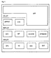
- Figure 1 shows a typical structure of a system architecture with the four layers of hardware HW-LAY, driver BSP-LAY, Operating system OS-LAY and application APP.
- This structure allows the processes to be separated from the Hardware. It can be seen that applications with APP time-critical functions directly, without detours via the Operate the OS-LAY operating system.
- the multi-computer communication units 2/3-COM and Synchronization & backup SYN & CHK in the driver layer classified. That means that the APP application is already from the Architecture is separated from the SYN & CHK synchronization.
- the synchronization unit SYN & CHK and the communication unit 2/3-COM is preferably used as an autonomous Driver function trained so that these units Being able to work independently and by everyone Applications APP and OS-LAY operating system can be used are.
- the driver units work together with the hardware and are therefore adapted to the computer. Not all of them Driver functions of the hardware must be adapted also driver functions use other driver functions, so that for many driver functions again generally applicable Approaches can be found.
- Synchronization takes place in two stages. On the one hand OS-LAY operating systems are synchronized, on the other hand data (application data) is synchronized.
- Figure 2 shows the structure of a time synchronization according to the invention of the system. With this time synchronization that time for the computer to become an external Dimension becomes. The time units begin and end all computers almost simultaneously. A synchronization under the computers can be done via serial connections.
- One of the computers designated R1 in FIG. 2, is called a kind of master, he has an active one Hardware timer HW.
- the process is not a master-slave process.
- the calculator R1 only serves to define the Order among the computers to complete the procedure simplify and clarify boundary conditions. At Error detection is absolutely equivalent to computers Boundary conditions more difficult to understand.
- the master computer can change, for example, if the original master was switched off.
- Time synchronization is started on computer R1 by an active hardware timer HW.
- a clock pulse of this hardware timer HW is called a tick.
- a telegram 1.1 resp. 2.1 Every time the tick occurs, the synchronization SYN-R1 of the computer R1 sends a telegram.
- the synchronization SYN-R2 is started on the computer R2 when this telegram from the computer R1 arrives. If a correct telegram 1.1 was received, a separate telegram 2.1 is sent back.
- the time synchronization SYN2 is triggered for the own operating system OS-R2. Actions can be triggered due to the time synchronization SYN2, for example starting an APP-R2 application or data synchronization or other inputs and outputs.
- the computer R1 triggers its time synchronization SYN1 of its operating system OS-R1 when it has received a correct telegram 2.2 from the computer R2.
- the computer R1 starts its application APP-R1.
- the computer R1 sends the first telegram 1.1 until it receives a telegram 2.1 from the computer R2.
- the same procedure is used for transmission interference. If a telegram from computer R1 cannot be received correctly on computer R2, computer R2 does not send a telegram back and computer R1 repeats the same telegram on the next tick.
- the number of repetitions until termination is adjustable. In the event of transmission interference from computer R2 to computer R1, the procedure can be exactly the same.
- a Hardware timer HW of each computer R1, R2 with the Occurrence of the tick are compared. By comparison, With defined time grids, the tick can fail can be clearly detected.
- the simultaneous failure of the Hardware timers on all computers can be controlled by a Time monitoring function (watchdog function) checked become.
- FIG. 3 shows a data synchronization of asynchronous Processes on computers R1 and R2.
- the data synchronization uses telegrams of a time synchronization for a data comparison between the computers R1 and R2. If no data synchronization is required, the telegrams advantageously only have information for time synchronization.
- an application transfers APP-R1 data D1 to a driver module of a synchronization SYN-R1.
- This driver module now requires a tick from a hardware timer HW to start the data synchronization.
- the APP-R1 application now waits until it receives valid data D1 from the computer R2 or until an application-specific exception procedure is started by a standstill check (timeout). Such a state of waiting can be communicated to the operating system OS-R1 with a message WS.
- timeout standstill check
- the data D1 are transmitted with the telegram 1.2 (D1) to the driver module of the synchronization SYN-R2 of the computer R2.
- the computer R2 replies with the telegram 2.2 without data D1, since this is not yet available from the APP-R2 application.
- the data synchronization of the computer R1 can therefore not yet synchronize the APP-R1 application.
- the complete data D1 is provided on the computer R2 by the computer R1 for the application APP-R1.
- the APP-R1 application has transferred its data D1 to the driver module SYN-R2, it now receives the data D1 from the computer R1 for checking.
- the APP-R2 application can thus continue its processing without delay.
- the data from the APP-R2 application is transferred with the next tick.
- response telegram 2.3 (D1) the computer R1 now receives the data from the computer R2, which are forwarded from the synchronization synchronization driver module to the APP-R1 application. After checking the data D1,
- FIG. 4 illustrates the division of the applications into subsystem steps in order to be able to ensure continuous data synchronization.
- Each application, sub-application, process or task can be divided into the basic units “read data” RD, “send data” TR, “receive data” RD, “check data” CP, "process data” PC1 and PC2 .
- read data RD
- send data TR
- receive data RD
- check data CP
- process data PC1 and PC2
- These locations are called synchronization points and can be assigned a synchronization number SYNNR according to FIG. 5 for identification.
- a system according to FIG. 4 supports both unitary and diverse processing of data. If checking the data CP detects an error, error handling EX can be started immediately. The error handling EX is application-specific and can, for example, cause the computer to stop with an external error message. If no errors were detected in such a subsystem step, the data are passed on to the next subsystem step OT for reading.
Landscapes
- Engineering & Computer Science (AREA)
- Theoretical Computer Science (AREA)
- Quality & Reliability (AREA)
- Physics & Mathematics (AREA)
- General Engineering & Computer Science (AREA)
- General Physics & Mathematics (AREA)
- Hardware Redundancy (AREA)
- Multi Processors (AREA)
- Synchronisation In Digital Transmission Systems (AREA)
- Communication Control (AREA)
Priority Applications (8)
| Application Number | Priority Date | Filing Date | Title |
|---|---|---|---|
| EP00112203A EP1162540A1 (fr) | 2000-06-07 | 2000-06-07 | Dispositif et procédure de synchronisation d'un système des unités couplées de traitement des données |
| AT01936422T ATE276545T1 (de) | 2000-06-07 | 2001-06-01 | Vorrichtung und verfahren zur synchronisation eines systems von gekoppelten datenverarbeitungsanlagen |
| PCT/EP2001/006240 WO2001097033A1 (fr) | 2000-06-07 | 2001-06-01 | Dispositif et procede pour la synchronisation d'un systeme d'installations informatiques couplees |
| JP2002511171A JP2004503868A (ja) | 2000-06-07 | 2001-06-01 | 接続された複数のデータ処理設備のシステムを同期調整するための装置及び方法 |
| EP01936422A EP1287435B1 (fr) | 2000-06-07 | 2001-06-01 | Dispositif et procede pour la synchronisation d'un systeme d'installations informatiques couplees |
| CA002411788A CA2411788C (fr) | 2000-06-07 | 2001-06-01 | Dispositif et procede pour la synchronisation d'un systeme d'installations informatiques couplees |
| DE50103642T DE50103642D1 (de) | 2000-06-07 | 2001-06-01 | Vorrichtung und verfahren zur synchronisation eines systems von gekoppelten datenverarbeitungsanlagen |
| US10/307,453 US20030158972A1 (en) | 2000-06-07 | 2002-12-02 | Device and method for the synchronization of a system of networked computers |
Applications Claiming Priority (1)
| Application Number | Priority Date | Filing Date | Title |
|---|---|---|---|
| EP00112203A EP1162540A1 (fr) | 2000-06-07 | 2000-06-07 | Dispositif et procédure de synchronisation d'un système des unités couplées de traitement des données |
Publications (1)
| Publication Number | Publication Date |
|---|---|
| EP1162540A1 true EP1162540A1 (fr) | 2001-12-12 |
Family
ID=8168934
Family Applications (2)
| Application Number | Title | Priority Date | Filing Date |
|---|---|---|---|
| EP00112203A Withdrawn EP1162540A1 (fr) | 2000-06-07 | 2000-06-07 | Dispositif et procédure de synchronisation d'un système des unités couplées de traitement des données |
| EP01936422A Expired - Lifetime EP1287435B1 (fr) | 2000-06-07 | 2001-06-01 | Dispositif et procede pour la synchronisation d'un systeme d'installations informatiques couplees |
Family Applications After (1)
| Application Number | Title | Priority Date | Filing Date |
|---|---|---|---|
| EP01936422A Expired - Lifetime EP1287435B1 (fr) | 2000-06-07 | 2001-06-01 | Dispositif et procede pour la synchronisation d'un systeme d'installations informatiques couplees |
Country Status (7)
| Country | Link |
|---|---|
| US (1) | US20030158972A1 (fr) |
| EP (2) | EP1162540A1 (fr) |
| JP (1) | JP2004503868A (fr) |
| AT (1) | ATE276545T1 (fr) |
| CA (1) | CA2411788C (fr) |
| DE (1) | DE50103642D1 (fr) |
| WO (1) | WO2001097033A1 (fr) |
Cited By (2)
| Publication number | Priority date | Publication date | Assignee | Title |
|---|---|---|---|---|
| CN108259227A (zh) * | 2017-12-22 | 2018-07-06 | 合肥工大高科信息科技股份有限公司 | 一种双机热备联锁系统的数据同步方法 |
| CN114407975A (zh) * | 2021-12-21 | 2022-04-29 | 合肥工大高科信息科技股份有限公司 | 一种全电子联锁系统执行单元的热备方法及热备联锁系统 |
Families Citing this family (2)
| Publication number | Priority date | Publication date | Assignee | Title |
|---|---|---|---|---|
| US8193481B2 (en) * | 2009-01-26 | 2012-06-05 | Centre De Recherche Industrielle De Quebec | Method and apparatus for assembling sensor output data with data representing a sensed location on a moving article |
| WO2020236164A1 (fr) | 2019-05-22 | 2020-11-26 | Vit Tall Llc | Synchronisation multi-horloge dans des réseaux électriques |
Citations (4)
| Publication number | Priority date | Publication date | Assignee | Title |
|---|---|---|---|---|
| US4937741A (en) * | 1988-04-28 | 1990-06-26 | The Charles Stark Draper Laboratory, Inc. | Synchronization of fault-tolerant parallel processing systems |
| US5551034A (en) * | 1993-01-08 | 1996-08-27 | Cegelec | System for synchronizing replicated tasks |
| US5751955A (en) * | 1992-12-17 | 1998-05-12 | Tandem Computers Incorporated | Method of synchronizing a pair of central processor units for duplex, lock-step operation by copying data into a corresponding locations of another memory |
| WO1999026133A2 (fr) * | 1997-11-14 | 1999-05-27 | Marathon Technologies Corporation | Systeme informatique presentant une resilience et une tolerance face aux defaillances |
Family Cites Families (4)
| Publication number | Priority date | Publication date | Assignee | Title |
|---|---|---|---|---|
| US5887143A (en) * | 1995-10-26 | 1999-03-23 | Hitachi, Ltd. | Apparatus and method for synchronizing execution of programs in a distributed real-time computing system |
| US6748451B2 (en) * | 1998-05-26 | 2004-06-08 | Dow Global Technologies Inc. | Distributed computing environment using real-time scheduling logic and time deterministic architecture |
| US6324586B1 (en) * | 1998-09-17 | 2001-11-27 | Jennifer Wallace | System for synchronizing multiple computers with a common timing reference |
| US7194556B2 (en) * | 2001-03-30 | 2007-03-20 | Intel Corporation | Method and apparatus for high accuracy distributed time synchronization using processor tick counters |
-
2000
- 2000-06-07 EP EP00112203A patent/EP1162540A1/fr not_active Withdrawn
-
2001
- 2001-06-01 WO PCT/EP2001/006240 patent/WO2001097033A1/fr active IP Right Grant
- 2001-06-01 EP EP01936422A patent/EP1287435B1/fr not_active Expired - Lifetime
- 2001-06-01 CA CA002411788A patent/CA2411788C/fr not_active Expired - Fee Related
- 2001-06-01 JP JP2002511171A patent/JP2004503868A/ja active Pending
- 2001-06-01 AT AT01936422T patent/ATE276545T1/de not_active IP Right Cessation
- 2001-06-01 DE DE50103642T patent/DE50103642D1/de not_active Expired - Lifetime
-
2002
- 2002-12-02 US US10/307,453 patent/US20030158972A1/en not_active Abandoned
Patent Citations (4)
| Publication number | Priority date | Publication date | Assignee | Title |
|---|---|---|---|---|
| US4937741A (en) * | 1988-04-28 | 1990-06-26 | The Charles Stark Draper Laboratory, Inc. | Synchronization of fault-tolerant parallel processing systems |
| US5751955A (en) * | 1992-12-17 | 1998-05-12 | Tandem Computers Incorporated | Method of synchronizing a pair of central processor units for duplex, lock-step operation by copying data into a corresponding locations of another memory |
| US5551034A (en) * | 1993-01-08 | 1996-08-27 | Cegelec | System for synchronizing replicated tasks |
| WO1999026133A2 (fr) * | 1997-11-14 | 1999-05-27 | Marathon Technologies Corporation | Systeme informatique presentant une resilience et une tolerance face aux defaillances |
Cited By (4)
| Publication number | Priority date | Publication date | Assignee | Title |
|---|---|---|---|---|
| CN108259227A (zh) * | 2017-12-22 | 2018-07-06 | 合肥工大高科信息科技股份有限公司 | 一种双机热备联锁系统的数据同步方法 |
| CN108259227B (zh) * | 2017-12-22 | 2021-01-08 | 合肥工大高科信息科技股份有限公司 | 一种双机热备联锁系统的数据同步方法 |
| CN114407975A (zh) * | 2021-12-21 | 2022-04-29 | 合肥工大高科信息科技股份有限公司 | 一种全电子联锁系统执行单元的热备方法及热备联锁系统 |
| CN114407975B (zh) * | 2021-12-21 | 2024-04-19 | 合肥工大高科信息科技股份有限公司 | 一种全电子联锁系统执行单元的热备方法及热备联锁系统 |
Also Published As
| Publication number | Publication date |
|---|---|
| JP2004503868A (ja) | 2004-02-05 |
| CA2411788C (fr) | 2006-07-25 |
| WO2001097033A1 (fr) | 2001-12-20 |
| CA2411788A1 (fr) | 2002-12-05 |
| ATE276545T1 (de) | 2004-10-15 |
| EP1287435B1 (fr) | 2004-09-15 |
| DE50103642D1 (de) | 2004-10-21 |
| US20030158972A1 (en) | 2003-08-21 |
| EP1287435A1 (fr) | 2003-03-05 |
Similar Documents
| Publication | Publication Date | Title |
|---|---|---|
| EP2657797B1 (fr) | Procédé de fonctionnement d'un système d'automatisation redondant | |
| DE19927635B4 (de) | Sicherheitsbezogenes Automatisierungsbussystem | |
| EP0972389B1 (fr) | Systeme de commande de securite et procede pour la mise en oeuvre d'un tel systeme | |
| DE10030329C1 (de) | Redundantes Steuerungssystem sowie Steuerrechner und Peripherieeinheit für ein derartiges Steuerungssystem | |
| EP2857913B1 (fr) | Système d'automatisation redondant | |
| DE102005055428B4 (de) | Busmodul zum Anschluss an ein Bussystem sowie Verwendung eines solchen Busmoduls in einem AS-i-Bussystem | |
| DE19744071B4 (de) | Eine programmierbare Logiksteuervorrichtung verwendendes Steuerungssystem | |
| DE102005061392A1 (de) | Bus-Guardian eines Teilnehmers eines Kommunikationssystems, sowie Teilnehmer für ein Kommunikationssystem | |
| EP1743225A1 (fr) | Systeme d'automatisation redondant comprenant un automate programmable maitre et un automate programmable reserve | |
| EP0543821B1 (fr) | Installation pour le controle des fonctions de modules de synchronisation externes dans un systeme a plusieurs ordinateurs | |
| DE102017109886A1 (de) | Steuerungssystem zum Steuern von sicherheitskritischen und nichtsicherheitskritischen Prozessen mit Master-Slave-Funktionalität | |
| EP1238318A1 (fr) | Automate programmable et procede d'actualisation | |
| DE19842593C2 (de) | Verfahren zum Betrieb eines Busmasters an einem Feldbus | |
| WO2004034260A2 (fr) | Procede et ensemble circuit de synchronisation d'unites de traitement cadencees de maniere synchrone ou asynchrone | |
| EP1287435B1 (fr) | Dispositif et procede pour la synchronisation d'un systeme d'installations informatiques couplees | |
| EP0246218B1 (fr) | Système de traitement de données à tolérance de fautes | |
| WO1998000782A1 (fr) | Dispositif pour faire fonctionner deux processeurs montes fonctionnellement en parallele | |
| EP0935198B1 (fr) | Méthode et système informatique de traitement de données sécurisée | |
| EP1426862B1 (fr) | Synchronisation de traitement de données dans des unités de traitement redondantes d'un système de traitement de données | |
| EP1277094B1 (fr) | Procede de surveillance pour installations de traitement de donnees en reseau | |
| EP2806316A1 (fr) | Procédé destiné au fonctionnement d'un système d'automatisation | |
| EP0299375B1 (fr) | Méthode pour connecter un calculateur dans un système multicalculateur | |
| EP0156388A2 (fr) | Agencement de traitement de données à sécurité de signal techniquement assurée | |
| DE3918962C2 (de) | System mit mehreren asynchron arbeitenden Rechnern | |
| EP2133764B1 (fr) | Système d'automatisation à sécurité intrinsèque et procédé |
Legal Events
| Date | Code | Title | Description |
|---|---|---|---|
| PUAI | Public reference made under article 153(3) epc to a published international application that has entered the european phase |
Free format text: ORIGINAL CODE: 0009012 |
|
| AK | Designated contracting states |
Kind code of ref document: A1 Designated state(s): AT BE CH CY DE DK ES FI FR GB GR IE IT LI LU MC NL PT SE |
|
| AX | Request for extension of the european patent |
Free format text: AL;LT;LV;MK;RO;SI |
|
| AKX | Designation fees paid | ||
| REG | Reference to a national code |
Ref country code: DE Ref legal event code: 8566 |
|
| STAA | Information on the status of an ep patent application or granted ep patent |
Free format text: STATUS: THE APPLICATION IS DEEMED TO BE WITHDRAWN |
|
| 18D | Application deemed to be withdrawn |
Effective date: 20020613 |