EP1162515A2 - Developing apparatus, process cartridge, connecting method between developing frame and developer frame, and flexible seal - Google Patents
Developing apparatus, process cartridge, connecting method between developing frame and developer frame, and flexible seal Download PDFInfo
- Publication number
- EP1162515A2 EP1162515A2 EP01114021A EP01114021A EP1162515A2 EP 1162515 A2 EP1162515 A2 EP 1162515A2 EP 01114021 A EP01114021 A EP 01114021A EP 01114021 A EP01114021 A EP 01114021A EP 1162515 A2 EP1162515 A2 EP 1162515A2
- Authority
- EP
- European Patent Office
- Prior art keywords
- developer
- developing
- opening
- process cartridge
- frame
- Prior art date
- Legal status (The legal status is an assumption and is not a legal conclusion. Google has not performed a legal analysis and makes no representation as to the accuracy of the status listed.)
- Granted
Links
- 238000000034 method Methods 0.000 title claims abstract description 367
- 230000008569 process Effects 0.000 title claims abstract description 316
- 238000007789 sealing Methods 0.000 claims description 92
- 238000004140 cleaning Methods 0.000 claims description 77
- 230000002093 peripheral effect Effects 0.000 claims description 39
- 239000000463 material Substances 0.000 claims description 38
- 239000010410 layer Substances 0.000 claims description 27
- 229920005989 resin Polymers 0.000 claims description 19
- 239000011347 resin Substances 0.000 claims description 19
- 238000003466 welding Methods 0.000 claims description 18
- JOYRKODLDBILNP-UHFFFAOYSA-N Ethyl urethane Chemical compound CCOC(N)=O JOYRKODLDBILNP-UHFFFAOYSA-N 0.000 claims description 8
- 150000002148 esters Chemical class 0.000 claims description 8
- 239000013013 elastic material Substances 0.000 claims description 7
- 239000005038 ethylene vinyl acetate Substances 0.000 claims description 7
- 239000004645 polyester resin Substances 0.000 claims description 7
- 229920001225 polyester resin Polymers 0.000 claims description 7
- 229920005672 polyolefin resin Polymers 0.000 claims description 7
- 229920005749 polyurethane resin Polymers 0.000 claims description 7
- 230000008859 change Effects 0.000 claims description 6
- 239000006260 foam Substances 0.000 claims description 6
- 239000002356 single layer Substances 0.000 claims description 6
- 238000011161 development Methods 0.000 description 182
- 230000008878 coupling Effects 0.000 description 90
- 238000010168 coupling process Methods 0.000 description 90
- 238000005859 coupling reaction Methods 0.000 description 90
- 238000003780 insertion Methods 0.000 description 29
- 230000037431 insertion Effects 0.000 description 29
- 239000003570 air Substances 0.000 description 28
- 238000003756 stirring Methods 0.000 description 26
- 125000006850 spacer group Chemical group 0.000 description 18
- 238000003825 pressing Methods 0.000 description 10
- 230000015572 biosynthetic process Effects 0.000 description 9
- 238000004873 anchoring Methods 0.000 description 8
- 238000001816 cooling Methods 0.000 description 8
- 229920006311 Urethane elastomer Polymers 0.000 description 7
- 230000006870 function Effects 0.000 description 7
- 239000000853 adhesive Substances 0.000 description 6
- 230000001070 adhesive effect Effects 0.000 description 6
- 239000002390 adhesive tape Substances 0.000 description 6
- 229920001971 elastomer Polymers 0.000 description 6
- 230000002829 reductive effect Effects 0.000 description 6
- 230000006835 compression Effects 0.000 description 5
- 238000007906 compression Methods 0.000 description 5
- 238000010586 diagram Methods 0.000 description 5
- 230000001105 regulatory effect Effects 0.000 description 5
- 239000000126 substance Substances 0.000 description 5
- OKTJSMMVPCPJKN-UHFFFAOYSA-N Carbon Chemical compound [C] OKTJSMMVPCPJKN-UHFFFAOYSA-N 0.000 description 4
- XAGFODPZIPBFFR-UHFFFAOYSA-N aluminium Chemical compound [Al] XAGFODPZIPBFFR-UHFFFAOYSA-N 0.000 description 4
- 229910052782 aluminium Inorganic materials 0.000 description 4
- 229910052799 carbon Inorganic materials 0.000 description 4
- 239000007769 metal material Substances 0.000 description 4
- 229910001220 stainless steel Inorganic materials 0.000 description 4
- 239000010935 stainless steel Substances 0.000 description 4
- 238000012546 transfer Methods 0.000 description 4
- 230000001276 controlling effect Effects 0.000 description 3
- 238000005304 joining Methods 0.000 description 3
- 238000012545 processing Methods 0.000 description 3
- 239000004734 Polyphenylene sulfide Substances 0.000 description 2
- 230000009471 action Effects 0.000 description 2
- 239000012080 ambient air Substances 0.000 description 2
- 230000001186 cumulative effect Effects 0.000 description 2
- 230000007423 decrease Effects 0.000 description 2
- 238000010438 heat treatment Methods 0.000 description 2
- 229920005669 high impact polystyrene Polymers 0.000 description 2
- 239000004797 high-impact polystyrene Substances 0.000 description 2
- 238000004519 manufacturing process Methods 0.000 description 2
- 230000007246 mechanism Effects 0.000 description 2
- 229920000069 polyphenylene sulfide Polymers 0.000 description 2
- 229920001296 polysiloxane Polymers 0.000 description 2
- 230000004044 response Effects 0.000 description 2
- 239000000725 suspension Substances 0.000 description 2
- 229920003002 synthetic resin Polymers 0.000 description 2
- 239000000057 synthetic resin Substances 0.000 description 2
- 229910000906 Bronze Inorganic materials 0.000 description 1
- 206010013975 Dyspnoeas Diseases 0.000 description 1
- VGGSQFUCUMXWEO-UHFFFAOYSA-N Ethene Chemical compound C=C VGGSQFUCUMXWEO-UHFFFAOYSA-N 0.000 description 1
- 239000005977 Ethylene Substances 0.000 description 1
- 101000793686 Homo sapiens Azurocidin Proteins 0.000 description 1
- 239000004677 Nylon Substances 0.000 description 1
- OAICVXFJPJFONN-UHFFFAOYSA-N Phosphorus Chemical compound [P] OAICVXFJPJFONN-UHFFFAOYSA-N 0.000 description 1
- 229930182556 Polyacetal Natural products 0.000 description 1
- 239000004952 Polyamide Substances 0.000 description 1
- 239000004743 Polypropylene Substances 0.000 description 1
- 241000519995 Stachys sylvatica Species 0.000 description 1
- XTXRWKRVRITETP-UHFFFAOYSA-N Vinyl acetate Chemical compound CC(=O)OC=C XTXRWKRVRITETP-UHFFFAOYSA-N 0.000 description 1
- 230000002411 adverse Effects 0.000 description 1
- 230000008901 benefit Effects 0.000 description 1
- 238000007664 blowing Methods 0.000 description 1
- 239000010974 bronze Substances 0.000 description 1
- DQXBYHZEEUGOBF-UHFFFAOYSA-N but-3-enoic acid;ethene Chemical compound C=C.OC(=O)CC=C DQXBYHZEEUGOBF-UHFFFAOYSA-N 0.000 description 1
- 229920001577 copolymer Polymers 0.000 description 1
- KUNSUQLRTQLHQQ-UHFFFAOYSA-N copper tin Chemical compound [Cu].[Sn] KUNSUQLRTQLHQQ-UHFFFAOYSA-N 0.000 description 1
- 238000005520 cutting process Methods 0.000 description 1
- 230000007547 defect Effects 0.000 description 1
- 239000003989 dielectric material Substances 0.000 description 1
- 238000006073 displacement reaction Methods 0.000 description 1
- 238000005516 engineering process Methods 0.000 description 1
- 238000007667 floating Methods 0.000 description 1
- 230000005484 gravity Effects 0.000 description 1
- 239000012943 hotmelt Substances 0.000 description 1
- 230000006872 improvement Effects 0.000 description 1
- 230000010354 integration Effects 0.000 description 1
- 238000012423 maintenance Methods 0.000 description 1
- 238000002844 melting Methods 0.000 description 1
- 230000008018 melting Effects 0.000 description 1
- 238000012986 modification Methods 0.000 description 1
- 230000004048 modification Effects 0.000 description 1
- 229920001778 nylon Polymers 0.000 description 1
- 230000036961 partial effect Effects 0.000 description 1
- 229920001200 poly(ethylene-vinyl acetate) Polymers 0.000 description 1
- 229920002647 polyamide Polymers 0.000 description 1
- 229920000139 polyethylene terephthalate Polymers 0.000 description 1
- 239000005020 polyethylene terephthalate Substances 0.000 description 1
- 229920006324 polyoxymethylene Polymers 0.000 description 1
- -1 polypropylene Polymers 0.000 description 1
- 229920001155 polypropylene Polymers 0.000 description 1
- 230000009467 reduction Effects 0.000 description 1
- 239000012260 resinous material Substances 0.000 description 1
- 230000000284 resting effect Effects 0.000 description 1
- 230000000717 retained effect Effects 0.000 description 1
- 230000002441 reversible effect Effects 0.000 description 1
- 229920002379 silicone rubber Polymers 0.000 description 1
- 238000005549 size reduction Methods 0.000 description 1
- 230000037303 wrinkles Effects 0.000 description 1
Images











Classifications
-
- G—PHYSICS
- G03—PHOTOGRAPHY; CINEMATOGRAPHY; ANALOGOUS TECHNIQUES USING WAVES OTHER THAN OPTICAL WAVES; ELECTROGRAPHY; HOLOGRAPHY
- G03G—ELECTROGRAPHY; ELECTROPHOTOGRAPHY; MAGNETOGRAPHY
- G03G15/00—Apparatus for electrographic processes using a charge pattern
- G03G15/06—Apparatus for electrographic processes using a charge pattern for developing
-
- G—PHYSICS
- G03—PHOTOGRAPHY; CINEMATOGRAPHY; ANALOGOUS TECHNIQUES USING WAVES OTHER THAN OPTICAL WAVES; ELECTROGRAPHY; HOLOGRAPHY
- G03G—ELECTROGRAPHY; ELECTROPHOTOGRAPHY; MAGNETOGRAPHY
- G03G21/00—Arrangements not provided for by groups G03G13/00 - G03G19/00, e.g. cleaning, elimination of residual charge
- G03G21/16—Mechanical means for facilitating the maintenance of the apparatus, e.g. modular arrangements
- G03G21/18—Mechanical means for facilitating the maintenance of the apparatus, e.g. modular arrangements using a processing cartridge, whereby the process cartridge comprises at least two image processing means in a single unit
- G03G21/1803—Arrangements or disposition of the complete process cartridge or parts thereof
- G03G21/1828—Prevention of damage or soiling, e.g. mechanical abrasion
- G03G21/1832—Shielding members, shutter, e.g. light, heat shielding, prevention of toner scattering
-
- G—PHYSICS
- G03—PHOTOGRAPHY; CINEMATOGRAPHY; ANALOGOUS TECHNIQUES USING WAVES OTHER THAN OPTICAL WAVES; ELECTROGRAPHY; HOLOGRAPHY
- G03G—ELECTROGRAPHY; ELECTROPHOTOGRAPHY; MAGNETOGRAPHY
- G03G15/00—Apparatus for electrographic processes using a charge pattern
- G03G15/06—Apparatus for electrographic processes using a charge pattern for developing
- G03G15/08—Apparatus for electrographic processes using a charge pattern for developing using a solid developer, e.g. powder developer
- G03G15/0896—Arrangements or disposition of the complete developer unit or parts thereof not provided for by groups G03G15/08 - G03G15/0894
- G03G15/0898—Arrangements or disposition of the complete developer unit or parts thereof not provided for by groups G03G15/08 - G03G15/0894 for preventing toner scattering during operation, e.g. seals
-
- G—PHYSICS
- G03—PHOTOGRAPHY; CINEMATOGRAPHY; ANALOGOUS TECHNIQUES USING WAVES OTHER THAN OPTICAL WAVES; ELECTROGRAPHY; HOLOGRAPHY
- G03G—ELECTROGRAPHY; ELECTROPHOTOGRAPHY; MAGNETOGRAPHY
- G03G2221/00—Processes not provided for by group G03G2215/00, e.g. cleaning or residual charge elimination
- G03G2221/16—Mechanical means for facilitating the maintenance of the apparatus, e.g. modular arrangements and complete machine concepts
- G03G2221/18—Cartridge systems
- G03G2221/183—Process cartridge
Definitions
- the present invention relates to a process cartridge removably mountable in an electrophotographic image forming apparatus, a method for joining a developing means holding frame and a developer holding frame, and a flexible sealing member.
- an electrophotographic image forming apparatus means an apparatus which forms an image on recording medium with the use of an electrophotographic image formation method.
- an electrophotographic image forming apparatus there are an electrophotographic copying machine, an electrophotographic printer (for example, a laser printer, an LED printer, and the like), a facsimile machine, a word processor, and the like.
- a process cartridge means a cartridge which integrally comprises a charging means, a developing means or a cleaning means, and an electrophotographic photosensitive drum, and is removably mountable in the main assembly of an image forming apparatus. It also means a cartridge which integrally comprises a minimum of one means among a charging means, a developing means, and cleaning means, and an electrophotographic photosensitive drum, and is removably mountable in the main assembly of an image forming apparatus, and a cartridge which integrally comprises a minimum of a developing means, and an electrophotographic photosensitive drum, and is removably mountable in the main assembly of an image forming apparatus.
- a process cartridge system is employed by an electrophotographic image forming apparatus which employs an electrophotographic image formation process.
- an electrophotographic photosensitive member, and a single or a plurality of processing means, which act on the electrophotographic photosensitive member are integrated in the form of a cartridge removably mountable in the main assembly of an image forming apparatus.
- a process cartridge system makes it possible for a user to maintain an electrophotographic image forming apparatus without relaying on service personnel, remarkably improving an electrophotographic image forming apparatus in operational efficiency. Therefore, a process cartridge system is widely used in the field of an image forming apparatus.
- a conventional process cartridge 85 comprises a development unit and a cleaning unit, which are joined with each other with the use of connecting pins 89.
- the development unit comprises a developing means container 83 and a toner container 86, which are welded to each other by ultrasonic welding.
- the developing means container 83 supports developing members such as a development roller.
- the cleaning unit comprises a photosensitive drum 11, a charge roller 12, a cleaning blade 14, a cleaning means container 87, and the like.
- the photosensitive drum 11, charge roller 12, cleaning blade 14, and the like, are supported by the cleaning means container 87.
- a pair of compression springs 82 are placed in a compressed state between the cleaning means container 87 and developing means container 83, keeping the photosensitive drum 11 and development roller 18 pressed toward each other.
- the developing means container 83 and toner container 86 are solidly joined to each other with the use of ultrasonic welding, thermal welding, adhesive, or the like.
- the solidly joined combination of the developing means container 83 and toner container 86 is connected to the cleaning means container 87, which doubles as a removed toner container, in such a manner that the combination can move relative to the cleaning means container 87, in other words, can pivot about the connecting pin 89.
- toner container As a toner container is increased in capacity with the use of any of the conventional technologies, the amount of developer (toner) filled in the toner container increases, which results in the increase in the amount of the load which applies to the spacer rings and also in the amount of the load which applies to the development roller 18 and photosensitive drum 11.
- the primary object of the present invention is to provide a method for connecting a developing means frame and developer holding frame in such a manner that the two frames are movable relative to each other; a developing apparatus, which comprises a developing means frame and a developer holding frame, which are movable relative to each other; a process cartridge; and a flexible sealing member suitable for using said connecting method.
- Another object of the present invention is to provide a method for connecting a developing means frame and a developer holding frame in such a manner that the load which applies to a developing member and an electrophotographic photosensitive member does not fluctuate in response to the amount of the developer; a developing apparatus and a process cartridge, in which the load which applies to a developing member and an electrophotographic photosensitive member does not fluctuate in response to the amount of the developer; and a flexible sealing member suitable for said connecting method.
- Another object of the present invention is to provide a method for connecting a developing means frame and a developer holding frame in such a manner that the load which applies to a developing member and an electrophotographic photosensitive member does not increase even if the amount of the developer stored in the developer holding frame increases; a developing apparatus and a process cartridge, in which a developing means holding frame and a developer holding frame are connected to each other in such a manner that the two frames are movable relative to each other; and a flexible sealing member suitable for said connecting method.
- Another object of the present invention is to provide: a method for connecting a developing means frame and a developer holding frame in such a manner that the load which applies to a developing member and an electrophotographic photosensitive member does not increase even when the developer container is increased in capacity, and also that the load which applies to a developing member and an electrophotographic photosensitive member does not change even when the amount of the developer within the developer container decreases; a developing apparatus and a process cartridge, which comprise a developing means frame and a developer holding frame, which are connected to each other with the use of said connecting method; and a flexible sealing member suitable for said connecting method.
- Another object of the present invention is to provide a developing apparatus and a process cartridge, in which a flexible seal is folded so that the first and second holes of the flexible sheet align with each other, and the two halves of the flexible sheet created by the folding are pasted to each other at their edges.
- the longitudinal direction means such a direction that is perpendicular to the direction in which recording medium is conveyed, and that is parallel to the surface of the recording medium.
- the top and bottom surfaces of a process cartridge means the top and bottom surfaces of the process cartridge which has been properly mounted in the main assembly of an image forming apparatus.
- FIG. 2 is a sectional view of a process cartridge in accordance with the present invention, at a plane perpendicular to the longitudinal direction
- Figure 1 is a sectional view of an image forming apparatus in accordance with the present invention, at a plane perpendicular to the longitudinal direction.
- This process cartridge comprises an electrophotographic photosensitive member, and a plurality of processing means which act on the electrophotographic photosensitive member.
- the processing means there are a charging means for charging the peripheral surface of the electrophotographic photosensitive member, a developing means for developing an electrostatic latent image formed on the electrophotographic photosensitive member, and a cleaning means for removing the developer remaining on the peripheral surface of the electrophotographic photosensitive member.
- a charging member 12 as a charging means, a development roller as a developing means, a development blade as a developing means, and a cleaning member 14 as a cleaning means are positioned around the electrophotographic photosensitive drum 11. These components are integrally covered with a housing, forming the process cartridge 15 which is removably mountable in the main assembly 27 of an image forming apparatus (which hereinafter will be referred to as an apparatus main assembly).
- the charging member 12 is a charge roller, which comprises a metallic core and a layer of rubber wrapped around the metallic core. The electrical resistance of the rubber layer is in the medium range.
- the cleaning member 14 comprises a rubber blade placed in contact with the peripheral surface of the photosensitive drum 11 to scrape away the toner remaining on the photosensitive drum 11 after image transfer, and a metallic plate to which the rubber blade is fixed.
- this process cartridge 15 is mounted in an electrophotographic image forming apparatus C to be used for image formation.
- a sheet S is conveyed by a conveying roller 7 from a sheet cassette 6 mounted in the bottom portion of the apparatus main assembly.
- a latent image is formed by selectively exposing the peripheral surface of the photosensitive drum 11 with the use of an exposing apparatus 8.
- the toner stored in a toner container 16 is coated in a thin layer on the peripheral surface of the development roller 18 by the development blade 26, while being triboelectrically charged.
- the toner on the development roller 18 is supplied to the peripheral surface of the photosensitive drum 11, in accordance with the latent image, by applying development bias to the development roller 18.
- a toner image is formed on the peripheral surface of the photosensitive drum 11.
- This toner image is transferred onto the sheet S as recording medium, which is being conveyed, by the application of bias voltage to the transfer roller 9.
- the sheet S is conveyed to a fixing apparatus 10, in which the toner image is fixed to the sheet S.
- the sheet S is discharged into a sheet delivery portion 2 at the top of the apparatus main assembly, by a discharge roller 1.
- the toner remaining on the photosensitive drum 11 is removed by the cleaning member 14, and is moved inward of a removed toner bin 5 by a removed toner moving member 115.
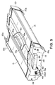
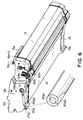
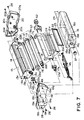
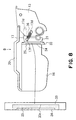
- Figures 3 - 9 are drawings for showing the structure of the process cartridge frame.
- Figure 7 is a drawing which shows the components of the process cartridge prior to their assembly.
- Figures 3 - 6 are drawings of the process cartridge after its assembly.
- the process cartridge 15 comprises three frames: a cleaning means holding frame 13, which integrally supports the photosensitive drum 11, charging member 12, and cleaning member 14; a developing means holding frame 17 (which may be referred to as a development frame) which integrally supports the development roller 18, and a development blade (which is not shown in Figure 7, and is shown in Figure 2, being designated by a referential code 26); and a developer holding frame 16 which constitutes a developer container 16h for holding developer (which hereinafter will be referred to as toner).
- a cleaning means holding frame 13 which integrally supports the photosensitive drum 11, charging member 12, and cleaning member 14
- a developing means holding frame 17 which integrally supports the development roller 18, and a development blade (which is not shown in Figure 7, and is shown in Figure 2, being designated by a referential code 26)
- the developer holding frame 16 is provided with a cover 45, which is attached to the bottom of the developer holding frame 16 and will be referred to as a bottom cover.
- the process cartridge 15 comprises a pair of end covers 19 and 20, which are fixed to the longitudinal ends, one for one, of both the cleaning means holding frame 13 and developer holding frame 16.
- the developing means holding frame 17 is supported by the cleaning means holding frame 13.
- the frame which supports the photosensitive drum 11 may be referred to as a drum frame.
- the process cartridge 15 has the bottom cover 45, which is attached to the process cartridge 15, at a location which will be below the development roller 18 as a developing member, and a development blade 26 as a developing member after the mounting of the process cartridge 15 in the apparatus main assembly 27. It constitutes a part of the external wall of the process cartridge 15.
- One end of the bottom cover 45 in terms of the longitudinal direction is connected to the end cover 19, or the end cover on the rear end of the process cartridge 15 in terms of the process cartridge insertion direction, and the other end of the bottom cover 45 is connected to the end cover 20, or the end cover on the front end of the process cartridge 15 in terms of the process cartridge insertion direction.
- the rear end cover 19 has a second handle 29, which is grasped by an operator when the process cartridge 15 is mounted into or dismounted from the apparatus main assembly 27 by the operator.
- the process cartridge 15 is mounted into or removed from the apparatus main assembly 27 in the direction parallel to the longitudinal direction of the photosensitive drum 11. More specifically, when the process cartridge 15 is mounted into the apparatus main assembly 27, it is inserted all the way into the apparatus main assembly 27 in the longitudinal direction, and then, is lowered into the apparatus main assembly 27, whereas when it is removed from the apparatus main assembly 27, it is first moved upward and then is pulled out in the longitudinal direction.
- the rear end cover 19 is provided with a hole 19a, through which a shaft 22a1, the axial line of which coincides with the that of the shaft which bears the photosensitive drum, extends outward.
- the shaft 22a1 is a part of a bearing member 22a with which one of the longitudinal ends of the photosensitive drum 11 is supported by the cleaning means holding frame 13. It is accurately positioned relative to the apparatus main assembly 27 as the process cartridge 15 is mounted into the apparatus main assembly 27. More specifically, first, the process cartridge 15 is inserted straight into the apparatus main assembly 27 as far as possible, and then, is lowered into the apparatus main assembly 27.
- the shaft portion (positioning member) 22a1 integral with the drum shaft engages into the positioning recess (which will be described later) of the apparatus main assembly 27. While the process cartridge 15 is inserted into, or pulled out of, the apparatus main assembly 27, the process cartridge 15 is supported by the apparatus main assembly 27 at the guide portions 19g and 20g.
- the developer holding frame 16 is provided with a first handle 30, which is on the top surface of the process cartridge 15.
- the top surface of the process cartridge 15 means a surface of the process cartridge 15, which faces upward after the mounting of the process cartridge 15 into the apparatus main assembly 27.
- the first handle 30 is a handle which is grasped by an operator when the process cartridge 15 is carried. It folds into the recess 16e in the top surface of the developer holding frame 16. It is attached to the developer holding frame 16 by its base portions 30a with the use of pins (unshown) parallel to the longitudinal direction. When the first handle 30 is used, it is rotated about the pins to the position at which it becomes upright relative to the top surface of the process cartridge 15.
- the cleaning means holding frame 13 is provided with an exposure opening 13, through which the light, which is projected from the exposing apparatus 8 of the apparatus main assembly 27 while being modulated with image formation information, is allowed to enter the process cartridge 15 to expose the photosensitive drum 11.
- the front end cover 20 is provided with a first hole 20a and a second hole 20e.
- a first coupling 105a is fitted, which is a first driving force receiving portion for receiving the driving force for rotating the photosensitive drum 11 from the apparatus main assembly 27 after the mounting of the process cartridge 15 into the apparatus main assembly 27.
- the first coupling 105a as a driving force receiving portion is an integrally formed part of a flange 11a shown in Figure 7.
- the flange 11a is fixed to one of the longitudinal ends of the photosensitive drum 11.
- a second coupling 106a as a second driving force receiving portion is fitted, which receives, from the apparatus main assembly 27, the driving force for rotating stirring members 113, 114, and 123 ( Figure 2) as toner moving members for sending out the toner stored in the developer container 16h of the developer holding frame 16 after the mounting of the process cartridge 15 into the apparatus main assembly 27.
- the end covers 19 and 20 are large enough to virtually perfectly cover the corresponding ends of the process cartridge 15 in the longitudinal direction (large enough to match in size and shape the cross section of the process cartridge 15 at a plane perpendicular to the longitudinal direction), and are located at the ends of the process cartridge 15 in the longitudinal direction, one for one.
- the end covers 19 and 20 each extend across the longitudinal ends of the cleaning means holding frame 13 and developer holding frame 16, and are fixed to the cleaning means holding frame 13 and developer holding frame 16, thereby holding the cleaning means holding frame 13 and 16 together.
- the positions of the end covers 19 and 20 are fixed relative to the cleaning means holding frame 13 and developer holding frame 16 so that the centers of the holes 19a and 20a shown in Figure 7 align with the axial line of the photosensitive drum 11 supported by the cleaning means holding frame 13.
- the bearing member 22a is pressed into the hole 13a of the cleaning means holding frame 13, and small screws 49 are put through the flange 22a2 and are screwed into the cleaning means holding frame 13.
- the bearing member 22a comprises the flange 22a2 and the shaft 22a1 integrally formed with the flange 22a2.
- the shaft 22a1 is put through the hole 13a, and then, the end of the shaft 22a1 is slid into the center hole of the flange 11b.
- the flange 11b is immovably fitted to one of the longitudinal ends of the photosensitive drum 11, the flange 11b is immovably fitted. Since the position of the rear end cover 19 relative to the cleaning means holding frame 13 is fixed by the outward shaft 22a1 of the bearing member 22a, the rear end cover 19 is accurately positioned relative to the photosensitive drum 11.
- the positioning portion 19b that is, one of the joggles of the rear end cover 19, which is positioned as far as possible from the photosensitive drum 11, is fitted in the positioning portion 13b, that is, one of the holes of the side wall 13c of the cleaning means holding frame 13. With this arrangement, the rear end cover 19 is prevented from rotating about the axial line of the photosensitive drum 11.
- the rear end cover 19 is fixed to the side wall 13c of the cleaning means holding frame 13, that is, one of the end walls of the cleaning means holding frame 13 in terms of the longitudinal direction.
- the developer holding frame 16 is provided with cylindrical positioning portions 16a and 16b, which are on the side wall 16d, that is, one of the end walls of the developer holding frame 16 in terms of the longitudinal direction.
- the positioning portions 16a and 16b project in the longitudinal direction. They are fitted in the positioning portions 19c and 19d, which are holes of the rear end cover 19. With this arrangement, the positions of the developer holding frame 16 and rear end cover 16 relative to each other are fixed.
- the developer holding frame 16 and rear end cover 16 are fixed to each other.
- the other end cover, or the front end cover 20 is accurately positioned relative to the developer holding frame 16 and 13, and is fixed to them, in the same manner as is the rear end cover 19.
- the shaft of the bearing member 22b fixed to the cleaning means holding frame 13 by being pressed into the cleaning means holding frame 13 is fitted in the hole 20a of the front end cover 20, in such a manner that a portion of the bearing member 22b extends outward from the front end cover 20.
- the bearing members 22 double as members for accurately positioning the process cartridge 15 relative to the apparatus main assembly 27; in other words, the bearing members 22 are cylindrical members for fixing the position of the process cartridge 15.
- the position of the developing means holding frame 17 relative to other components is fixed by a method which will be described later.
- the cartridge frame essentially comprises the cleaning means holding frame 13, developer holding frame 16, developing means holding frame 17, end cover 19, and end cover 20.
- the cartridge frame is temporarily assembled prior to its permanent assembly.
- the shaft 22a1 projecting from the cleaning means holding frame 13 is put through the hole 19a of the rear end cover 19;
- the positioning portion (cylindrical joggle) 19b of the rear end cover 19 is put through the positioning hole 13b of the side wall of the cleaning means holding frame 13;
- the positioning portions 16a and 16b of the end wall of the developer holding frame 16 are put through the positioning portions (holes) 19c and 19d of the rear end cover 19.
- the front end cover 20 side the front end cover 20, cleaning means holding frame 13, and developer holding frame 16 are joined with each other in the same manner as on the rear end cover 19 side. Since these components can be temporarily assembled as described, they are easy to handle or put together before they are permanently fixed to each other.
- first small screws 28 are put through the positioning portions 19c and 19d and screwed into the positioning portions 16a and 16b. Also, an additional small screw 28 is put through the hole 19h of the rear end cover 19 and screwed into the hole of the joggle 13e of the cleaning means holding frame 13.
- the positioning portions 19c and 19d, and hole 19h are step holes, the outward sides of which are smaller in diameter. The smaller diameter portions of the holes are large enough in diameter for the screws 28 to be put through, but are smaller in diameter than the positioning portions 16a and 16b, and the joggle 13e.
- the cleaning means holding frame 13 and developer holding frame 16 are held together by the front end cover 20 in the same manner as they are by the rear end cover 19.
- the cleaning means holding frame 13 and developer holding frame 16 may be held together by the end covers 19 and 20 with the use of resin.
- the end covers 19 and 20, cleaning means holding frame 13, and developer holding frame 16 are provided with resin flow paths, which must be formed along the joining edges of the end covers 19 and 20, cleaning means holding frame 13, and developer holding frame 16, when these components are formed.
- melted resin is poured into the resin flow paths from the gate of a fixing jig, which is different from the jig used for forming the end covers 19 and 20, through a resin pouring path set up between the gate and the resin flow paths.
- the poured melted resin is allowed to solidify in the resin flow paths to keep the cleaning means holding frame 13 and developer holding frame 16 together by the end covers 19 and 20.
- the process cartridge 15 is temporarily assembled in advance, and placed in the fixing jig used for joining the cleaning means holding frame 13 and developer holding frame 16 by the end covers 19 and 20 with the use of resin.
- the developer holding frame 16 and developing means holding frame 17 are provided with a developer supplying hole 16c ( Figure 2) and a developer receiving hole 17b, respectively, for supplying toner from the developer holding frame 16 to development roller 18.
- the developer holding frame 16 and developing means holding frame 17 are connected to each other, with the interposition of a flexible seal 21 ( Figure 7), in such a manner that the aforementioned holes 17b and 16c form a through hole between the two frames 16 and 17.
- the position of the developer holding frame 16 is fixed relative to the end covers 19 and 20, whereas the position of the developing means holding frame 17 is fixed relative to the cleaning means holding frame 13. Therefore, a certain amount of gap must be provided between the developing means holding frame 17 and developer holding frame 16 because it is possible that the two frames may have dimensional errors.
- the position of the process cartridge 15 relative to the apparatus main assembly 27 is fixed as the position of the cleaning means holding frame 13 relative to the cartridge mounting portion of the apparatus main assembly 27 is fixed as the process cartridge 15 is inserted into the apparatus main assembly 27.
- the process cartridge 15 is structured so that the joint between the developing apparatus D and developer holding frame 16 remains sealed. More specifically, the flexible seal 21 is folded in half, and the two halves of the flexible seal 21 are pasted to each other, forming a sealing member in the form of a bellow, and this bellows-like sealing member is pasted to the developing apparatus D and developer holding frame 16.
- the flexible seal 21 is attached to the developer holding frame 16 with the interposition of a backing plate 33 as a connecting member.
- the flexible seal 21 in this embodiment is no more than 1 mm in thickness. However, the thickness of the flexible seal 21 may be more than 1 mm as long as a material which does not reduce the flexibility of the flexible seal 21 when the flexible seal 21 is folded in the form of bellows is selected as the material for the flexible seal 21.
- the flexible seal 21 is provided with first and second hole 21e and 21f.
- the first hole 21e is the same or larger in size than the hole 33b of the backing plate 33.
- the second hole 21f is the same or larger in size than the developer receiving hole 17b of the developing means holding frame 17.
- the flexible seal 21 is adhered to the backing plate 33 and developing means holding frame 17 by first and second adhering portions 21k and 21m, respectively, that is, the surrounding edges (hatched portions in Figure 10) of the holes 22e and 22f, so that the holes 22e and 22f align with the hole 33 of the backing plate 33 and the toner receiving hole 17b of the developing means holding frame 17.
- first hole 21 e of the flexible seal 21 is connected to the developer receiving hole 17b of the developing means holding frame 17, forming a through hole
- the second hole 21f of the flexible seal 21 is connected to the hole 33b of the backing plate 33, forming a through hole, as shown in Figure 11.
- the developer holding frame 16, developing means holding frame 17, backing plate 33, and flexible seal 21 are thermally welded to each other by a heat seal method, an impulse seal method, or the like. However, they may be bonded by ultrasonic welding, adhesive, adhesive tape, or the like.
- the flexible seal 21 is folded in the direction indicated by an arrow mark so that the developer receiving hole 17b and the hole 33 of the backing plate 33b align with each other, with the interposition of the flexible seal 21 between the developing means holding frame 17 and backing plate 33.
- the flexible seal 21 is shaped like a bellows (or a pouch).
- the mutually facing halves of the flexible seal 21 are joined to each other by their edges 21d (hatched portions), sealing between the developing means holding frame 17 and backing plate 33.
- a thermal welding method such as a heat seal method or an impulse seal method, ultrasonic welding, adhesive, adhesive tape, or the like, may be used.
- the backing plate 33 is attached to the developer holding frame 16.
- a portion of the backing plate 33 is not welded or glued to the developer holding frame 16 so that a developer seal can be passed through between the developer holding frame 16 and backing plate 33.
- the backing plate 33 is welded by the portion 33a; the portion correspondent to the area across which the toner sealing member 2 25 presses upon the developer seal 24 is not welded.
- the portion 33a is one of the edges of the backing plate 33 in the longitudinal direction, that is, one of the edges which extend in the width direction, or the direction perpendicular to the longitudinal direction.
- the flexible seal 21 as a sealing member forms a pouch or a bellows by being folded and welded, the resistance to the change in the gap between the mutually facing surfaces of the developer holding frame 16 and developing means holding frame 17, which occurs as the gap changes, is extremely small. Further, the interposition of the flexible seal 21 between the backing plate 33 and developing means holding frame 17 makes it possible to attach the backing plate 33 in a manner to cover the developer seal 24, and also to attach the toner sealing member 25 to the backing plate 33 in a manner to keep sealed the gap through which the developer seal 24 is passed. As a result, toner leakage is prevented.
- the provision of the backing plate 33 makes it possible to simplify the shape of a welding table necessary for welding, compared to a structural arrangement in which a sealing member in the form of a sheet is directly pasted to the developer holding frame 16.
- the provision of the backing plate 33 makes it possible to unitize the flexible seal 21 with the developing means holding frame 17, thereby making it easier to attach the flexible seal 21 to the developer holding frame 16.
- the flexible seal 21 is no more than 0.1 mm in thickness. It is a single layer sheet, and is kept on a backing sheet until it is used. Using a single layer sheet as the material for the flexible seal 21 makes it possible to render the flexible seal 21 less rigid.
- the flexible seal 21 in this case comprises a flexible layer 21a and a backing sheet 21b which is more rigid than the layer 21a.
- the layer 21a is formed of polyethylene-terephthalate, polypropylene, biaxial orientation Nylon, heat seal member, ester resin, ethylene vinyl acetate, polyurethane resin, polyester resin, olefin resin, or the like.
- a jig 31 for holding the flexible seal 21 is provided with a plurality of holes 31a for holding the flexible seal 21 by suction. These holes 31 a are connected to an unshown vacuum pump.
- the flexible seal 21 is held to the holding jig 31, with the layer 21a facing the holes 31a, as shown in Figure 13.
- the flexible seal 21 may be electrostatically held to the holding jig 31 by charging the surface of the holding jig 31. With the flexible seal 21 held to the holding jig 31, the backing sheet 21b, or the second layer of the flexible seal 21, is peeled as shown in Figure 14, leaving only the layer 21a (actual seal 21) on the holding jig 31.
- the holding jig 31 is provided with a heat generating member 32 for impulse sealing.
- the layer 21a of the flexible seal 21 held by the holding jig 31 is pressed onto the backing plate 33 and developing means holding frame 17.
- electrical current is briefly flowed through the heat generating member 32 to generate heat, and then, the layer 21a of the flexible seal 21 is allowed to cool. As a result, the layer 21a of the flexible seal 21 becomes welded to the backing plate 33 and developing means holding frame 17.
- the vacuum pump is stopped, and the holding jig 31 is raised to be moved away from the layer 21a of the flexible seal 21 having become welded to the developing means holding frame 17 and backing plate 33.
- the backing plate 33 functions as a part of the developer holding frame 16. In other words, in reality, the hole 33b of the backing plate 33 becomes the hole of the developer holding frame 16.
- the flexible seal 21 (layer 21a) is adhered to the backing plate 33 and developing means holding frame 17 in such a manner that the surrounding edges of the holes 21e and 21f of the flexible seal 21 are adhered to the surrounding edge of the hole 33b of the backing plate 33, and the surrounding edge of the developer receiving hole 17b of the developing means holding frame 17, respectively.
- the flexible seal 21 (layer 21a) is welded to the developing means holding frame 17 and backing plate 33 as shown in Figure 11. Then, the flexible seal 21 is folded in the direction indicated by the arrow mark in Figure 11, so that the first and second holes 21e and 21f face each other. Then, the mutually facing halves of the flexible seal 21 are joined to each other by their edges 21d (hatched portions), forming a pouch which functions like bellows.
- the flexible seal 21 may be folded so that the resultant pouch will be shaped like accordion bellows with a plurality of folds.
- ester film is used as the material for the layer 21 a of the flexible seal 21.
- hot melt film such as film of copolymer of ethylene and vinyl acetate or the like may be used.
- the actual flexible seal 21, or the layer 21a is formed of single layer film. Therefore, if a heat seal method, in which heat is continuously applied, is used, it is possible that the layer 21a of the flexible seal 21 will be welded to the heating portion. Thus, the flexible seal 21 should be welded by an impulse seal method in which the heating, cooling, and holding processes can be carried out in a short time.
- ultrasonic welding in which heat is instantaneously generated, or adhesive, adhesive tape, or the like, which does not involve heat, may be used.
- the layer 21a of the flexible seal 21 is extremely thin, and is difficult to paste in a wrinkle free manner, it can be adhered to a target area while holding a proper shape by being supported by the backing sheet which is removed after the layer 21a is adhered.
- a flexible seal 21 which comprises a plurality of layers, may be used in place of the above described flexible seal 21 in which the actual flexible seal layer 21a is formed of single layer film. Also in such a case, the above described method for attaching the flexible seal 21 can be used.
- the backing plate 33 is attached to the developer holding frame 16. At this stage, a portion of the backing plate 33 is not welded or adhered to the developer holding frame 16, being left unattached thereto, so that the developer seal 24 can be passed through between the backing plate 33 and developer holding frame 16.
- the areas 33a are welded, and the area across which the toner sealing member 25 presses upon the developer seal 24 is not welded.
- the toner sealing member 25 is an elastic member formed of felt or the like material. It is a long and narrow member and is attached to the backing plate 33, along the edge of one of the longitudinal ends of the backing plate 33, extending in the width direction of the backing plate 33. It is pasted to the bottom surface of the recess 33c in the backing plate 33 ( Figure 8).
- Figure 16 is an exploded perspective view of a process cartridge, for describing another example of a sealing member.
- Figure 16 is a simplified version of Figure 7, except that the sealing member in Figure 16 is different from that in Figure 7.
- Figure 17 is a sectional view of a process cartridge at a plane perpendicular to the longitudinal direction of the process cartridge.
- a flexible member 21i is in the form of a plate, and is formed of flexible material such as foamed synthetic resin (for example, foamed urethane), rubber with a relatively low level of hardness, silicone, or the like. It is provided with a hole 21j, which aligns with the developer receiving hole 17b of the developing means holding frame 17, and the developer supplying hole 16c of the developer holding frame 16, as the flexible member 21i is mounted.
- the hole 21j of the flexible member 21i is approximately the same in size as the holes 17b and 16c.
- the flexible member 21i is pasted to one or both of the mutually facing surfaces of the developing means holding frame 17 and developer holding frame 16, except across the portion correspondent to the area through which the developer seal 24 is passed when it is pulled out of the process cartridge 15.
- the thickness of the flexible member 21i before the process cartridge is assembled is greater than the distance between the mutually facing surfaces of the developing means holding frame 17 and developer holding frame 16, in particular, between the portion 17g surrounding the developer receiving hole 17b of the developing means holding frame 17, and the portion 17f surrounding the developer supplying hole 16c of the developer holding frame 16, after the process cartridge is assembled.
- the flexible sheet 21i remains compressed by the mutually facing surfaces 17g and 16f of the developing means holding frame 17 and developer holding frame 16, respectively.
- the reactive force generated as the flexible sheet 21i is compressed acts as such force that presses the spacer rings 18b of the development roller 18 upon the photosensitive drum 11. Therefore, it is desired that the resiliency of the flexible sheet 21i is rendered as small as possible.
- this flexible sheet 21i makes it possible to eliminate the need for the backing plate 33 described with regard to the preceding method for sealing between the developer holding frame 16 and developing means holding frame 17, and also, the flexible sheet 21i is easier to apply than the flexible seal 21.
- the developer seal is extended from one end of the developer supplying hole 16c of the developer holding frame 16 to the other to seal the hole 16c, and then, is folded back and doubled back beyond the starting point as shown in Figure 7.
- the stirring members 113, 114, and 123 Prior to the application of the developer seal 24, the stirring members 113, 114, and 123 are assembled into the developer holding frame 16.
- toner is filled into the developer holding frame 16 through the toner filling hole 16g.
- a toner cap 37 is pressed into the toner filling hole 16g.
- the developing means holding frame 17 and developer holding frame 16 are connected by the flexible seal 21, which is pasted to the developing means holding frame 17 and backing plate 33.
- the flexible seal 21 is provided with the first and second holes 21f and 21e, which provide a passage, or a through hole, between the developer holding frame 16 and developing means holding frame 17 as the flexible seal 21 is folded.
- One end of the thus provided through hole faces the developer supplying hole 16c of the developer holding frame 16 through the hole 33b of the backing plate 33, and the other end of the through hole faces the developer receiving hole 17b of the developing means holding frame 17.
- the developer supplying hole 16c is a hole through which the toner stored in the developer storing portion 16h of the developer holding frame 16 is conveyed toward the development roller 18 as a developing member.
- the developer receiving hole 17b is a hole through which toner is received into the developing means holding frame 17 after passing through the developer supplying hole 16c.
- the flexible seal 21 is pasted to the backing plate 33 by the surrounding edge of one end of the above described through hole, and is pasted to the developing means holding frame 17 by the surrounding edge of the other end of the through hole.
- the first hole 21e, or one end of the above described through hole faces the developer receiving hole 17b of the developing means holding frame 17, and the second hole 21f, or the other end of the through hole 21f, faces the developer supplying hole 16c of the developer holding frame 16 through the hole 33b of the backing plate 33.
- the flexible seal 21 is in the form of a pouch, with one of the mutually facing two halves of the flexible seal 21, or one side of the pouch, having the first hole 21f, and the other half, or the other side of the pouch, having the second hole 21e.
- the first hole 21f of the one side of the pouch faces the developer supplying hole 16c of the developer holding frame 16 through the hole 33b of the backing plate 33, whereas the second hole 21e of the other side of the pouch faces the developer receiving hole 17b of the developing means holding frame 17.
- the developer supplying hole 16c is a hole through which the toner stored in the developer storing portion 16h of the developer holding frame 16 is conveyed toward the development roller 18 as a developing member.
- the developer receiving hole 17b is a hole through which toner is received into the developing means holding frame 17 after passing through the developer supplying hole 16c.
- the flexible seal 21 is pasted to the backing plate 33 provided as a part of the developer holding frame 16, by the surrounding edge of the first hole 21f of the above described one side of the pouch, and also is pasted to the developing means holding frame 17 by the surrounding edge of the second hole 21e of the other side of the pouch.
- the flexible seal 21 After the flexible seal 21 is pasted to the developing means holding frame 17 and developer holding frame 16, it has at least one fold, being shaped like a bellows, one end of which is pasted to the backing plate 33 provided as a part of the developer holding frame 16, and the other end of which is pasted to the developing means holding frame 17.
- the flexible seal 21 is formed of elastic material or a heat seal member.
- the flexible sheet 21i is formed of foamed urethane, rubber with a relatively low degree of hardness, silicone, or the like.
- the sealing member 121 has holes 121c and 121b, which are approximately the same in size as, or larger in size than, the toner supplying hole 116c of the toner holding frame 116 and the toner receiving hole 117b of the developing means holding frame 117, respectively.
- the sealing member 121 is pasted to the developing means holding frame 117 and developer holding frame 116, and then, it is formed into a bellows (which is shaped like a pouch) by being folded in the direction indicated by an arrow mark so that the holes of the frames 116 and 117 face each other.
- the sealing member 121 is thermally welded to the developing means holding frame 117 and developer holding frame 116.
- the method for attaching the sealing member 117 to the frames 117 and 116 does not need to be limited to thermal welding. For example, ultrasonic welding, adhesive, adhesive tape, or the like, may be used.
- the two halves of the sealing member 121 which have been created by the folding of the sealing member 121, are joined to each other at their fringe portions 121d (hatched portions) in a manner to seal the joint.
- thermal welding, ultrasonic welding, adhesive, or adhesive tape may be used to seal the joint.
- a method different from the above described one may be used to attach the sealing member 121 to the developer holding frame 116 and developing means holding frame 117.
- a method in which the sealing member 121 is first attached to an unshown backing plate, and then, the backing plate is attached to the developer holding frame 116 and developing means holding frame 117 with the use of screws, or the like methods may be employed.
- the sealing member 121 is formed into a pouch-like bellows, even when the gap between the mutually facing surfaces of the developer holding frame 116 and developing means holding frame 117 fluctuates, the resistance which occurs as the distance fluctuates is extremely small. Further, forming a bellows by folding a single sheet, or the sealing member 121, reduces production cost.
- the developer supplying hole 116c of the developer holding frame 116 and the developer receiving hole 117c of the developing means holding frame 117 are connected to each other with the interposition of only the sealing member 121.
- a backing plate or the like may be combined with the sealing member 121 to form a bellows unit for connecting the two frames.
- a sealing member for connecting between the openings of the developing means holding frame and developer holding frame of a developing apparatus, and also for perfectly sealing between the two frames is formed by folding an elastic sheet in half and pasting the thus created two halves of the elastic sheet together at their edges, and this sealing member is used for sealing between the developing means holding frame and developer holding frame so that the displacement of the developing means holding frame and developer holding frame relative to each can be absorbed by the sealing member. Therefore, even if the capacity of the developer holding frame is substantially increased, the load which applies to a developing member and an electrophotographic photosensitive member does not increase, and further, decrease in the amount of the developer in the developer holding frame does not affect an image.
- Figure 18 is a perspective view of the components of the developing apparatus prior to their assembly
- Figure 19 is a perspective view of the components of the developing apparatus after their assembly.
- the developing means holding frame 17 contains structural components such as the development roller 18, development blade 26, and the like, which are involved in image formation.
- the description of the developing apparatus is given with reference to only one side, or the front end cover 20 side, of the apparatus.
- the structure of the developing apparatus on the other side, or the rear end cover 10 side is the same as that on the front end cover 20 side.
- the development blade 26 comprises a 1 - 2 mm thick metallic plate 26a, and a urethane rubber 26b fixed to the metallic plate 26a by hot melting, double-side adhesive tape, or the like.
- the amount of the toner on the peripheral surface of the development roller 18 is regulated by positioning the development blade 26 in such a manner that the urethane rubber 26b contacts the generatrix of the development roller 18.
- silicon-rubber is used for the development blade 26.
- the flat surface 17h, as a blade mounting portion, of the developing means holding frame 17 is provided with a hole 17i with female threads. It is also provided with a positioning joggle (unshown) which is located closer to the center of the developing means holding frame 17.
- the development blade 26 is placed on the developing means holding frame 17 so that the positioning joggle (unshown) of the developing means holding frame 17 fits through the hole 26d of the metallic plate 26a. Then, a small screw 68 is put through the screw hole 26c of the metallic plate 26a and is screwed into the hole 17i with female threads, to solidly fix the metallic plate 26a to the flat surface 17h. As a result, the position of the edge of the urethane rubber 26b is fixed, and therefore, the amount of the pressure applied to the development roller 18 by the urethane rubber 26b becomes fixed.
- the distance from the edge of the urethane rubber 26b to the contact point between the peripheral surface of the development roller 18 and the imaginary extension of the urethane rubber 26b toward the development roller 18 is set, determining thereby development conditions.
- the metallic plate 26a of the development blade 26 In order to increase the rigidity of the metallic plate 26a of the development blade 26 so that the urethane rubber 26b evenly contacts the development roller 18 in terms of the longitudinal direction of the development roller 18, the metallic plate 26a is bent approximately 900 at a line parallel to the longitudinal direction, creating a bent portion 26e.
- the metallic plate 26a is rendered long enough to protrude from both ends of the developing means holding frame 17 after its mounting into the developing means holding frame 17, and each of these protruding end portions of the metallic plate 26a is provided with a hole 26f for anchoring a pressure generating spring which will be described later.
- the developing means holding frame 17 is provided with an elastic sealing member 61, which is pasted to the developing means holding frame 17 to prevent toner from leaking out.
- the elastic sealing member 61 is shaped like a letter U stretched in the direction of the horizontal stroke, extending along the top edge of the developer receiving hole 17b from one end to the other (first straight portion 17n), and also extending a predetermined distance downward (second straight portion 17p) from the top of the shorter edge of the developer receiving hole 17b. It is formed of MOLTPRENE, or the like.
- the first and second straight portions 61c and 61a of the elastic sealing member 61 are pasted to the aforementioned first and second straight portions 17n and 17p of the developing means holding frame 17.
- This elastic sealing member 61 is sandwiched between the developing means holding frame 17 and development blade 26, remaining thereby in the compressed state, to prevent toner from leaking out.
- the elastic sealing member 61 is also provided with an earlobe-like portion 61b, which protrudes several millimeters from the longitudinal end in the longitudinal direction, and plays a role in accurately positioning an unshown magnetic seal.
- Each of the longitudinal ends of the developing means holding frame 17 is provided with a groove 17k, which is in the semicylindrical surface 171 of the developing means holding frame 17, the curvature of which matches that of the peripheral surface of the development roller 18.
- the groove 17k extends from the top to bottom ends of the semicylindrical surface 171, along the edge of the developer receiving hole 17b perpendicular to the longitudinal direction.
- a magnetic seal (unshown) is attached to prevent toner from leaking following the peripheral surface of the development roller 18, by the magnetic force of the magnetic seal.
- the mandible-like portion of the developing means holding frame 17 is provided with a thin elastic sealing member (unshown), which is pasted to the mandible-like portion in a manner to contact the generatrix of the development roller 18.
- the development roller 18 is a cylindrical member formed of metallic material such as aluminum or stainless steel. It is approximately 16 - 20 mm in external diameter, and 0.5 - 1.0 mm in wall thickness. In order to improve the efficiency with which developer is charged, the peripheral surface of the development roller 18 is coated with carbon, or blasted. In this embodiment, the peripheral surface of the development roller 18 has been simply coated with carbon.
- the longitudinal ends of the development roller 18 are fitted with a sleeve flange 18a (one at one of the longitudinal ends is shown), which is a cylindrical member with a step portion, formed of metallic material such as aluminum or stainless steel, and is pressed into the end of the development roller 18.
- the sleeve flange 18a is coaxial with the development roller 18, and has two cylindrical portions: first cylindrical portion 18d with a larger diameter and second cylindrical portion 18c with a diameter smaller than that of the first cylindrical portion.
- the first cylindrical portion 18d is fitted with a distance regulating member 18b in the form of a ring (which may be referred to as spacer ring) for regulating the distance (which hereinafter will be referred to as "SD gap") between the peripheral surfaces of the development roller 18 and photosensitive drum 11.
- the spacer ring 18b is formed of dielectric material such as polyacetal.
- the external diameter of the spacer ring 18b is greater by twice the SC gap than the external diameter of the development roller 18.
- the second cylindrical portion 18c is fitted in a development roller bearing 63 (shown in Figure 20, which is an enlarged perspective view of the end cover 20 side of the developing apparatus, on the side opposite to the side shown in Figure 18 or 19) for accurately positioning the development roller 18 relative to the developing means holding frame 17 while rotationally supporting the development roller 18.
- the end portion of the second cylindrical portion 18c has been flatted to give it the so-called double "D" cross section.
- a development roller gear 62 formed of synthetic resin is fitted around the cylindrical portion 18c, being prevented by this flatted portion 18e from rotating around the cylindrical portion 18c.
- the development roller gear 62 is driven by a helical drum gear (unshown) attached to one of the longitudinal ends of the photosensitive drum 11, and rotates the development roller 18.
- the teeth of the development roller gear 62 are twisted in the direction to thrust the development roller 18 toward the center of the developing apparatus.
- a cylindrical magnet (which is not shown in Figure 18, and will be described later) for adhering toner onto the peripheral surface of the development roller 18 is placed.
- the development roller bearing 63 is a virtually flat member with an approximate thickness of 2 - 5 mm, and is formed of resinous material with a higher level of slipperiness. It has the cylindrical bearing portion 63a, which is located in the approximate center of the flat portion 63g. The internal diameter of the bearing portion 63a is in a range of 8 - 15 mm. In this bearing portion 63a, the second cylindrical portion 18c of the sleeve flange 18a is fitted to allow the development roller 18 to rotate, with the peripheral surface of the second cylindrical portion 18c sliding on the wall of the hole of the bearing portion 63a.
- the flat portion 63g is provided with a joggle 63c, which projects approximately in parallel to the axial line of the bearing portion 63a to accurately position the development roller bearing 63 relative to the developing means holding frame 17.
- the joggle 63c is divided into three portions: base portion, portion 63d, or the middle portion, and portion 63e, or the end portion, which are coaxial.
- the portions 63d and 63e of the joggle 63c are used to accurately position the magnetic seal.
- the flat portion 63g is provided with screw holes 63b for solidly fixing the development roller bearing 63 to the developing means holding frame 17, with the use of small screws 64 or the like.
- the joggle 63c of the development roller bearing 63 fits into an unshown hole provided in the end wall of the developing means holding frame 17 in terms of the longitudinal direction, and the joggle 63f of the development roller bearing 63 fits into another unshown hole, with the elongated cross section, of the same end wall of the developing means holding frame 17, so that the flat portion 63g of the development roller bearing 63 flatly contacts the above described end wall of the developing means holding frame 17.
- the small screws 64 are put through the corresponding screw holes of the development roller bearing 63, and screwed into the corresponding unshown female threaded holes of the developing means holding frame 17.
- a highly slippery substance for example, polyphenylene sulfide, or polyamide
- the material for the bearing portion 63a of the development roller bearing 63 in order to allow the sleeve flange 18a to smoothly rotate.
- the cost of the development roller bearing 63 can be reduced by dividing the development roller bearing 63 into a bushing portion which actually bears the development roller 18, and a housing portion, because only the bushing portion, or the portion with a smaller volume, requires highly slippery material, whereas the housing portion, or the substantial portion of the development roller bearing 63, may be formed of relatively inexpensive material such as high impact polystyrene or the like.
- a magnet (unshown) for adhering toner onto the peripheral surface of the development roller 18 is placed.
- the developing apparatus is described with reference to the side from which the development roller 18 is driven (driven side).
- the side of the developing apparatus from which the development roller 18 is not driven (non-driven side) will be described later.
- Figure 20 is a perspective view of the developing apparatus, on the driven side, before the developing apparatus is supported by the cleaning means holding frame 13.
- Figure 21 is a perspective view of the developing apparatus, on the driven side, after the developing apparatus is supported by the cleaning means holding frame 13.
- Figure 22 is a partially enlarged side view of the driving apparatus, on the driven side, with the end cover removed.
- Figure 23 is a perspective view of the developing means holding frame and end cover, on the non-driven side, before the end cover is attached to the developing means holding frame.
- an optimum SD gap (gap between photosensitive drum 11 and development roller 18) must be kept between the development roller 18 and photosensitive drum 11.
- the development roller 18 is pressed upon the photosensitive drum 11 with the application of an optimum amount of pressure (which hereinafter will be referred to as D pressure) to maintain the SD gap ( Figure 2).
- D pressure an optimum amount of pressure
- this optimum amount of the D pressure is approximately 500 g - 2,000 g on both the driven and non-driven sides. If the D pressure (contact pressure between spacer ring and photosensitive drum 11) is no more than the amount within this range, the SD gap tends to widen due to vibrations or the like, and image defects such as unwanted white spots or the like occur.
- the spacer ring 18b is collapsed by the D pressure, allowing the SD gap to narrow. Further, it is possible that, with the elapse of time, the spacer ring 18b is shaved due to the load exerted upon the peripheral surface and internal surfaces of the spacer rings 18b, or the like damages occur to the spacer rings 18b, failing to maintain the optimum amount of SD gap.
- the following structural arrangement is employed to maintain the optimum amount of SD gap.
- the supporting of the developing apparatus (method for maintaining SD gap) will be separately described for the driven side and non-driven side.
- the developing means holding frame 17 (developing apparatus inclusive of development roller, development blade, and the like) and cleaning means holding frame 13 are positioned relative to each other so that the suspension hole 17d located in the end portion of the arm portion 17c of the developing means holding frame 17 aligns with the support hole 13e of the cleaning means holding frame 13, and a parallel pin 66 is inserted through the suspension hole 17d and support hole 13e.
- the developing means holding frame 17 and cleaning means holding frame 13 16 are connected, being enabled to pivot relative to each other about the parallel pin 66 in such a manner that the axial line of the development roller 18 moves toward the axial line of the photosensitive drum 11.
- the amount of the pressure by which the development roller 18 is pressed upon the photosensitive drum 11, on the driven side is the combination of three forces: a working pressure F1 (load exerted at the pitch point between the gear portions 11a1 and 62b in the direction of transverse line of action upon tooth) between the gear portion 11a1 of the flange 121a of the photosensitive drum 11 and the gear portion 62b of a development roller gear 62; a force F2 generated by the resiliency of the tension spring 36 stretched between the cleaning means holding frame 13 and developing apparatus; and a force F3 which applies to the center of gravity of the developing apparatus due to the self-weight of the developing apparatus.
- a working pressure F1 load exerted at the pitch point between the gear portions 11a1 and 62b in the direction of transverse line of action upon tooth
- F2 generated by the resiliency of the tension spring 36 stretched between the cleaning means holding frame 13 and developing apparatus
- a force F3 which applies to the center of gravity of the developing apparatus due to the self-weight of the
- the structural arrangement is such that all three forces work in the direction to pivot the developing apparatus about the parallel pin GG (pivotal center) in the counterclockwise direction so that the development roller 18 is pressed upon the photosensitive drum 11. Further, the structural arrangement is made so that the angle which the line connecting the contact point between the photosensitive drum 11 and spacer ring 18b, and the pivotal center (66) forms relative to the transverse line of action of the force F1, becomes small, for example, approximately 5 deg. This is due to the following reason. That is, the working pressure F1 fluctuates due to the fluctuation of torque, and the fluctuation of the working pressure F1 results in the fluctuation of the D pressure. Therefore, the above described structural arrangement is made to prevent the fluctuation of the D pressure.
- the force F3 resulting from the self-weight of the developing apparatus is stable because the structural arrangement is such that the load from developer is not exerted upon the developing apparatus D as described before. Further, the tension spring 36 is positioned and supported, as will be described later, so that the resiliency of the spring 36 is not wasted. Therefore, the force F2 is stable. Thus, the D pressure D1 on the driven side remains constant in numerical value.
- the tension spring 36 is approximately 0.5 - 1.0 mm in wire diameter. It has hook portions 36a and 36b at its ends, which are used for anchoring it.
- springy material such as SUS, piano wire, phosphor bronze, or the like.
- One of the hooks, for example, hook 36a is anchored through the hole 26g formed in the metallic plate 26a of the development blade 26, and the other hook, or the hook 36b, is hung around a shaft-like spring mount 13d of the cleaning means holding frame 13.
- the hole 26g of the development blade 26 is in the portion of the metallic plate 26a, which is projecting outward from the developing means holding frame 17.
- the spring mount 13d of the cleaning means holding frame 13 is located in the adjacencies of the photosensitive drum 11, and is 2 - 5 mm in diameter. It is an integral part of the cleaning means holding frame 13.
- the hole 26g and spring mount 13d are positioned so that the line connecting the hole 26g of the development blade metallic plate 26a and the spring mount 13d of the cleaning means holding frame 13, becomes approximately perpendicular to the line connecting the hole 26g and pivotal center (66).
- the tension spring 36 is hooked to the development blade 26, eliminating the need for providing the developing means holding frame 17 with a spring mounting portion in the form of a shaft, for example, which projects outward from the developing means holding frame 17.
- the developing means holding frame 17 can be simple in the configuration of its end surfaces in terms of the longitudinal direction, which in turn makes it easier to set up a jig for attaching the flexible seal 21 to the developing means holding frame 17, improving assembly efficiency.
- anchoring the tension spring 36 to the development blade 26 means anchoring the tension spring 36 to a metallic component, which is high in elastic modulus, eliminating the problem that the D pressure is reduced due to the deformation or the like of the spring anchoring portion by the resiliency of the tension spring 36.
- the spring anchoring portion for example, a joggle
- such a spring anchoring portion must be rendered large enough to prevent the D pressure from being reduced by its deformation.
- the developing means holding frame 17 does not need to be provided with such a spring anchoring portion, or a joggle, and therefore, contributing to size reduction.
- the developing means holding frame 17 is provided with an connecting member 17e, which projects outward from the developing means holding frame 17, and the axial line of which will align with that of the development roller 18.
- the developing means holding frame 17 is structured so that this connecting member 17e is pressed toward the center of the photosensitive drum 11.
- the connecting member 17e has a bearing, as an integral part of the connecting member, for supporting the non-driven end of the development roller 18.
- a connecting member 17e is fixed, the axial line of which will be in alignment with the axial line of the development roller 18.
- the developing means holding frame 17 is structured so that this connecting member 17e is pressed toward the photosensitive drum 11.
- the connecting member 17e is screwed to the developing means holding frame 17.
- the groove 19e (which in this embodiment is an elongated hole, the long axis of which is approximately parallel to the line connecting the axial lines of the development roller 18 and photosensitive drum 11) of the rear end cover 19, being enabled to move in the direction of the line connecting the axial lines of the development roller 18 and photosensitive drum 11.
- an elastic member 67 is placed on the side opposite to the photosensitive drum 11, with the connecting member 17e fitted in the groove 19e on the photosensitive drum 11 side, in a manner to sandwich the connecting member 17e and press the connecting member 17e by the pressing portion 67a.
- the elastic member 67 is a compression coil spring, the wire diameter of which is approximately 0.5 - 1.0 mm.
- This groove 19e also functions to as a positioning groove, playing a role in regulating the direction in which the development roller 18 moves. As seen from the inward side of the rear end cover 19, the groove 19e is narrower on the outward side, preventing the pressing portion 67a from dislodging outward from the groove 19e.
- the flat surface 67b of the pressing portion 67a is in contact with the elastic member 67.
- the flat surface 67b is perpendicular to the direction in which the elastic member 67 exerts pressure.
- the surface of the pressing portion 67a which is on the opposite side of the portion of the pressing portion 67a, on which the flat surface 67b is, is a flat surface, and is in contact with the flat portion 17e1 of the connecting member 17e.
- the flat portion 17e1 is the location upon which the pressure from the elastic member 67 is exerted.
- a first coupling 105a that is, a member through which the force for driving the process cartridge 15 is received, has a projection 105a1 which is approximately triangular in cross section. More specifically, the projection 105a1 is in the form of a triangular pillar twisted about its axial line in the direction in which it is rotated.
- a first coupling 103 that is, the coupling on the apparatus main assembly side, has a hole 103a which is approximately triangular in cross section, and is twisted about its axial line in the direction in which the first coupling 103 is rotated,
- the two couplings 103 and 105a rotate in such a manner that the edges of the projection 105a1 simultaneously make contact with the corresponding walls of the hole 103a.
- the axial lines of the first coupling 103 on the apparatus main assembly side and first coupling 105a on the process cartridge side become aligned, and therefore, the driving force is smoothly transmitted.
- first coupling 105a and main assembly first coupling 103 are projection and hole, respectively, which are in the form of a twisted triangular pillar, and therefore, as they rotate in engagement with each other, thrust is generated in the direction to pull them toward each other in their axial directions.
- a second coupling 104 on the main assembly side of the image forming apparatus has a portion with two parallel flat surfaces formed by flatting the cylindrical portion, and one flat surface has a pair of contact areas 104a, and the other flat surface has a pair of contact areas 104b.
- both ends of each flat surface in terms of the direction perpendicular to the longitudinal direction, constitute the contact area.
- each end of the portion with the two parallel flat surfaces has two different contact areas: contact area 104a and contact area 104b.
- the second coupling 106a on the process cartridge side has a hole 106d, in which a pair of triangular ribs are placed on the wall of the hole in such a manner that the pair of triangular ribs become symmetrical with respect to the axial line of the hole 106d and extend in the axial direction of the hole 106d.
- the side surfaces of each rib are perpendicular to each other and have contact area 106e and 106f, respectively.
- the contact area 104a of the second coupling 104 on the main assembly side contacts the contact area 106e of the triangular rib of the second coupling 106a on the process cartridge side, and transmits driving force to the second coupling 106a on the process cartridge side.
- the wall of the hole 106d has modified in shape to change the distance between the opposing two points on the wall, with respect to the axial line of the hole 106d, providing the wall of the hole 106d with a pair of surfaces 106g approximately parallel to the side surfaces 106f.
- the peripheral surface of the second coupling 104 on the main assembly side has a cylindrical curvature, and the axial line of this curvature coincides with the rotational axis of the coupling 104 on the main assembly side.
- the second coupling 104 on the main assembly side rotates in reverse.
- the contact areas 104b of the second coupling 104 on the main assembly side come into contact with the contact areas 106f of the second coupling 106a on the process cartridge side, and drive the second coupling 106a on the process cartridge side, transmitting driving force to the toner stirring members 113, 114, and 123, and the like.
- the gap g2 is maintained between the second coupling 104 on the main assembly side and the second coupling 106a on the process cartridge side, in terms of their radius directions.
- the size of the gap g2 is approximately 2 mm.
- the second coupling 106a on the process cartridge side and the second coupling 104 on the main assembly side which transmit driving force to the toner stirring members 113, 114, and 123, and the like, happen to become misaligned, they do not become aligned any more, that is, they remain misaligned, but continue to transmit driving force.
- the second coupling 106a on the process cartridge side and the second coupling 104 on the main assembly side are structured not to interfere with the alignment between the first coupling 103 on the main assembly side and the first coupling 105a on the process cartridge side.
- Figure 27 is a system diagram of the drive train in this embodiment.
- the referential codes used in this diagram are used only in this diagram.
- the development sleeve gear 107b in this diagram corresponds to the development roller gear 62 ( Figures 7 and 20) in the actual structure.
- Driving force sources 101 and 102 for example, motors, provided on the apparatus main assembly 27 side to drive the process cartridge 15 have couplings 103 and 104, respectively.
- the couplings 103 and 104, and power sources 101 and 102 are in connection with the couplings 105a and 106a which rotate with the input gears 105b and 106b, respectively, on the process cartridge side.
- the coupling 106a is supported by a bearing 20e.
- the coupling 105a and gear 105b are integral parts of a gear flange 105, and are supported by the cleaning means holding frame 13, with the interposition of the bearing 22b.
- the rotational velocity of the motor 102 can be varied with the provision of a controlling apparatus 121 to vary the velocity at which the toner stirring member driving system is driven.
- the controlling apparatus 121 is enabled to turn on or off the driving force source 102, or vary the driving speed, according to such factors as the cumulative number of copies the process cartridge 15 has produced, the amount of the toner within the process cartridge 15, torque necessary to driving the stirring members of the process cartridge 15, and the like, that reflect the condition of the process cartridge 15.
- the stirring speed can be kept unchanged by keeping the driving speed of the driving force source 102 unchanged, in other words, by setting the driving speed of the driving force source 102 independent from the driving force source 101 for driving the photosensitive drum 11 and development roller 18.
- the driving force source 102 may be eliminated.
- the force for driving the stirring system is drawn from the driving force source 101 with the interposition of a speed varying apparatus between the stirring system and the driving force source 101, so that an optimum speed can be set for the stirring system by varying the driving speed at which the stirring system is driven by the driving force source 101 in accordance with the operational mode of the apparatus main assembly 27.
- the gear flanges 105 and 107 comprise gears 105b and 107b, which are integrally formed with the gear flanges 105 and 107, respectively.
- bearing flanges 119 and 120 are fixed to the other ends of the photosensitive drum 11 and development roller 18, bearing flanges 119 and 120 are fixed.
- the gear 105b and sleeve gear 107b are meshed with each other.
- the photosensitive drum 11 and development roller 18 rotate.
- the photosensitive drum unit is rotationally supported by the bearing members 22a and 22b.
- the bearing members 22a and 22b are walls themselves of the holes provided in the walls of the cleaning means holding frame 13 of the process cartridge 15, or members ( Figure 7) fixed to the cleaning means holding frame 13. In the bearing members 22a and 22b, the journal portions of the flanges 105 and 119 fit, respectively.
- the driving force is transmitted to an idler gear 108 meshed with an idler gear 126, which is meshed with an input gear 106b, and then, is transmitted to an idler gear 129 fixed to a shaft 108a to which the idler gear 108 is fixed. Then, it is transmitted to an idler gear 128 meshed with an idler gear 129.
- the idler gear 128 is a step gear, the small diameter portion 128a of which is meshed with the stirring gears 109 and 127 to transmit the driving force to the stirring members 113 and 114.
- the axial line of the input gear 106b does not need to be in alignment with the axial line of the stirring member 114, and therefore, the range in which the input gear 106b must be positioned is relatively wide.
- the aforementioned gears in the process cartridge 15 are all rotationally supported by the frame of the process cartridge 15.
- the shaft 108a of the idler gear 108 is integral with a driving force transmitting rod 122, or connected thereto in alignment therewith.
- the driving force transmitting rod 122 is connected to an idler gear 124, on the opposite side of the process cartridge 15 in terms of the longitudinal direction, and transmits the driving force to the stirring member 123 through a stirring gear 125 meshed with an idler gear 110a.
- the driving force transmitting rod 122, and stirring members 113, 114, and 123, are rotationally supported by the developer holding frame 16.
- the stirring members 114, 113, and 123, and the driving force transmitting rod 122 also rotate because the journal portions of those components are rotationally supported by the bearings with which the developer holding frame 16 is provided.
- the projection 105a1 in the form of a twisted triangular pillar, of the coupling 103 of the drum flange 105 engages into the hole 103a, in the form of a twisted triangular pillar, on the apparatus main assembly 27 side, and as the coupling 103 is driven, thrust is generated in the direction to pull the projection 105a1 into the hole 103a, and the couplings 103 and 105a are aligned with each other.
- the coupling 103 is driven, the position of the process cartridge 15 relative to the apparatus main assembly 27 in terms of the longitudinal direction is determined.
- the projection of the coupling 104 and the hole of the coupling 106a are constructed to provide a certain amount of gap between the projection and the wall of the hole in terms of their radius directions, to afford a certain amount of misalignment between the coupling 104 and coupling 106a. Therefore, the engagement between the coupling 104 and coupling 106a does not affect the positioning of the first coupling 105a on the drum flange side ( Figures 25 and 26).
- the second guide portion 20g of the front end cover 20 is provided with a projection (which will be described later), the position of which is fixed by the apparatus main assembly 27.
- the couplings on the side where the driving force is transmitted to the photosensitive drum 11 for latent image formation, and the development roller 18 for latent image development, which directly affect image formation are precisely structured so that the process cartridge 15, more specifically, the photosensitive drum 11 and development roller 18, is accurately positioned relative to the apparatus main assembly 27 by the aligning functions of the couplings.
- the couplings on the side where the driving force is transmitted to the stirring system are roughly structured so that they engage for the sole purpose of transmitting the driving force.
- the feather-like removed toner moving member 115 for conveying the toner removed from the photosensitive drum 11 is placed.
- the removed toner moving member 115 is rotationally supported by the cleaning means holding frame 13; the shaft of the removed toner moving member 115 is supported by the bearings with which the cleaning means holding frame 13 is provided.
- a power input gear 112 is fixed, which is connected to the gear 124 through idler gears 111c, 111b, 111a, 125, and 110a.
- the idler gears 111a, 111b, and 111c are rotationally supported by the rear end cover 19; their shafts are supported by the bearings with which the rear end cover 19 is provided.
- the shafts which support idler gears 111a, 111b, and 111c, one for one, are non-rotational shafts and are integrally formed parts of the rear end cover 19.
- the idler gear 111c may be replaced with a step gear so that the large diameter portion of the step gear is meshed with the idler gear 111b, and the small diameter portion of the step gear is meshed with the removed toner moving member 112.
- the process cartridge 15 essentially comprises two drive trains: the drive train for driving the photosensitive drum 11 and development roller 18, and the drive train for driving the stirring member, and removed toner moving member.
- the two drive trains are independently driven by the driving force sources on the apparatus main assembly 27 side.
- the drive trains may be structured so that the removed toner moving member 115 is driven by the driving force transmitted from the opposite side of the toner container 16, that is, the side opposite to the side from which the driving force is transmitted to the stirring members 113 or 114, or by the driving force transmitted from any of the power input gears 106, 109, and 127, and idler gears 108 and 128, with the interposition of a dedicated gear train.
- Figures 28 and 29 are drawings of a typical gear train positioned in the adjacencies of the photosensitive drum 11.
- Figure 28 is a side view of the process cartridge 15 with the side cover removed
- Figure 29 is a side view of the process cartridge 15 with the contour of the side cover indicated by a double-dot chain line.
- the removed toner moving member 115 for conveying the recovered removed toner, inward of the removed toner bin 5, is placed. In order for the removed toner moving member 115 to be driven by the photosensitive drum 11, the driving speed must be drastically reduced sometimes.
- the gears 111b and 111c are positioned in the adjacencies of the photosensitive drum 11 and outside the developer holding frame 16 and developing means holding frame 17 ( Figure 28).
- the rear end cover 19 is provided with an air passage 19f (Figure 19), which is located in the adjacencies of the photosensitive drum 11.
- the air passage 19f for cooling the interior of the process cartridge 15 is blocked by the gears 111b and 111c of the gear train.
- the gears 111b and 111c are provided with slits 34a and 34b, which are cut in a manner to constitute an axial flow fan to forcefully take in or exhaust air through the air passage 19f.
- Figure 31 is a perspective view of the gear 111c.
- the gear 111b is the same as the gear 111c except that they are different in both the direction in which the teeth are twisted and the direction in which the air passage is twisted. Therefore, the structure of the cooling air passage will be described with reference to only the gear 111c.
- Figure 32 is a development of the gear 111c at a plane B-B in Figure 31
- Figure 30 is a sectional view of the gear 111c at a plane A-A in Figure 31.
- the gear 111c is a helical gear comprising a rim 111c2, a boss 111c1, and a disk-shaped hub 111c3.
- the hub 111c3 has a plurality of slits 34a, which radially extend, being evenly distributed in terms of the circumferential direction. There is a gap between the surface of the hub 111c3 and the inward surface 19i of the rear end cover 19. Thus, the air passage 19f of the rear end cover 19, which connects the inward and outward sides of the rear end cover 19, is connected to the slits 34a through a space 46.
- the gear 111c is rotationally supported by the shaft 19G, which projects inward from the inward surface of the rear end cover 19 in the longitudinal direction and is put through the central hole of the boss 111c1.
- the shaft 19G is fitted with an unshown stopper ring to prevent the gear 111c from shifting in the axial direction of the shaft 19G.
- the lateral surface 111c4 of the rim 111c2 is positioned as close as possible to the inward surface 19i of the rear end cover 19 to make as small as possible the amount of the air which passes between the surfaces 19i and 111c4.
- these surfaces may be intricately configured in a manner to form a labyrinth.
- the slits 34a are positioned so that they align with the air passage 19f in terms of the radius direction of the gear 111c.
- each slit 34a is desired to be aerodynamically shaped to give the helical fan blade 34g the aerodynamic shape of the fan blade of an axial flow fan.
- the blade 34g may be simply tilted.
- each fan blade 34g is tilted, the direction of the air flow is reversed to send the ambient air of the image forming apparatus into the process cartridge 15, even if the rotational direction of the gear 111c is kept the same.
- the fan blade 34g is tilted in the direction most effective for cooling, in consideration of the component positioning, and the overall structure of the air passage.
- a gap should be provided between the lateral surface of the rim 111c2 and the inward surface of the rear end cover 19 to allow air to flow through, and a cover which follows the peripheral surfaces of the gear 111c, except for the area across which the gear 111c meshes with its counterpart, should be provided as if providing an air blower with casing.
- an impeller is provided as a part of the gear 111c by cutting the plurality of slits 34a in a manner to form the plurality of fan blades 34g with the tilted surface 34f as described above, and the gears 111b and 111c rotate when forming images, the internal air of the process cartridge 15, in particular, the air in the adjacencies of the charging portion and cleaning blade, which increases in temperature, is exhausted without becoming stagnant, and also the heat generated by the fixing apparatus or the like is removed.
- the image forming apparatus main assembly 27 is provided with ventilating means (unshown), for example, air vents through which the internal air of the apparatus main assembly 27 is replaced with the ambient air, naturally, or forcefully with the use of a fan.
- Figure 9 is a side view of the process cartridge 15 on the front end cover 20 side, with the front end cover 20 removed.
- Figure 34 is a side view of the process cartridge 15 on the rear end cover 19 side, with the rear end cover 19 removed except for a certain portion.
- Figure 36 is an exploded perspective drawing for showing how the end of the developing means holding frame 17, on the rear end cover side, is positioned relative to the rear end cover 19.
- the development roller unit comprising the development roller 18 and cylindrical magnet 23 placed within the development roller 18 is rotationally supported by the developing means holding frame 17, with the interposition of the pair of connecting members 17e which double as development roller bearings.
- the connecting members 17e are secured to the developing means holding frame 17 with the use of the small screws 41 ( Figure 2), being accurately positioned relative to the developing means holding frame 17.
- the development blade 26 ( Figure 26) and the unshown magnetic seal are attached to the developing means holding frame 17.
- One end of the magnet 23 is rotationally supported by the internal surface of the development roller 18, and the other end is non-rotationally supported by the connecting member 17e which doubles as a development roller bearing, holding a predetermined gap between itself and the development roller 18.
- Electric power is transmitted to the development roller 18 through an unshown electrical contact provided within the development roller 18.
- the pair of spacer rings 18b are fitted ( Figure 37) to keep constant the gap between the peripheral surfaces of the development roller 18 and photosensitive drum 11.
- Figure 35 is an external perspective view of the connecting member 17e which doubles as a development roller bearing
- Figure 36 is an exploded perspective view of the connecting member 17e of the process cartridge 15, and its adjacencies
- Figure 37 is a partial vertical sectional view of the process cartridge 15.
- the development roller 18 is a cylindrical member formed of metallic material such as aluminum or stainless steel. It is approximately 16 - 20 mm in external diameter, and 0.5 - 1.0 mm in wall thickness. In order to improve toner charging performance, the peripheral surface of the development roller 18 is coated with carbon, or is blasted (in this embodiment, it is simply coated with carbon). The non-driven end of the development roller 18 is provided with a hole 18f into which a sleeve flange 18j is pressed to be secured to the development roller 18.
- the sleeve flange 18j is a hollow cylindrical member formed of metallic material such as aluminum or stainless steel. It is a stepped flange, and is secured to one end of the development roller 18 by being pressed into the hole at the end of the development roller 18. It has a portion 18j1 which is pressed into the end of the development roller 18; it is secured to the development roller 18 by pressing this portion 18j1 into the development roller 18.
- the sleeve flange 18j also has a flange 18j3 and a small diameter portion 18j2, which are on the outward side of the portion 18j1 in terms of the axial direction of the development roller 18.
- the flange 18j3 is approximately the same in diameter as the development roller 18.
- the small diameter portion 18j2 is smaller in external diameter than the portion 18j1, and its axial line coincides with that of the portion 18j1.
- the spacer ring 18b for regulating the distance between the development roller 18 and photosensitive drum 11 is fitted around this small diameter portion 18j2 of the sleeve flange 18j.
- the sleeve flange 18j is provided with a journal portion 18j4, which is on the outward side of the small diameter portion 18j2 and is smaller in diameter than the small diameter portion 18j2.
- the sleeve flange 18j is provided with a through hole 18j5, which is coaxial with the journal portion 18j4. The end portion of the magnet 23 is put through this through hole 18j5 to precisely position the magnet 23 relative to the developing means holding frame 17, with the interposition of the connecting member 17e.
- the magnet 23 comprises a large diameter portion 23a, or the center portion, and support portions 23b and 23c, or the end portions.
- the large diameter portion 23a is contained within the development roller 18.
- the large diameter portion 23a has been magnetized so that a plurality of magnetic poles are exposed at the peripheral surface of the large diameter portion 23a.
- one of the plurality of magnetic poles is made to approximately oppose the photosensitive drum 11, and the other magnetic poles are made to face optimal directions.
- the total number of the magnetic poles is four.
- the support portion 23c of the magnet 23 is supported by the connecting member 17e. Further, in order to keep the magnetic poles accurately positioned in terms of the circumferential direction, the support portion 23c of the magnet 23 is provided with a D-cut portion 23c1, which regulates the positioning of the magnet 23 in terms of its circumferential direction.
- the other support portion 23b of the magnet 23 is supported by the magnetic roller bearing (unshown) in the other sleeve flange 18a ( Figures 7 and 18).
- the connecting member 17e is formed of resin, and has an approximately 2 - 5 mm thick flange portion 17e4 and a projection 17e2 having an external diameter of approximately 8 - 15 mm.
- the projection 17e2 fits in the groove 19e of the rear end cover 19.
- the peripheral surface of the projection 17e2 has a flat portion 17e1, which will be approximately perpendicular to the line connecting the axial lines of the development roller 18 and photosensitive drum 11 after the assembly of the process cartridge 15.
- This flat portion 17e1 is the surface which catches the pressure generated by the elastic member 67, that is, the aforementioned compression spring, through the aforementioned pressing member 67a, and assures that the development roller 18 is kept pressed toward the photosensitive drum 11.
- This structural arrangement assures that the development roller 18 is kept pressed toward the photosensitive drum 11 without wasting the pressure generated by the resiliency of the compression spring, and the distance between the peripheral surfaces of the development roller 18 and photosensitive drum 11 is kept constant under any condition to constantly produce images of good quality.
- the flange portion 17e4 of the connecting member 17e has a cylindrical first hole 17e3, as a bearing portion, which is in the surface on the side opposite to the surface with the projection 17e2.
- the axial line of this hole 17e3 coincides with the axial line of the peripheral surface of the projection 17e2, and the diameter of the hole 17e3 is approximately 8 - 15 mm.
- the journal portion 18j4 of the sleeve flange 18j is rotationally fitted in this hole 17e3 to allow the development roller 18 to smoothly rotate.
- the position of the development roller 18 relative to the photosensitive drum 11 in terms of the rotational direction is precisely fixed by the combination of the connecting member 17e and rear end cover 19 alone; in other words, it is determined by the combination of the connecting member 17e and rear end cover 19 alone how accurately the development roller 18 is positioned relative to the photosensitive drum 11 in terms of parallelism.
- the connecting member 17e3 is provided with a second hole 17e5 as a positioning hole, which is on the inward side of the hole 17e3 and has a D-shaped cross section.
- the axial line of the hole 17e5 coincides with the that of the projection 17e2.
- the D-cut portion 23c1 of the magnet 23 is fitted in this second hole 17e5 to accurately position the magnet 23 in terms of its circumferential direction.
- the positional relationship between the magnet 23 and development roller 18 is precisely determined by only a single component, or the connecting member 17e, and therefore, it is easy to assure that the magnet 23 and development roller 18 are precisely positioned relative to each other.
- the magnet 23 needs to be positioned so that one of the four magnetic poles of the magnet 23 approximately opposes the photosensitive drum 11. Since the position of the magnet 23 relative to the photosensitive drum 11 is determined by the combination of the connecting member 17e and rear end cover 19 alone, it is also easy to assure that the magnet 23 is accurately positioned relative to the photosensitive drum 11.
- the flange portion 17e4 of the connecting member 17e is provided with a pair of screw holes 17e6, which double as positioning holes and are positioned sufficiently apart from each other.
- the connecting member 17e is precisely positioned relative to the developing means holding frame 17, and is solidly fixed to the developing means holding frame 17 with use of the small screws 41 ( Figure 23).
- the cylindrical portion 18j1 of the sleeve flange 18j is pressed into the hole 18f, that is, the hole in one end of the development roller 18 to securely fix the sleeve flange 18j to the development roller 18.
- the magnet 23 is inserted into the development roller 18, and the other sleeve flange 18a and a magnetic roller bearing (unshown) are inserted, completing the development roller unit.
- the pair of spacer rings 18b are fitted around the small diameter portion 18j2 of the sleeve flange 18j, and the second cylindrical portion 18c of the sleeve flange 18a, one for one, and the development roller gear 62 ( Figures 7 and 18) is fitted around the flatted portion 18e of the sleeve flange 18a.
- the combination of the above described components is attached to the developing means holding frame 17, with the interposition of the connecting members 17e.
- a unit formed by fitting the elastic member 67, or a compression spring, around the projection (unshown) of the flat surface 67b of the pressing member 67a, is fitted in the groove 19e of the rear end cover 19.
- the projection 17e2 of the connecting member 17e having been solidly fixed to the developing means holding frame 17 is inserted into the groove 19e of the rear end cover 19.
- the pressing member 67a is pressed inward against the resiliency of the elastic member 67 (state shown in Figure 37).
- the positions of the development roller 18 and magnet 23 are fixed by the rear end cover 19, with the interposition of the connecting member 17e, and the surface which catches the pressure is also provided on the developing means holding frame 17 side.
- the phase of the D-cut portion 23c1 of the magnet 23 relative to the magnetic poles is optional.
- the second hole 17e5 and projection 17e2 of the connecting member 17e can be made coaxial, and similar in cross section, enabling component processors to improve efficiency.
- the connecting member 17e has the first hole 17e3 as its bearing portion, by which the development roller 18 is rotationally supported. Therefore, a substance such as PPS or PA which is superior in terms of slipperiness is sometimes used as the material for the connecting member 17e. Such a substance is relatively expensive, and therefore, usage of such a substance results in cost increase.
- This problem can be solved by dividing the connecting member 17e into two independent pieces: bushing 39 as an actual bearing, and a main portion 17ea with a hole 17e3a in which the bush 39 is fitted. With this arrangement, the volume of the component which requires expensive material can be small, and relatively inexpensive substance such as HIPS or the like can be used as the material for the main portion 17ea of the connecting member 17e, making it possible to reduce cost.
- modifying the shape of the bushing makes it possible to integrate the connecting member 17e with the developing means holding frame 17 (all that is necessary is to diagonally insert the development roller or the like during assembly).
- the connecting member 17e with the developing means holding frame 17 not only can the small screws or the like be eliminated, but also component count and the number of assembly steps can be further reduced. As a result, cost can be further reduced.
- the above described process cartridge 15 is approximately 4 kg in weight, approximate 460 mm in length, approximately 300 mm in width, and approximately 110 mm in height.
- the front of the apparatus main assembly 27 is provided with a double-leafed hinged door 60.
- this door 60 is opened as shown in Figure 43(M)
- an opening 100a, through which the process cartridge 15 is inserted, is exposed as shown in Figure 40.
- a process cartridge mounting portion 71 can be seen through this opening 100a.
- the process cartridge mounting portion 71 is provided with a guide 72 in the form of a rail, which belongs to the main assembly side, a first guiding groove 73a, a second guiding groove 73b, and a flat guiding portion 73c (guiding grooves 73a and 73b and flat guiding portion 73c together will be referred to as a guide 73).
- These guiding portions are fixed to the apparatus main assembly 27 and extend in the front to rear direction of the apparatus main assembly 27.
- the guide 72 is located at the top left of the opening 100a, and the guide 73 is located at the bottom right of the opening 100a.
- the guide 72 is a straight groove and is approximately parallel to the photosensitive drum 11. It is in the form of a semicylinder, being open on the top side, and its inward surface functions as the guiding surface.
- the first and second guiding grooves 73a and 73b are parallel to the guide 72 on the main assembly side.
- the guide 72 does not reach all the way to the deepest end of the process cartridge mounting portion, creating a trap portion 72a.
- the guide 73 extends inward from the opening 100a, reaching a cylindrical member 53 of the wall 52 of the cartridge mounting portion.
- the wall 52 is the wall located at the deepest end of the cartridge mounting portion as seen from the opening 100a.
- the cylindrical member 53 has an approximately cylindrical hole 53a. This hole 53a is approximately parallel to the photosensitive drum 11, and aligns with the guide 73 as seen from above the apparatus main assembly 27. However, the axial line of the hole 53a of the cylindrical member 53 is located higher than the axial line of the semicylindrical guide rail 73. The detail of this positional relationship will be given in the description of the functions of the guides.
- the cartridge mounting portion 71 is provided with a vertical movement lever 78, that is, a movable member, for lifting or lowering the process cartridge 15, which is located at the top left of the deepest end of the cartridge mounting portion 71.
- the vertical movement lever 78 is attached to a shaft 74 which is rotationally supported by the front end plate 100b and rear end plate 52 of the apparatus main assembly 27.
- the shaft 74 projects frontward beyond the end plate 100b, and the base portion of an external lever 77 is solidly fixed to the portion of the shaft 74, which is projecting frontward from the end plate 100b.
- the shaft 74 is horizontally positioned and is perpendicular to the direction in which recording medium is conveyed. Therefore, the vertical movement lever 78 can be moved in the vertical direction by the external lever 77.
- the vertical movement lever 78 is provided with a cam groove 78a, which catches the engaging portion 20n (which will be described later) of the process cartridge 15.
- the aforementioned first coupling 103 and second coupling 104 on the apparatus main assembly side are projecting into the cartridge mounting portion 71, or the cartridge mounting space, from the deep end plate 52 of the cartridge mounting portion of the apparatus main assembly 27.
- the space immediately below the cartridge mounting portion 71 constitutes a path through which a sheet S is conveyed. Also in the cartridge mounting space 71, a pair of stands are placed one for one corresponding to both ends of the transfer roller 9 positioned in this sheet conveyance path. Each stand has a positioning recess 75. In the positioning recess 75a (which is on the rear side in terms of the process cartridge insertion direction), the shaft 22a1 of the bearing member 22a for supporting the photosensitive drum 11 of the process cartridge 15 fits. The axial line of the shaft 22a1 coincides with that of the photosensitive drum 11. Therefore, the non-driven end of the photosensitive drum 11 is accurately positioned relative to the apparatus main assembly 27.
- the bearing member 22b which surround the first coupling 105a on the process cartridge side, and the axial line of which coincides with the first coupling 105a, fits.
- This bearing member 22b is a cylindrical member, and doubles as a positioning member.
- the axial line of the bearing member 22b that is, the axial line of the photosensitive drum 11, approximately aligns with the axial line of the first coupling 103 on the apparatus main assembly side; the misalignment between the axial lines of the first coupling 103 on the apparatus main assembly side and bearing member 22b is within an approximate range of 100 microns to 1 mm.
- the first coupling 105a on the process cartridge side is aligned with the first coupling 103 on the apparatus main assembly side.
- the photosensitive drum 11 rotates with its axial line aligned with that of the first coupling 103 on the apparatus main assembly side.
- the bearing member 22b which is doubling as a positioning member, does not remain unyieldingly positioned in the positioning recess 75b at the deep end of the process cartridge mounting portion, in other words, remains in the state of floating.
- the process cartridge 15 is provided with a first guiding portion 15a, which is located at the top left corner of the deep end of the process cartridge 15 and is guided by the stationary guide 72 on the apparatus main assembly side.
- the first guiding portion 15a is shaped so that the long edge portion points downward.
- the long edge portion has a cylindrical curvature, which approximately matches that of the photosensitive drum 11. This long edge portion of the first guiding portion 15a fits in the semicylindrical groove of the guide 72.
- the process cartridge 15 is provided with only one first guiding portion 15a, which is located at the front end of the process cartridge 15 in terms of the cartridge insertion direction.
- the first guiding portion 15a has a horizontal portion 15a-1 which is approximately parallel to the top surface of the cartridge frame, and a vertical portion 15a-2 which extends downward from the horizontal portion 15a-1.
- the bottom edge of the vertical portion 15a-2 is guided by the stationary guide 72 on the apparatus main assembly side.
- the process cartridge 15 is provided with a second guiding portion 20g, which is located at the bottom right corner of the front end of the process cartridge 15 in terms of the cartridge insertion direction, that is, the farthest portion from the above described first guiding portion 15a in terms of the direction perpendicular to the cartridge insertion direction.
- the second guiding portion 20g has a support portion 20g2 which is an integral part of the front end cover 20, and a virtually cylindrical projection 20g2 like a cylindrical boss which projects from this support portion 20g2 approximately in parallel to the photosensitive drum 11.
- the bottom portion of the projection 20g1 and the bottom portion of the support portion 20g2 have the same cylindrical curvature, forming a continuous surface.
- the diameter of the projection 20g1 is such that allows the projection 20g1 to loosely fit in the hole 53a of the cylindrical member 53.
- the second guiding portion 20g is an integral part of the front end cover 20.
- the process cartridge 15 is provided with a first guiding portion 15a, which is located at the top left corner of the front end of the process cartridge 15 in terms of the direction in which the process cartridge 15 is inserted into the apparatus main assembly 27.
- the first guiding portion 15a projects leftward from the process cartridge 15 and bends diagonally downward.
- the longitudinal edge of the first guiding portion 15a has a semicylindrical shape.
- the process cartridge 15 is provided with an engaging member 20n in the form of a round pin, which is located at the top left corner of the front end of the process cartridge 15 in terms of the direction in which the process cartridge 15 is inserted into the apparatus main assembly 27, and is located slightly above the base portion of the above described first guiding portion 15a, extending in the cartridge insertion direction.
- the engaging member 20n is an integral part of the front end cover 20, and projects in the cartridge insertion direction beyond the front end of the process cartridge 15 in terms of the cartridge insertion direction.
- the front end of the process cartridge 15 is such an end of the process cartridge 15 that will be located at the front end when the process cartridge 15 is inserted into the apparatus main assembly 27.
- the top surface of the process cartridge 15 is such a surface of the process cartridge 15 that will be facing upward when the process cartridge 15 is inserted into the apparatus main assembly 27.
- the first guiding portion 15a comprises: two sections: an integral part of the front end cover 20 and an integral part of the cleaning means holding frame 13.
- the process cartridge 15 is provided with a second guiding portion 20g, which is at the bottom right corner of the front end of the process cartridge 15 in terms of the direction in which the process cartridge 15 is inserted into the apparatus main assembly 27.
- the second guiding portion 20g has a projection 20g1, and the projection 20g1 has a slanted surface 20g3, which is on the underside of the projection 20g1.
- the process cartridge 15 is provided with a third guiding portion 19g, which is located at the bottom right corner of the rear end of the process cartridge 15 in terms of the direction in which the process cartridge 15 is inserted into the apparatus main assembly 27.
- the third guiding portion 19g is slightly below the bottom surface of the process cartridge 15.
- the axial line of the third guiding portion 19g coincides with the axial line of the projection 20g of the second guiding portion 20g, and is parallel to the axial line of the photosensitive drum 11.
- the third guiding member 19g is an integral part of the rear end cover 19.
- the door 60 located at the front of the image forming apparatus main assembly 27 (which corresponds to the non-driven end of the photosensitive drum 11 in terms of the longitudinal direction) is opened as shown in Figure 43(M). Then, the process cartridge 15 is lifted, with the first handle on the top surface of the process cartridge 15 grasped by one hand of an operator, and the second handle at the rear end of the process cartridge 15 grasped by the other hand, and is inserted into the cartridge mounting portion 71 through the opening 100a.
- the first guiding portion 15a of the process cartridge 15 is rested on the stationary guide 72 on the apparatus main assembly side, and the second guiding portion 20g of the process cartridge 15 is fitted in the second guiding groove 73b on the apparatus main assembly side. Then, the process cartridge 15 is pushed straight (toward the back side of the paper on which Figure 40 is drawn; the direction indicated by an arrow mark in Figures 43(M) and 43(N)) into the image forming apparatus main assembly 27 in the direction parallel to the longitudinal direction of the photosensitive drum 11.
- the stationary guide 72 on the apparatus main assembly side for supporting the first guiding portion 15a of the process cartridge 15 while moving the process cartridge 15 in the image forming apparatus main assembly 27 in the direction parallel to the electrophotographic photosensitive drum 11 does not extend all the way to the front end of the process cartridge 15, creating a trap portion 72a between the front end of the stationary guide 72 and the front wall of the cartridge mounting portion 71.
- the first guiding portion 15a slides inward on the stationary guide 72 on the apparatus main assembly side, it arrives at the trap portion 72a and extends from the end of the stationary guide 72 over the trap portion 72a, as shown in Figure 44(H).
- the second guiding portion 20g at the bottom right corner of the front end of the process cartridge 15 is rested on the guide 73.
- the second guiding portion 20g moves inward while sliding on the guide 73, and the third guiding portion 19g at the bottom right corner of the rear end of the process cartridge 15 in terms of the cartridge insertion direction engages into the second guiding groove 73b before the projection 20g1 of the second guiding portion 20g reaches the cylindrical member 53.
- the third guiding portion 19g is provided with the slanted surface 19g1, which is located at the front end in terms of the cartridge insertion direction, as shown in Figure 6, and therefore, the third guiding portion 19g smoothly enters the second guiding groove 73b.
- the bottom right of the rear portion of the process cartridge 15 in terms of the cartridge insertion direction is supported by the second guiding groove 73b, in the cartridge mounting portion 71, and the first guiding portion 15a at the top left of the front end of the process cartridge 15 in terms of the cartridge insertion direction is supported by the stationary guide 72 on the apparatus main assembly side.
- the projection 20g1 at the bottom right of the front end of the process cartridge 15 is inserted into the hole 53a of the cylindrical member 53 at the same time as the engaging member 20n engages into the cam groove 78a of the vertical movement lever 78. Since the position of the axial line of the hole 53a of the cylindrical member 53 is higher than that of the axial line of the projection 20g1 while the projection 20g1 is guided by the first guiding groove 73a, the right front of the process cartridge 15 is lifted as the engaging member 20g enters the hole 53a.
- the bottom side of the projection 20g1 has the slanted surface 20g3, which is located at the front end in terms of the cartridge insertion direction, as shown in Figure 6, and therefore, the projection 20g1 smoothly slides into the hole 53a of the cylindrical member 53.
- the first guiding portion 15a is directly above the trap portion 72a, and further, the third guiding portion 19g is resting in the second guiding groove 73b; in other words, the process cartridge 15 is supported at three points.
- the process cartridge 15 is at a high position (H) (indicated in Figure 46 by the process cartridge contour designated by a referential code 15(H)).
- H high position
- the process cartridge 15(H) is supported by the vertical movement lever 78, by the engaging member 20n, and also is supported by the cylindrical portion 53, by the projection 20g1 in the hole 53a of the cylindrical portion 53. Further, the process cartridge 15(H) is supported by the second guiding groove 73b, by the third guiding portion 19g.
- the engaging member 20n As the cam groove 78a side of the vertical movement lever 78 descends, the engaging member 20n also descends. During this descent, the process cartridge 15 pivots about the axial line of the projection 20g1 and the axial line of the third guiding portion 19g, which coincide with each other, and the engaging member 20n descends while sliding on the bottom 78b of the cam groove 78a toward the shaft 74, due to the self-weight of the process cartridge.
- the axial line of the engaging member 20n When the engaging member side of the process cartridge 15 is at the mid point of its descent, the axial line of the engaging member 20n is in the plane connecting the axial lines of the third guiding portion 19g and shaft 74, and the engaging member 20n is closest to the shaft 74 within the moving range of the engaging member 20n.
- the profile of the bottom of the cam groove 78a is rendered so that while the engaging member 20n is descending from the position at which the vertical movement lever 78 is at a position 78(H) (indicated by the vertical movement lever contour designated by a referential code 78(H)), the axial line of the engaging member 20n remains in the plane CL connecting the axial lines of the engaging member 20n and shaft 74.
- the engaging member 20n slides on the bottom 78b of the cam groove 78 in the direction to move away from the shaft 74.
- the bearing member 22a and 22b of process cartridge 15 fit into the positioning recesses 75a and 75b. Thereafter, the engaging member 20n remains stationary. As the cam groove 78a side of the vertical movement lever 78 further descends, the outward wall 78c of the cam groove 78a, which has a cylindrical curvature, moves without coming in contact with the engaging member 20n, and the opening portion 78d of the cam groove 78a comes to the position of the engaging member 20n.
- the axial lines of the cylindrical curvatures of the outward and inward walls 78c and 78e of the cam groove 78a coincide with the axial line of the shaft 74.
- the distance between the outward and inward walls 78c and 78e of the cam groove 78a is greater than the diameter of the engaging member 20n.
- the space between the outward and inward walls 78c and 78e opens upward, forming the opening 78d.
- the first and second couplings 105a and 106a engage with the first and second couplings 103 and 104, as driving force transmitting members, on the apparatus main assembly side, respectively, although they sometimes fail to engage. Even if they fail to engage, as the couplings on the apparatus main assembly side are driven, they advance and instantly engage with the coupling members on the process cartridge side, because the couplings on the apparatus main assembly side are kept pressured by the force from the aforementioned resilient member.
- first coupling 103 on the apparatus main assembly side and the first coupling 105a on the process cartridge side are rotationally driven by an unshown driving force source of the apparatus main assembly 27, they become aligned with each other; in other words, their axial lines become aligned with each other.
- the photosensitive drum 11 becomes aligned with the first coupling 103 on the apparatus main assembly side.
- the distance the axial line of the coupling 106a of the process cartridge side moves to become aligned with the axial line of the first coupling 103 on the apparatus main assembly side is such that displaces the bearing member 22b of the process cartridge 16 approximately 100 microns to 1 mm from the position at which the bearing member 22b has settled in the recess 76b.
- the process cartridge 15 While the process cartridge 15 is driven, it is supported by the positioning recess 75b at the rear side in terms of the cartridge insertion direction, cylindrical portion 53, and the first coupling 103 on the apparatus main assembly side which is in engagement with the first coupling 105a on the process cartridge side. As described before, even if the axial line of the second coupling 104 on the apparatus main assembly side is not in alignment with that of the second coupling 106a on the process cartridge side, driving force can be transmitted without any problem.
- the positioning members (shaft portions 22a1 and bearing member 22b) of the process cartridge 15 remain engaged in the positioning recesses 75a and 75b on the apparatus main assembly side, and the projection 20g1 of the process cartridge 15 remains engaged in the hole 53a.
- the projection 20g1 at the bottom right corner of the front end of the process cartridge 15 in terms of the cartridge insertion direction rotates in the cylindrical portion 53 of the apparatus main assembly 27, the left side of the process cartridge 15 as seen from the rear end in terms of the cartridge insertion direction is lifted, the shaft 22a1 moves upward slightly away from the positioning recess 75a, the bearing member 22b moves upward slightly away from the positioning recess 75b, and the third guiding portion 19g at the bottom right corner of the rear end of the process cartridge 15 in terms of the cartridge insertion direction descends and is supported by the second guiding groove 73b.
- the process cartridge 15 can be pulled toward the front side of the apparatus main assembly, gasping the second handle 29 with one hand, the engaging member 20n at the top left corner of the front end of the process cartridge 15 in terms of the cartridge insertion direction slides into the cam groove 78a, that is, the portion which catches the engaging member 20n, by a short distance, and the projection 20g1 at the bottom right of the front end of the process cartridge 15 in terms of the cartridge insertion direction moves in the direction to disengage from the cylindrical portion 53.
- the first guiding portion 15a at the top left corner of the front end of the process cartridge 15 in terms of the cartridge insertion direction has already passed upward through the trap portion 72a.
- the engaging member 20n in the form of a pin, at the top left corner of the front end of the process cartridge 15 in terms of the cartridge insertion direction disengages from the cam groove 78a after the first guiding portion 15a becomes fully rested on the stationary guide 72 on the apparatus main assembly side.
- the projection 20g1 at the bottom right corner of the front end of the process cartridge 15 in terms of the cartridge insertion direction disengages from the cylindrical portion 53, and the second and third guiding portions 19g and 20g on the right side of the process cartridge 15 as seen from the front side of the apparatus main assembly 27 are rested on the first and second guiding grooves 73a and 73b.
- the first guiding portion 15a slides on the stationary guide 72 on the apparatus main assembly side, and the second and third guiding portions 19g and 20g slide on the guide 73.
- the third guiding portion 19g disengages first from the guide 73 as it comes out of the cartridge mounting portion 71 through the opening 100a.
- the process cartridge 15 can be pulled straight out of the cartridge mounting portion 71 through the opening 100a.
- the first and second guiding portions 15a and 20g disengage from the rear ends of the stationary guides 72 and 73b, respectively, on the apparatus main assembly side in terms of the cartridge insertion direction, toward the front end of the apparatus main assembly 27.
- FIG. 45 is a plan view of the process cartridge and image forming apparatus main assembly in another embodiment of the present invention, for showing the manner in which the process cartridge is mounted into the apparatus main assembly.
- the trap portion 72b is located between the front and rear ends of the stationary guide 72, so that the guiding portion 15b at the rear end of the process cartridge 15 aligns with the trap portion 72b at the same time as the first guiding portion 15a aligns with the trap portion 72a.
- the member about the axial line of which the process cartridge 15 pivots when the process cartridge 15 is mounted into or dismounted from the apparatus main assembly 27, also doubles as a member for preventing the process cartridge 15 from pivoting while paper is conveyed through the apparatus main assembly 27. Therefore, the member is more stable as the pivot about which the process cartridge 15 rotates.
- all that is necessary in order to mount a process cartridge into an image forming apparatus is to push the process cartridge into the image forming apparatus main assembly in the horizontal direction, and move a lever to a predetermined position.
- the operation for inserting the process cartridge straight into the apparatus main assembly is the only operation in which a process cartridge must be directly held by an operator. Therefore, even if the weight of a process cartridge increases as an image forming apparatus is increased in size, the process cartridge can be easily handled.
- a process cartridge can be accurately positioned simply by operating a lever. Therefore, not only can operational efficiency be improved, but also the accuracy with which a process cartridge is positioned is improved.
- a process cartridge can be taken out of an image forming apparatus simply by pulling the process cartridge toward the front side of the image forming apparatus after operating a lever. Therefore, even a large process cartridge can be easily dismounted from an image forming apparatus.
- first and second guiding grooves for supporting a process cartridge from below are positioned at the bottom of the developer holding frame, sufficiently away from the photosensitive drum. Therefore, the axial line of the photosensitive drum follows a virtually vertical cylindrical curvature.
- the engaging member in the form of a pin, of a process cartridge is inserted into the cam groove with which a vertical movement level is provided.
- the means for vertically moving a process cartridge is simple in structure, and the weight of a process cartridge which rests on the means for vertically moving a process cartridge directly applies to a process cartridge controlling lever (external lever 77) without going through a linking mechanism, enabling an operator to virtually directly feel the state of the process cartridge. Therefore, the operator can lift or lower the process cartridge at an appropriate speed.
- the developing frame and the developer frame can be connected while the relative motion their between is permitted.
- a flexible seal which can accommodate the positional deviation between the developing frame and the developer frame, so that increases of the load applied to the developing member and the electrophotographic photosensitive member can be avoided even when the capacity of the developer frame is increased.
- a thin sheet which may be envelope type or bellow type.
Landscapes
- Physics & Mathematics (AREA)
- General Physics & Mathematics (AREA)
- Engineering & Computer Science (AREA)
- Computer Vision & Pattern Recognition (AREA)
- Electrophotography Configuration And Component (AREA)
- Dry Development In Electrophotography (AREA)
Abstract
Description
- The present invention relates to a process cartridge removably mountable in an electrophotographic image forming apparatus, a method for joining a developing means holding frame and a developer holding frame, and a flexible sealing member.
- Here, an electrophotographic image forming apparatus means an apparatus which forms an image on recording medium with the use of an electrophotographic image formation method. As examples of an electrophotographic image forming apparatus, there are an electrophotographic copying machine, an electrophotographic printer (for example, a laser printer, an LED printer, and the like), a facsimile machine, a word processor, and the like.
- A process cartridge means a cartridge which integrally comprises a charging means, a developing means or a cleaning means, and an electrophotographic photosensitive drum, and is removably mountable in the main assembly of an image forming apparatus. It also means a cartridge which integrally comprises a minimum of one means among a charging means, a developing means, and cleaning means, and an electrophotographic photosensitive drum, and is removably mountable in the main assembly of an image forming apparatus, and a cartridge which integrally comprises a minimum of a developing means, and an electrophotographic photosensitive drum, and is removably mountable in the main assembly of an image forming apparatus.
- As the cumulative usage of an electrophotographic image forming apparatus increases, it becomes necessary to carry out various maintenance operations, for example, replacing a photosensitive drum, replenishing a developing apparatus with developer, replacing the developer, adjusting a charging device, cleaning of a cleaning means container, and the like.
- Thus, a process cartridge system is employed by an electrophotographic image forming apparatus which employs an electrophotographic image formation process. According to a process cartridge system, an electrophotographic photosensitive member, and a single or a plurality of processing means, which act on the electrophotographic photosensitive member, are integrated in the form of a cartridge removably mountable in the main assembly of an image forming apparatus. A process cartridge system makes it possible for a user to maintain an electrophotographic image forming apparatus without relaying on service personnel, remarkably improving an electrophotographic image forming apparatus in operational efficiency. Therefore, a process cartridge system is widely used in the field of an image forming apparatus.
- Referring to Figure 33, a
conventional process cartridge 85 comprises a development unit and a cleaning unit, which are joined with each other with the use of connectingpins 89. The development unit comprises a developingmeans container 83 and atoner container 86, which are welded to each other by ultrasonic welding. The developingmeans container 83 supports developing members such as a development roller. The cleaning unit comprises aphotosensitive drum 11, acharge roller 12, acleaning blade 14, a cleaning meanscontainer 87, and the like. Thephotosensitive drum 11,charge roller 12,cleaning blade 14, and the like, are supported by the cleaning meanscontainer 87. Further, a pair ofcompression springs 82 are placed in a compressed state between the cleaning meanscontainer 87 and developingmeans container 83, keeping thephotosensitive drum 11 anddevelopment roller 18 pressed toward each other. - The developing
means container 83 andtoner container 86 are solidly joined to each other with the use of ultrasonic welding, thermal welding, adhesive, or the like. The solidly joined combination of the developingmeans container 83 andtoner container 86 is connected to the cleaning meanscontainer 87, which doubles as a removed toner container, in such a manner that the combination can move relative to the cleaning meanscontainer 87, in other words, can pivot about the connectingpin 89. There are spacer rings (unshown) between the peripheral surfaces of thephotosensitive drum 11 anddevelopment roller 18 to keep a proper amount of gap between the peripheral surfaces of thephotosensitive drum 11 anddevelopment roller 18. In other words, while thephotosensitive drum 11 anddevelopment roller 18 are kept pressed toward each other in a manner to pivot about the line connecting the axial lines of the connectingpins 89, the spacer rings keep the proper amount of gap between thephotosensitive drum 11 anddevelopment roller 18. - There is a tendency that in order to extend the process cartridge replacement interval, in other words, in order to extend the length of the service life of a process cartridge, a toner container (developer container) and a removed toner container are increased in capacity.
- As a toner container is increased in capacity with the use of any of the conventional technologies, the amount of developer (toner) filled in the toner container increases, which results in the increase in the amount of the load which applies to the spacer rings and also in the amount of the load which applies to the
development roller 18 andphotosensitive drum 11. - The primary object of the present invention is to provide a method for connecting a developing means frame and developer holding frame in such a manner that the two frames are movable relative to each other; a developing apparatus, which comprises a developing means frame and a developer holding frame, which are movable relative to each other; a process cartridge; and a flexible sealing member suitable for using said connecting method.
- Another object of the present invention is to provide a method for connecting a developing means frame and a developer holding frame in such a manner that the load which applies to a developing member and an electrophotographic photosensitive member does not fluctuate in response to the amount of the developer; a developing apparatus and a process cartridge, in which the load which applies to a developing member and an electrophotographic photosensitive member does not fluctuate in response to the amount of the developer; and a flexible sealing member suitable for said connecting method.
- Another object of the present invention is to provide a method for connecting a developing means frame and a developer holding frame in such a manner that the load which applies to a developing member and an electrophotographic photosensitive member does not increase even if the amount of the developer stored in the developer holding frame increases; a developing apparatus and a process cartridge, in which a developing means holding frame and a developer holding frame are connected to each other in such a manner that the two frames are movable relative to each other; and a flexible sealing member suitable for said connecting method.
- Another object of the present invention is to provide: a method for connecting a developing means frame and a developer holding frame in such a manner that the load which applies to a developing member and an electrophotographic photosensitive member does not increase even when the developer container is increased in capacity, and also that the load which applies to a developing member and an electrophotographic photosensitive member does not change even when the amount of the developer within the developer container decreases; a developing apparatus and a process cartridge, which comprise a developing means frame and a developer holding frame, which are connected to each other with the use of said connecting method; and a flexible sealing member suitable for said connecting method.
- Another object of the present invention is to provide a developing apparatus and a process cartridge, in which a flexible seal is folded so that the first and second holes of the flexible sheet align with each other, and the two halves of the flexible sheet created by the folding are pasted to each other at their edges.
- These and other objects, features, and advantages of the present invention will become more apparent upon consideration of the following description of the preferred embodiments of the present invention, taken in conjunction with the accompanying drawings.
-
- Figure 1 is a vertical sectional view of an electrophotographic image forming apparatus.
- Figure 2 is a vertical sectional view of a process cartridge.
- Figure 3 is a front view of the process cartridge.
- Figure 4 is a rear view of the process cartridge.
- Figure 5 is a perspective view of the process cartridge as seen from diagonally above the top right of the rear end of the process cartridge in terms of the direction in which the process cartridge is mounted.
- Figure 6 is a perspective view of the process cartridge as seen from diagonally below the bottom right of the front end of the process cartridge in terms of the process cartridge mounting direction.
- Figure 7 is an exploded perspective view of the process cartridge.
- Figure 8 is a rough rear view of the process cartridge, with the side cover removed.
- Figure 9 is a rough front view of the process cartridge, with the side cover removed.
- Figure 10 is a perspective view of a sealing sheet for sealing between a toner container and a developing means holding frame, and components related to the sealing sheet.
- Figure 11 is a perspective view of a sealing sheet for sealing between a toner container and a developing means holding frame, and components related to the sealing sheet.
- Figure 12 is a perspective drawing for depicting how the sealing sheet is applied.
- Figure 13 is a perspective drawing for depicting how the sealing sheet is applied.
- Figure 14 is a perspective drawing for depicting how the sealing sheet is applied.
- Figure 15 is a perspective drawing for depicting how the sealing sheet is applied.
- Figure 16 is an exploded perspective view of the process cartridge, for showing the sealing sheet for sealing between a toner container and a developing means holding frame in another embodiment of the present invention.
- Figure 17 is a vertical sectional view of the process cartridge, for showing the sealing sheet for sealing between a toner container and a developing means holding frame in another embodiment of the present invention.
- Figure 18 is an exploded perspective view of a developing apparatus, for describing the structure for connecting a developing means holding frame and a cleaning means holding frame.
- Figure 19 is a perspective view of a portion of the developing apparatus.
- Figure 20 is an exploded perspective view of the structure for connecting the developing apparatus and cleaning means holding frame.
- Figure 21 is a perspective view of the structure for connecting the developing apparatus and cleaning means holding frame.
- Figure 22 is a rear view of the structure for connecting the developing apparatus and cleaning means holding frame.
- Figure 23 is an exploded perspective view of the developing means holding frame and side cover, for showing their relationship.
- Figure 24 is a perspective view of the couplings for driving the photosensitive drum.
- Figure 25 is a rear view of the couplings for driving stirring members.
- Figure 26 is a rear view of the couplings for driving stirring members.
- Figure 27 is a diagram of the system for driving the process cartridge.
- Figure 28 is a front view of a cooling means of the process cartridge.
- Figure 29 is a front view of the cooling means of the process cartridge.
- Figure 30 is a sectional view of a gear with an impeller at a plane A-A in Figure 31.
- Figure 31 is a perspective view of the gear with an impeller.
- Figure 32 is a perspective view of the gear with an impeller at a plane B-B in Figure 31.
- Figure 33 is a vertical sectional view of an example of a conventional process cartridge.
- Figure 34 is a front view of a portion of the process cartridge, with the side cover removed.
- Figure 35(a) is a perspective rear view of a connecting member, and Figure 35(b) is a perspective front view of the connecting member.
- Figure 36 is an exploded perspective view of the development roller, development roller bearing, and components adjacent thereto, of the process cartridge.
- Figure 37 is a sectional view of the structure for supporting the development roller and photosensitive drum, at one of the longitudinal ends of the process cartridge.
- Figure 38 is a perspective view of the connecting member in another embodiment of the present invention.
- Figure 39 is a front view of the cartridge mounting portion of an image forming apparatus.
- Figure 40 is a front view of the image forming apparatus, for showing the manner in which the process cartridge is mounted into or dismounted from the main assembly of the image forming apparatus.
- Figure 41 is a front view of the image forming apparatus, for showing the manner in which the process cartridge is mounted into or dismounted from the main assembly of the image forming apparatus.
- Figure 42 is a perspective view of the cartridge mounting portion of the image forming apparatus main assembly.
- Figures 43(L), 43(M), and 43(N) are plans for showing the manner in which the process cartridge is inserted into the image forming apparatus main assembly.
- Figures 44(H), 44(I), and 44(J) are sectional drawings for showing the relationship among the guiding portion of the process cartridge, and the vertical movement lever and guide rail of the image forming apparatus main assembly.
- Figures 45(P), 45(Q), and 45(R) are plans for showing the manner in which the process cartridge is inserted into the image forming apparatus main assembly, in another embodiment of the present invention.
- Figure 46 is a side view of the vertical movement lever and process cartridge, for showing the loci of the essential portions of the process cartridge, in the cartridge mounting portion.
- Figure 47 is a plan view of the process cartridge.
- Figure 48 is a bottom view of the process cartridge.
- Figure 49 is an exploded perspective view of the sealing member (sealing sheet) in another embodiment of the present invention, for showing a method for forming the sealing member.
- Figures 50 and 51 are a perspective view of a sealing member (sheet) in an embodiment and a side view of a sealing member (sheet) in an embodiment, for showing the method for forming the sealing member.
-
- The preferred embodiments of the present invention will be described with reference to Figures 1 - 9. In the following embodiments of the present invention, the longitudinal direction means such a direction that is perpendicular to the direction in which recording medium is conveyed, and that is parallel to the surface of the recording medium. The top and bottom surfaces of a process cartridge means the top and bottom surfaces of the process cartridge which has been properly mounted in the main assembly of an image forming apparatus.
- Figure 2 is a sectional view of a process cartridge in accordance with the present invention, at a plane perpendicular to the longitudinal direction, and Figure 1 is a sectional view of an image forming apparatus in accordance with the present invention, at a plane perpendicular to the longitudinal direction. This process cartridge comprises an electrophotographic photosensitive member, and a plurality of processing means which act on the electrophotographic photosensitive member. As for the processing means, there are a charging means for charging the peripheral surface of the electrophotographic photosensitive member, a developing means for developing an electrostatic latent image formed on the electrophotographic photosensitive member, and a cleaning means for removing the developer remaining on the peripheral surface of the electrophotographic photosensitive member.
- Referring to Figure 2, in the
process cartridge 15 in this embodiment, a chargingmember 12 as a charging means, a development roller as a developing means, a development blade as a developing means, and a cleaningmember 14 as a cleaning means, are positioned around the electrophotographicphotosensitive drum 11. These components are integrally covered with a housing, forming theprocess cartridge 15 which is removably mountable in themain assembly 27 of an image forming apparatus (which hereinafter will be referred to as an apparatus main assembly). The chargingmember 12 is a charge roller, which comprises a metallic core and a layer of rubber wrapped around the metallic core. The electrical resistance of the rubber layer is in the medium range. The cleaningmember 14 comprises a rubber blade placed in contact with the peripheral surface of thephotosensitive drum 11 to scrape away the toner remaining on thephotosensitive drum 11 after image transfer, and a metallic plate to which the rubber blade is fixed. - Referring to Figure 1, this
process cartridge 15 is mounted in an electrophotographic image forming apparatus C to be used for image formation. In an image forming operation, a sheet S is conveyed by a conveyingroller 7 from asheet cassette 6 mounted in the bottom portion of the apparatus main assembly. In synchronism with the conveyance of the sheet S, a latent image is formed by selectively exposing the peripheral surface of thephotosensitive drum 11 with the use of an exposingapparatus 8. Thereafter, the toner stored in atoner container 16 is coated in a thin layer on the peripheral surface of thedevelopment roller 18 by thedevelopment blade 26, while being triboelectrically charged. Then, the toner on thedevelopment roller 18 is supplied to the peripheral surface of thephotosensitive drum 11, in accordance with the latent image, by applying development bias to thedevelopment roller 18. As a result, a toner image is formed on the peripheral surface of thephotosensitive drum 11. This toner image is transferred onto the sheet S as recording medium, which is being conveyed, by the application of bias voltage to thetransfer roller 9. Then, the sheet S is conveyed to a fixingapparatus 10, in which the toner image is fixed to the sheet S. Thereafter, the sheet S is discharged into asheet delivery portion 2 at the top of the apparatus main assembly, by adischarge roller 1. - On the other hand, after the image transfer, the toner remaining on the
photosensitive drum 11 is removed by the cleaningmember 14, and is moved inward of a removedtoner bin 5 by a removedtoner moving member 115. - Figures 3 - 9 are drawings for showing the structure of the process cartridge frame. Figure 7 is a drawing which shows the components of the process cartridge prior to their assembly. Figures 3 - 6 are drawings of the process cartridge after its assembly. The
process cartridge 15 comprises three frames: a cleaning means holdingframe 13, which integrally supports thephotosensitive drum 11, chargingmember 12, and cleaningmember 14; a developing means holding frame 17 (which may be referred to as a development frame) which integrally supports thedevelopment roller 18, and a development blade (which is not shown in Figure 7, and is shown in Figure 2, being designated by a referential code 26); and adeveloper holding frame 16 which constitutes a developer container 16h for holding developer (which hereinafter will be referred to as toner). Thedeveloper holding frame 16 is provided with acover 45, which is attached to the bottom of thedeveloper holding frame 16 and will be referred to as a bottom cover. In addition, theprocess cartridge 15 comprises a pair of end covers 19 and 20, which are fixed to the longitudinal ends, one for one, of both the cleaning means holdingframe 13 anddeveloper holding frame 16. The developing means holdingframe 17 is supported by the cleaning means holdingframe 13. Hereinafter, the frame which supports thephotosensitive drum 11 may be referred to as a drum frame. - As described above, the
process cartridge 15 has thebottom cover 45, which is attached to theprocess cartridge 15, at a location which will be below thedevelopment roller 18 as a developing member, and adevelopment blade 26 as a developing member after the mounting of theprocess cartridge 15 in the apparatusmain assembly 27. It constitutes a part of the external wall of theprocess cartridge 15. One end of thebottom cover 45 in terms of the longitudinal direction is connected to theend cover 19, or the end cover on the rear end of theprocess cartridge 15 in terms of the process cartridge insertion direction, and the other end of thebottom cover 45 is connected to theend cover 20, or the end cover on the front end of theprocess cartridge 15 in terms of the process cartridge insertion direction. - Referring to Figure 3, the
rear end cover 19 has asecond handle 29, which is grasped by an operator when theprocess cartridge 15 is mounted into or dismounted from the apparatusmain assembly 27 by the operator. Theprocess cartridge 15 is mounted into or removed from the apparatusmain assembly 27 in the direction parallel to the longitudinal direction of thephotosensitive drum 11. More specifically, when theprocess cartridge 15 is mounted into the apparatusmain assembly 27, it is inserted all the way into the apparatusmain assembly 27 in the longitudinal direction, and then, is lowered into the apparatusmain assembly 27, whereas when it is removed from the apparatusmain assembly 27, it is first moved upward and then is pulled out in the longitudinal direction. - The
rear end cover 19 is provided with ahole 19a, through which a shaft 22a1, the axial line of which coincides with the that of the shaft which bears the photosensitive drum, extends outward. The shaft 22a1 is a part of a bearingmember 22a with which one of the longitudinal ends of thephotosensitive drum 11 is supported by the cleaning means holdingframe 13. It is accurately positioned relative to the apparatusmain assembly 27 as theprocess cartridge 15 is mounted into the apparatusmain assembly 27. More specifically, first, theprocess cartridge 15 is inserted straight into the apparatusmain assembly 27 as far as possible, and then, is lowered into the apparatusmain assembly 27. As theprocess cartridge 15 is lowered, the shaft portion (positioning member) 22a1 integral with the drum shaft engages into the positioning recess (which will be described later) of the apparatusmain assembly 27. While theprocess cartridge 15 is inserted into, or pulled out of, the apparatusmain assembly 27, theprocess cartridge 15 is supported by the apparatusmain assembly 27 at theguide portions - Referring to Figure 5, the
developer holding frame 16 is provided with afirst handle 30, which is on the top surface of theprocess cartridge 15. Here, the top surface of theprocess cartridge 15 means a surface of theprocess cartridge 15, which faces upward after the mounting of theprocess cartridge 15 into the apparatusmain assembly 27. Thefirst handle 30 is a handle which is grasped by an operator when theprocess cartridge 15 is carried. It folds into therecess 16e in the top surface of thedeveloper holding frame 16. It is attached to thedeveloper holding frame 16 by itsbase portions 30a with the use of pins (unshown) parallel to the longitudinal direction. When thefirst handle 30 is used, it is rotated about the pins to the position at which it becomes upright relative to the top surface of theprocess cartridge 15. - Referring to Figures 2 and 5, the cleaning means holding
frame 13 is provided with anexposure opening 13, through which the light, which is projected from the exposingapparatus 8 of the apparatusmain assembly 27 while being modulated with image formation information, is allowed to enter theprocess cartridge 15 to expose thephotosensitive drum 11. - Referring to Figures 4 and 7, the
front end cover 20 is provided with afirst hole 20a and asecond hole 20e. In thefirst hole 20a, afirst coupling 105a is fitted, which is a first driving force receiving portion for receiving the driving force for rotating thephotosensitive drum 11 from the apparatusmain assembly 27 after the mounting of theprocess cartridge 15 into the apparatusmain assembly 27. Thefirst coupling 105a as a driving force receiving portion is an integrally formed part of a flange 11a shown in Figure 7. The flange 11a is fixed to one of the longitudinal ends of thephotosensitive drum 11. In thesecond hole 20e, asecond coupling 106a as a second driving force receiving portion is fitted, which receives, from the apparatusmain assembly 27, the driving force for rotating stirringmembers developer holding frame 16 after the mounting of theprocess cartridge 15 into the apparatusmain assembly 27. - The details of the developing
means holding frame 17 will be given later. - The end covers 19 and 20 are large enough to virtually perfectly cover the corresponding ends of the
process cartridge 15 in the longitudinal direction (large enough to match in size and shape the cross section of theprocess cartridge 15 at a plane perpendicular to the longitudinal direction), and are located at the ends of theprocess cartridge 15 in the longitudinal direction, one for one. The end covers 19 and 20 each extend across the longitudinal ends of the cleaning means holdingframe 13 anddeveloper holding frame 16, and are fixed to the cleaning means holdingframe 13 anddeveloper holding frame 16, thereby holding the cleaning means holdingframe - The positions of the end covers 19 and 20 are fixed relative to the cleaning means holding
frame 13 anddeveloper holding frame 16 so that the centers of theholes photosensitive drum 11 supported by the cleaning means holdingframe 13. On the rear end cover 19 side shown in Figure 7, the bearingmember 22a is pressed into thehole 13a of the cleaning means holdingframe 13, andsmall screws 49 are put through the flange 22a2 and are screwed into the cleaning means holdingframe 13. The bearingmember 22a comprises the flange 22a2 and the shaft 22a1 integrally formed with the flange 22a2. The shaft 22a1 is put through thehole 13a, and then, the end of the shaft 22a1 is slid into the center hole of theflange 11b. To one of the longitudinal ends of thephotosensitive drum 11, theflange 11b is immovably fitted. Since the position of the rear end cover 19 relative to the cleaning means holdingframe 13 is fixed by the outward shaft 22a1 of the bearingmember 22a, therear end cover 19 is accurately positioned relative to thephotosensitive drum 11. Thepositioning portion 19b, that is, one of the joggles of therear end cover 19, which is positioned as far as possible from thephotosensitive drum 11, is fitted in thepositioning portion 13b, that is, one of the holes of theside wall 13c of the cleaning means holdingframe 13. With this arrangement, therear end cover 19 is prevented from rotating about the axial line of thephotosensitive drum 11. Therear end cover 19 is fixed to theside wall 13c of the cleaning means holdingframe 13, that is, one of the end walls of the cleaning means holdingframe 13 in terms of the longitudinal direction. - The
developer holding frame 16 is provided withcylindrical positioning portions developer holding frame 16 in terms of the longitudinal direction. Thepositioning portions positioning portions rear end cover 19. With this arrangement, the positions of thedeveloper holding frame 16 and rear end cover 16 relative to each other are fixed. Thedeveloper holding frame 16 andrear end cover 16 are fixed to each other. The other end cover, or thefront end cover 20, is accurately positioned relative to thedeveloper holding frame rear end cover 19. That is, the shaft of the bearingmember 22b fixed to the cleaning means holdingframe 13 by being pressed into the cleaning means holdingframe 13 is fitted in thehole 20a of thefront end cover 20, in such a manner that a portion of the bearingmember 22b extends outward from thefront end cover 20. The bearing members 22 (22a and 22b) double as members for accurately positioning theprocess cartridge 15 relative to the apparatusmain assembly 27; in other words, the bearingmembers 22 are cylindrical members for fixing the position of theprocess cartridge 15. The position of the developingmeans holding frame 17 relative to other components is fixed by a method which will be described later. - The cartridge frame essentially comprises the cleaning means holding
frame 13,developer holding frame 16, developingmeans holding frame 17,end cover 19, and endcover 20. - The cartridge frame is temporarily assembled prior to its permanent assembly. In the temporary assembly of the cartridge frame, the shaft 22a1 projecting from the cleaning means holding
frame 13 is put through thehole 19a of therear end cover 19; the positioning portion (cylindrical joggle) 19b of therear end cover 19 is put through thepositioning hole 13b of the side wall of the cleaning means holdingframe 13; and thepositioning portions developer holding frame 16, are put through the positioning portions (holes) 19c and 19d of therear end cover 19. Also on the front end cover 20 side, thefront end cover 20, cleaning means holdingframe 13, anddeveloper holding frame 16 are joined with each other in the same manner as on the rear end cover 19 side. Since these components can be temporarily assembled as described, they are easy to handle or put together before they are permanently fixed to each other. - In order to fix the rear end cover 19 to the cleaning means holding
frame 13 anddeveloper holding frame 16, firstsmall screws 28 are put through thepositioning portions positioning portions small screw 28 is put through thehole 19h of therear end cover 19 and screwed into the hole of thejoggle 13e of the cleaning means holdingframe 13. Thepositioning portions hole 19h, are step holes, the outward sides of which are smaller in diameter. The smaller diameter portions of the holes are large enough in diameter for thescrews 28 to be put through, but are smaller in diameter than thepositioning portions joggle 13e. The cleaning means holdingframe 13 anddeveloper holding frame 16 are held together by the front end cover 20 in the same manner as they are by therear end cover 19. - Incidentally, the cleaning means holding
frame 13 anddeveloper holding frame 16 may be held together by the end covers 19 and 20 with the use of resin. In such a case, the end covers 19 and 20, cleaning means holdingframe 13, anddeveloper holding frame 16 are provided with resin flow paths, which must be formed along the joining edges of the end covers 19 and 20, cleaning means holdingframe 13, anddeveloper holding frame 16, when these components are formed. Then, melted resin is poured into the resin flow paths from the gate of a fixing jig, which is different from the jig used for forming the end covers 19 and 20, through a resin pouring path set up between the gate and the resin flow paths. The poured melted resin is allowed to solidify in the resin flow paths to keep the cleaning means holdingframe 13 anddeveloper holding frame 16 together by the end covers 19 and 20. Before the pouring of melted resin, theprocess cartridge 15 is temporarily assembled in advance, and placed in the fixing jig used for joining the cleaning means holdingframe 13 anddeveloper holding frame 16 by the end covers 19 and 20 with the use of resin. - The
developer holding frame 16 and developingmeans holding frame 17 are provided with adeveloper supplying hole 16c (Figure 2) and adeveloper receiving hole 17b, respectively, for supplying toner from thedeveloper holding frame 16 todevelopment roller 18. Thedeveloper holding frame 16 and developingmeans holding frame 17 are connected to each other, with the interposition of a flexible seal 21 (Figure 7), in such a manner that theaforementioned holes frames developer holding frame 16 is fixed relative to the end covers 19 and 20, whereas the position of the developingmeans holding frame 17 is fixed relative to the cleaning means holdingframe 13. Therefore, a certain amount of gap must be provided between the developingmeans holding frame 17 anddeveloper holding frame 16 because it is possible that the two frames may have dimensional errors. The position of theprocess cartridge 15 relative to the apparatusmain assembly 27 is fixed as the position of the cleaning means holdingframe 13 relative to the cartridge mounting portion of the apparatusmain assembly 27 is fixed as theprocess cartridge 15 is inserted into the apparatusmain assembly 27. - With the provision of the above described structural arrangement, even if the
process cartridge 15 is increased in developer capacity by increasing the size of the developer container 16h, the increase does not adversely affect thedevelopment roller 18, because the load from the toner applies to thecovers development roller 18 is supported by the developingmeans holding frame 17. Therefore, it does not occur that unnecessary load is exerted upon thephotosensitive drum 11. As a result, quality images can be consistently obtained. - In this embodiment, the
process cartridge 15 is structured so that the joint between the developing apparatus D anddeveloper holding frame 16 remains sealed. More specifically, theflexible seal 21 is folded in half, and the two halves of theflexible seal 21 are pasted to each other, forming a sealing member in the form of a bellow, and this bellows-like sealing member is pasted to the developing apparatus D anddeveloper holding frame 16. Theflexible seal 21 is attached to thedeveloper holding frame 16 with the interposition of abacking plate 33 as a connecting member. Theflexible seal 21 in this embodiment is no more than 1 mm in thickness. However, the thickness of theflexible seal 21 may be more than 1 mm as long as a material which does not reduce the flexibility of theflexible seal 21 when theflexible seal 21 is folded in the form of bellows is selected as the material for theflexible seal 21. - Next, referring to Figures 10 and 11, a method for attaching the
flexible seal 21 will be described. Referring to Figure 10, theflexible seal 21 is provided with first andsecond hole first hole 21e is the same or larger in size than thehole 33b of thebacking plate 33. Thesecond hole 21f is the same or larger in size than thedeveloper receiving hole 17b of the developingmeans holding frame 17. - The
flexible seal 21 is adhered to thebacking plate 33 and developingmeans holding frame 17 by first and second adheringportions hole 33 of thebacking plate 33 and thetoner receiving hole 17b of the developingmeans holding frame 17. As a result, thefirst hole 21 e of theflexible seal 21 is connected to thedeveloper receiving hole 17b of the developingmeans holding frame 17, forming a through hole, and thesecond hole 21f of theflexible seal 21 is connected to thehole 33b of thebacking plate 33, forming a through hole, as shown in Figure 11. - In this embodiment, the
developer holding frame 16, developingmeans holding frame 17, backingplate 33, andflexible seal 21 are thermally welded to each other by a heat seal method, an impulse seal method, or the like. However, they may be bonded by ultrasonic welding, adhesive, adhesive tape, or the like. - Next, referring to Figure 11, after being pasted to the developing
means holding frame 17 andbacking plate 33, theflexible seal 21 is folded in the direction indicated by an arrow mark so that thedeveloper receiving hole 17b and thehole 33 of thebacking plate 33b align with each other, with the interposition of theflexible seal 21 between the developingmeans holding frame 17 andbacking plate 33. As a result, theflexible seal 21 is shaped like a bellows (or a pouch). Then, the mutually facing halves of theflexible seal 21 are joined to each other by theiredges 21d (hatched portions), sealing between the developingmeans holding frame 17 andbacking plate 33. Also in this case, a thermal welding method such as a heat seal method or an impulse seal method, ultrasonic welding, adhesive, adhesive tape, or the like, may be used. - Next, the
backing plate 33 is attached to thedeveloper holding frame 16. In this case, a portion of thebacking plate 33 is not welded or glued to thedeveloper holding frame 16 so that a developer seal can be passed through between thedeveloper holding frame 16 andbacking plate 33. - In this embodiment, the
backing plate 33 is welded by theportion 33a; the portion correspondent to the area across which thetoner sealing member 2 25 presses upon thedeveloper seal 24 is not welded. Theportion 33a is one of the edges of thebacking plate 33 in the longitudinal direction, that is, one of the edges which extend in the width direction, or the direction perpendicular to the longitudinal direction. - With the provision of the above described structural arrangement, in other words, since the
flexible seal 21 as a sealing member forms a pouch or a bellows by being folded and welded, the resistance to the change in the gap between the mutually facing surfaces of thedeveloper holding frame 16 and developingmeans holding frame 17, which occurs as the gap changes, is extremely small. Further, the interposition of theflexible seal 21 between thebacking plate 33 and developingmeans holding frame 17 makes it possible to attach thebacking plate 33 in a manner to cover thedeveloper seal 24, and also to attach thetoner sealing member 25 to thebacking plate 33 in a manner to keep sealed the gap through which thedeveloper seal 24 is passed. As a result, toner leakage is prevented. - Further, the provision of the
backing plate 33 makes it possible to simplify the shape of a welding table necessary for welding, compared to a structural arrangement in which a sealing member in the form of a sheet is directly pasted to thedeveloper holding frame 16. - Further, the provision of the
backing plate 33 makes it possible to unitize theflexible seal 21 with the developingmeans holding frame 17, thereby making it easier to attach theflexible seal 21 to thedeveloper holding frame 16. - Next, another method for attaching the
flexible seal 21 to the developingmeans holding frame 17 anddeveloper holding frame 16 will be described. - In this case, the
flexible seal 21 is no more than 0.1 mm in thickness. It is a single layer sheet, and is kept on a backing sheet until it is used. Using a single layer sheet as the material for theflexible seal 21 makes it possible to render theflexible seal 21 less rigid. - Referring to Figure 12, the
flexible seal 21 in this case comprises aflexible layer 21a and abacking sheet 21b which is more rigid than thelayer 21a. Thelayer 21a is formed of polyethylene-terephthalate, polypropylene, biaxial orientation Nylon, heat seal member, ester resin, ethylene vinyl acetate, polyurethane resin, polyester resin, olefin resin, or the like. - Next, a method for forming the
flexible seal 21 into a bellows will be described. - Referring to Figure 12, a
jig 31 for holding theflexible seal 21 is provided with a plurality ofholes 31a for holding theflexible seal 21 by suction. Theseholes 31 a are connected to an unshown vacuum pump. Theflexible seal 21 is held to the holdingjig 31, with thelayer 21a facing theholes 31a, as shown in Figure 13. Theflexible seal 21 may be electrostatically held to the holdingjig 31 by charging the surface of the holdingjig 31. With theflexible seal 21 held to the holdingjig 31, thebacking sheet 21b, or the second layer of theflexible seal 21, is peeled as shown in Figure 14, leaving only thelayer 21a (actual seal 21) on the holdingjig 31. - Also referring to Figure 12, the holding
jig 31 is provided with aheat generating member 32 for impulse sealing. Next, referring to Figure 15, after the removal of thebacking sheet 21b, thelayer 21a of theflexible seal 21 held by the holdingjig 31 is pressed onto thebacking plate 33 and developingmeans holding frame 17. Next, with thelayer 21a of theflexible seal 21 being pressed onto thebacking plate 33 and developingmeans holding frame 17, electrical current is briefly flowed through theheat generating member 32 to generate heat, and then, thelayer 21a of theflexible seal 21 is allowed to cool. As a result, thelayer 21a of theflexible seal 21 becomes welded to thebacking plate 33 and developingmeans holding frame 17. Thereafter, the vacuum pump is stopped, and the holdingjig 31 is raised to be moved away from thelayer 21a of theflexible seal 21 having become welded to the developingmeans holding frame 17 andbacking plate 33. Thebacking plate 33 functions as a part of thedeveloper holding frame 16. In other words, in reality, thehole 33b of thebacking plate 33 becomes the hole of thedeveloper holding frame 16. - The flexible seal 21 (
layer 21a) is adhered to thebacking plate 33 and developingmeans holding frame 17 in such a manner that the surrounding edges of theholes flexible seal 21 are adhered to the surrounding edge of thehole 33b of thebacking plate 33, and the surrounding edge of thedeveloper receiving hole 17b of the developingmeans holding frame 17, respectively. - As a result, the flexible seal 21 (
layer 21a) is welded to the developingmeans holding frame 17 andbacking plate 33 as shown in Figure 11. Then, theflexible seal 21 is folded in the direction indicated by the arrow mark in Figure 11, so that the first andsecond holes flexible seal 21 are joined to each other by theiredges 21d (hatched portions), forming a pouch which functions like bellows. Theflexible seal 21 may be folded so that the resultant pouch will be shaped like accordion bellows with a plurality of folds. - In this embodiment, ester film is used as the material for the
layer 21 a of theflexible seal 21. However, hot melt film such as film of copolymer of ethylene and vinyl acetate or the like may be used. - Further, in this embodiment, the actual
flexible seal 21, or thelayer 21a, is formed of single layer film. Therefore, if a heat seal method, in which heat is continuously applied, is used, it is possible that thelayer 21a of theflexible seal 21 will be welded to the heating portion. Thus, theflexible seal 21 should be welded by an impulse seal method in which the heating, cooling, and holding processes can be carried out in a short time. - In addition, ultrasonic welding, in which heat is instantaneously generated, or adhesive, adhesive tape, or the like, which does not involve heat, may be used.
- With the provision of the above described structural arrangement, even if the
layer 21a of theflexible seal 21 is extremely thin, and is difficult to paste in a wrinkle free manner, it can be adhered to a target area while holding a proper shape by being supported by the backing sheet which is removed after thelayer 21a is adhered. - Incidentally, a
flexible seal 21, which comprises a plurality of layers, may be used in place of the above describedflexible seal 21 in which the actualflexible seal layer 21a is formed of single layer film. Also in such a case, the above described method for attaching theflexible seal 21 can be used. - Next, the
backing plate 33 is attached to thedeveloper holding frame 16. At this stage, a portion of thebacking plate 33 is not welded or adhered to thedeveloper holding frame 16, being left unattached thereto, so that thedeveloper seal 24 can be passed through between thebacking plate 33 anddeveloper holding frame 16. - Referring to Figure 7, in this embodiment, the
areas 33a are welded, and the area across which thetoner sealing member 25 presses upon thedeveloper seal 24 is not welded. - The
toner sealing member 25 is an elastic member formed of felt or the like material. It is a long and narrow member and is attached to thebacking plate 33, along the edge of one of the longitudinal ends of thebacking plate 33, extending in the width direction of thebacking plate 33. It is pasted to the bottom surface of therecess 33c in the backing plate 33 (Figure 8). - With the provision of the above described structural arrangement, even if the gap between the mutually facing surfaces of the
developer holding frame 16 and developingmeans holding frame 17 fluctuates, the resistance which occurs as the developingmeans holding frame 17 is displaced is extremely small, because theflexible seal 21 is folded in the shape of a pouch or bellows, and is formed of very thin flexible film. - Figure 16 is an exploded perspective view of a process cartridge, for describing another example of a sealing member. Figure 16 is a simplified version of Figure 7, except that the sealing member in Figure 16 is different from that in Figure 7.
- Figure 17 is a sectional view of a process cartridge at a plane perpendicular to the longitudinal direction of the process cartridge.
- A
flexible member 21i is in the form of a plate, and is formed of flexible material such as foamed synthetic resin (for example, foamed urethane), rubber with a relatively low level of hardness, silicone, or the like. It is provided with a hole 21j, which aligns with thedeveloper receiving hole 17b of the developingmeans holding frame 17, and thedeveloper supplying hole 16c of thedeveloper holding frame 16, as theflexible member 21i is mounted. The hole 21j of theflexible member 21i is approximately the same in size as theholes flexible member 21i is pasted to one or both of the mutually facing surfaces of the developingmeans holding frame 17 anddeveloper holding frame 16, except across the portion correspondent to the area through which thedeveloper seal 24 is passed when it is pulled out of theprocess cartridge 15. - The thickness of the
flexible member 21i before the process cartridge is assembled is greater than the distance between the mutually facing surfaces of the developingmeans holding frame 17 anddeveloper holding frame 16, in particular, between the portion 17g surrounding thedeveloper receiving hole 17b of the developingmeans holding frame 17, and theportion 17f surrounding thedeveloper supplying hole 16c of thedeveloper holding frame 16, after the process cartridge is assembled. - Therefore, in the
process cartridge 15 having been assembled as shown in Figure 17, theflexible sheet 21i remains compressed by the mutually facingsurfaces 17g and 16f of the developingmeans holding frame 17 anddeveloper holding frame 16, respectively. The reactive force generated as theflexible sheet 21i is compressed acts as such force that presses the spacer rings 18b of thedevelopment roller 18 upon thephotosensitive drum 11. Therefore, it is desired that the resiliency of theflexible sheet 21i is rendered as small as possible. - The employment of this
flexible sheet 21i makes it possible to eliminate the need for thebacking plate 33 described with regard to the preceding method for sealing between thedeveloper holding frame 16 and developingmeans holding frame 17, and also, theflexible sheet 21i is easier to apply than theflexible seal 21. - The developer seal is extended from one end of the
developer supplying hole 16c of thedeveloper holding frame 16 to the other to seal thehole 16c, and then, is folded back and doubled back beyond the starting point as shown in Figure 7. Prior to the application of thedeveloper seal 24, the stirringmembers developer holding frame 16. After the application of thedeveloper seal 24, toner is filled into thedeveloper holding frame 16 through thetoner filling hole 16g. After the filling, atoner cap 37 is pressed into thetoner filling hole 16g. - To summarize the description of the sealing member given above, the developing
means holding frame 17 anddeveloper holding frame 16 are connected by theflexible seal 21, which is pasted to the developingmeans holding frame 17 andbacking plate 33. - The
flexible seal 21 is provided with the first andsecond holes developer holding frame 16 and developingmeans holding frame 17 as theflexible seal 21 is folded. One end of the thus provided through hole faces thedeveloper supplying hole 16c of thedeveloper holding frame 16 through thehole 33b of thebacking plate 33, and the other end of the through hole faces thedeveloper receiving hole 17b of the developingmeans holding frame 17. Thedeveloper supplying hole 16c is a hole through which the toner stored in the developer storing portion 16h of thedeveloper holding frame 16 is conveyed toward thedevelopment roller 18 as a developing member. Thedeveloper receiving hole 17b is a hole through which toner is received into the developingmeans holding frame 17 after passing through thedeveloper supplying hole 16c. Theflexible seal 21 is pasted to thebacking plate 33 by the surrounding edge of one end of the above described through hole, and is pasted to the developingmeans holding frame 17 by the surrounding edge of the other end of the through hole. In other words, thefirst hole 21e, or one end of the above described through hole, faces thedeveloper receiving hole 17b of the developingmeans holding frame 17, and thesecond hole 21f, or the other end of the throughhole 21f, faces thedeveloper supplying hole 16c of thedeveloper holding frame 16 through thehole 33b of thebacking plate 33. - After the connection between the
developer holding frame 16 and developingmeans holding frame 17, theflexible seal 21 is in the form of a pouch, with one of the mutually facing two halves of theflexible seal 21, or one side of the pouch, having thefirst hole 21f, and the other half, or the other side of the pouch, having thesecond hole 21e. Thefirst hole 21f of the one side of the pouch faces thedeveloper supplying hole 16c of thedeveloper holding frame 16 through thehole 33b of thebacking plate 33, whereas thesecond hole 21e of the other side of the pouch faces thedeveloper receiving hole 17b of the developingmeans holding frame 17. Thedeveloper supplying hole 16c is a hole through which the toner stored in the developer storing portion 16h of thedeveloper holding frame 16 is conveyed toward thedevelopment roller 18 as a developing member. Thedeveloper receiving hole 17b is a hole through which toner is received into the developingmeans holding frame 17 after passing through thedeveloper supplying hole 16c. Theflexible seal 21 is pasted to thebacking plate 33 provided as a part of thedeveloper holding frame 16, by the surrounding edge of thefirst hole 21f of the above described one side of the pouch, and also is pasted to the developingmeans holding frame 17 by the surrounding edge of thesecond hole 21e of the other side of the pouch. - After the
flexible seal 21 is pasted to the developingmeans holding frame 17 anddeveloper holding frame 16, it has at least one fold, being shaped like a bellows, one end of which is pasted to thebacking plate 33 provided as a part of thedeveloper holding frame 16, and the other end of which is pasted to the developingmeans holding frame 17. - The
flexible seal 21 is formed of elastic material or a heat seal member. - In comparison, the
flexible sheet 21i, or a different type of a flexible seal, is formed of foamed urethane, rubber with a relatively low degree of hardness, silicone, or the like. - Next, referring to Figures 49 and 50, a method for forming a
flexible sealing member 121 into a pouch-like member will be roughly described. - Referring to Figure 49, the sealing
member 121 hasholes toner supplying hole 116c of thetoner holding frame 116 and thetoner receiving hole 117b of the developingmeans holding frame 117, respectively. - As shown in Figures 50 and 51, the sealing
member 121 is pasted to the developingmeans holding frame 117 anddeveloper holding frame 116, and then, it is formed into a bellows (which is shaped like a pouch) by being folded in the direction indicated by an arrow mark so that the holes of theframes member 121 is thermally welded to the developingmeans holding frame 117 anddeveloper holding frame 116. However, the method for attaching the sealingmember 117 to theframes - Next, the two halves of the sealing
member 121, which have been created by the folding of the sealingmember 121, are joined to each other at theirfringe portions 121d (hatched portions) in a manner to seal the joint. Also in this case, thermal welding, ultrasonic welding, adhesive, or adhesive tape, may be used to seal the joint. - Incidentally, a method different from the above described one may be used to attach the sealing
member 121 to thedeveloper holding frame 116 and developingmeans holding frame 117. For example, a method in which the sealingmember 121 is first attached to an unshown backing plate, and then, the backing plate is attached to thedeveloper holding frame 116 and developingmeans holding frame 117 with the use of screws, or the like methods, may be employed. - With the provision of the above described structural arrangement, in other words, as the sealing
member 121 is formed into a pouch-like bellows, even when the gap between the mutually facing surfaces of thedeveloper holding frame 116 and developingmeans holding frame 117 fluctuates, the resistance which occurs as the distance fluctuates is extremely small. Further, forming a bellows by folding a single sheet, or the sealingmember 121, reduces production cost. - Incidentally, in this embodiment, the
developer supplying hole 116c of thedeveloper holding frame 116 and the developer receiving hole 117c of the developingmeans holding frame 117 are connected to each other with the interposition of only the sealingmember 121. However, when there is a certain reason related to production, a backing plate or the like may be combined with the sealingmember 121 to form a bellows unit for connecting the two frames. - As is evident from the above description, according to the preceding embodiments of the present invention, a sealing member for connecting between the openings of the developing means holding frame and developer holding frame of a developing apparatus, and also for perfectly sealing between the two frames, is formed by folding an elastic sheet in half and pasting the thus created two halves of the elastic sheet together at their edges, and this sealing member is used for sealing between the developing means holding frame and developer holding frame so that the displacement of the developing means holding frame and developer holding frame relative to each can be absorbed by the sealing member. Therefore, even if the capacity of the developer holding frame is substantially increased, the load which applies to a developing member and an electrophotographic photosensitive member does not increase, and further, decrease in the amount of the developer in the developer holding frame does not affect an image.
- It has been already described that a pair of tension springs 36 are placed in the stretched state between the developing
means holding frame 17 and cleaning means holding frame 13 (Figure 8). The following is a further development of this structure. - Next, referring to Figures 18 and 19, the structure of the developing apparatus will be described. Figure 18 is a perspective view of the components of the developing apparatus prior to their assembly, and Figure 19 is a perspective view of the components of the developing apparatus after their assembly. The developing means holding
frame 17 contains structural components such as thedevelopment roller 18,development blade 26, and the like, which are involved in image formation. At this time, the description of the developing apparatus is given with reference to only one side, or the front end cover 20 side, of the apparatus. However, the structure of the developing apparatus on the other side, or the rear end cover 10 side, is the same as that on the front end cover 20 side. - The
development blade 26 comprises a 1 - 2 mm thickmetallic plate 26a, and aurethane rubber 26b fixed to themetallic plate 26a by hot melting, double-side adhesive tape, or the like. The amount of the toner on the peripheral surface of thedevelopment roller 18 is regulated by positioning thedevelopment blade 26 in such a manner that theurethane rubber 26b contacts the generatrix of thedevelopment roller 18. In some cases, silicon-rubber is used for thedevelopment blade 26. Referring to Figure 18, theflat surface 17h, as a blade mounting portion, of the developingmeans holding frame 17 is provided with ahole 17i with female threads. It is also provided with a positioning joggle (unshown) which is located closer to the center of the developingmeans holding frame 17. Thedevelopment blade 26 is placed on the developingmeans holding frame 17 so that the positioning joggle (unshown) of the developingmeans holding frame 17 fits through thehole 26d of themetallic plate 26a. Then, asmall screw 68 is put through thescrew hole 26c of themetallic plate 26a and is screwed into thehole 17i with female threads, to solidly fix themetallic plate 26a to theflat surface 17h. As a result, the position of the edge of theurethane rubber 26b is fixed, and therefore, the amount of the pressure applied to thedevelopment roller 18 by theurethane rubber 26b becomes fixed. In other words, the distance from the edge of theurethane rubber 26b to the contact point between the peripheral surface of thedevelopment roller 18 and the imaginary extension of theurethane rubber 26b toward thedevelopment roller 18 is set, determining thereby development conditions. In order to increase the rigidity of themetallic plate 26a of thedevelopment blade 26 so that theurethane rubber 26b evenly contacts thedevelopment roller 18 in terms of the longitudinal direction of thedevelopment roller 18, themetallic plate 26a is bent approximately 900 at a line parallel to the longitudinal direction, creating abent portion 26e. Further, themetallic plate 26a is rendered long enough to protrude from both ends of the developingmeans holding frame 17 after its mounting into the developingmeans holding frame 17, and each of these protruding end portions of themetallic plate 26a is provided with ahole 26f for anchoring a pressure generating spring which will be described later. - The developing means holding
frame 17 is provided with anelastic sealing member 61, which is pasted to the developingmeans holding frame 17 to prevent toner from leaking out. Theelastic sealing member 61 is shaped like a letter U stretched in the direction of the horizontal stroke, extending along the top edge of thedeveloper receiving hole 17b from one end to the other (first straight portion 17n), and also extending a predetermined distance downward (secondstraight portion 17p) from the top of the shorter edge of thedeveloper receiving hole 17b. It is formed of MOLTPRENE, or the like. The first and second straight portions 61c and 61a of the elastic sealingmember 61 are pasted to the aforementioned first and secondstraight portions 17n and 17p of the developingmeans holding frame 17. This elastic sealingmember 61 is sandwiched between the developingmeans holding frame 17 anddevelopment blade 26, remaining thereby in the compressed state, to prevent toner from leaking out. Theelastic sealing member 61 is also provided with an earlobe-like portion 61b, which protrudes several millimeters from the longitudinal end in the longitudinal direction, and plays a role in accurately positioning an unshown magnetic seal. - Each of the longitudinal ends of the developing
means holding frame 17 is provided with agroove 17k, which is in the semicylindrical surface 171 of the developingmeans holding frame 17, the curvature of which matches that of the peripheral surface of thedevelopment roller 18. Thegroove 17k extends from the top to bottom ends of the semicylindrical surface 171, along the edge of thedeveloper receiving hole 17b perpendicular to the longitudinal direction. In thegroove 17b, a magnetic seal (unshown) is attached to prevent toner from leaking following the peripheral surface of thedevelopment roller 18, by the magnetic force of the magnetic seal. - The mandible-like portion of the developing
means holding frame 17 is provided with a thin elastic sealing member (unshown), which is pasted to the mandible-like portion in a manner to contact the generatrix of thedevelopment roller 18. - The
development roller 18 is a cylindrical member formed of metallic material such as aluminum or stainless steel. It is approximately 16 - 20 mm in external diameter, and 0.5 - 1.0 mm in wall thickness. In order to improve the efficiency with which developer is charged, the peripheral surface of thedevelopment roller 18 is coated with carbon, or blasted. In this embodiment, the peripheral surface of thedevelopment roller 18 has been simply coated with carbon. - The longitudinal ends of the
development roller 18 are fitted with asleeve flange 18a (one at one of the longitudinal ends is shown), which is a cylindrical member with a step portion, formed of metallic material such as aluminum or stainless steel, and is pressed into the end of thedevelopment roller 18. Thesleeve flange 18a is coaxial with thedevelopment roller 18, and has two cylindrical portions: firstcylindrical portion 18d with a larger diameter and secondcylindrical portion 18c with a diameter smaller than that of the first cylindrical portion. The firstcylindrical portion 18d is fitted with adistance regulating member 18b in the form of a ring (which may be referred to as spacer ring) for regulating the distance (which hereinafter will be referred to as "SD gap") between the peripheral surfaces of thedevelopment roller 18 andphotosensitive drum 11. Thespacer ring 18b is formed of dielectric material such as polyacetal. The external diameter of thespacer ring 18b is greater by twice the SC gap than the external diameter of thedevelopment roller 18. The secondcylindrical portion 18c is fitted in a development roller bearing 63 (shown in Figure 20, which is an enlarged perspective view of theend cover 20 side of the developing apparatus, on the side opposite to the side shown in Figure 18 or 19) for accurately positioning thedevelopment roller 18 relative to the developingmeans holding frame 17 while rotationally supporting thedevelopment roller 18. The end portion of the secondcylindrical portion 18c has been flatted to give it the so-called double "D" cross section. Adevelopment roller gear 62 formed of synthetic resin is fitted around thecylindrical portion 18c, being prevented by this flattedportion 18e from rotating around thecylindrical portion 18c. Thedevelopment roller gear 62 is driven by a helical drum gear (unshown) attached to one of the longitudinal ends of thephotosensitive drum 11, and rotates thedevelopment roller 18. The teeth of thedevelopment roller gear 62 are twisted in the direction to thrust thedevelopment roller 18 toward the center of the developing apparatus. Within thedevelopment roller 18, a cylindrical magnet (which is not shown in Figure 18, and will be described later) for adhering toner onto the peripheral surface of thedevelopment roller 18 is placed. - The
development roller bearing 63 is a virtually flat member with an approximate thickness of 2 - 5 mm, and is formed of resinous material with a higher level of slipperiness. It has thecylindrical bearing portion 63a, which is located in the approximate center of the flat portion 63g. The internal diameter of the bearingportion 63a is in a range of 8 - 15 mm. In this bearingportion 63a, the secondcylindrical portion 18c of thesleeve flange 18a is fitted to allow thedevelopment roller 18 to rotate, with the peripheral surface of the secondcylindrical portion 18c sliding on the wall of the hole of the bearingportion 63a. The flat portion 63g is provided with ajoggle 63c, which projects approximately in parallel to the axial line of the bearingportion 63a to accurately position thedevelopment roller bearing 63 relative to the developingmeans holding frame 17. Thejoggle 63c is divided into three portions: base portion,portion 63d, or the middle portion, andportion 63e, or the end portion, which are coaxial. Theportions joggle 63c are used to accurately position the magnetic seal. Further, the flat portion 63g is provided withscrew holes 63b for solidly fixing thedevelopment roller bearing 63 to the developingmeans holding frame 17, with the use ofsmall screws 64 or the like. More specifically, thejoggle 63c of thedevelopment roller bearing 63 fits into an unshown hole provided in the end wall of the developingmeans holding frame 17 in terms of the longitudinal direction, and the joggle 63f of thedevelopment roller bearing 63 fits into another unshown hole, with the elongated cross section, of the same end wall of the developingmeans holding frame 17, so that the flat portion 63g of thedevelopment roller bearing 63 flatly contacts the above described end wall of the developingmeans holding frame 17. Then, thesmall screws 64 are put through the corresponding screw holes of thedevelopment roller bearing 63, and screwed into the corresponding unshown female threaded holes of the developingmeans holding frame 17. With this structural arrangement, thedevelopment blade 26 anddevelopment roller 18 are accurately positioned relative to the developingmeans holding frame 17, assuring that high quality images are consistently outputted. - In some cases, a highly slippery substance (for example, polyphenylene sulfide, or polyamide), which is relatively costly, is used as the material for the bearing
portion 63a of thedevelopment roller bearing 63 in order to allow thesleeve flange 18a to smoothly rotate. In such cases, the cost of thedevelopment roller bearing 63 can be reduced by dividing thedevelopment roller bearing 63 into a bushing portion which actually bears thedevelopment roller 18, and a housing portion, because only the bushing portion, or the portion with a smaller volume, requires highly slippery material, whereas the housing portion, or the substantial portion of thedevelopment roller bearing 63, may be formed of relatively inexpensive material such as high impact polystyrene or the like. - Within the
development roller 18, a magnet (unshown) for adhering toner onto the peripheral surface of thedevelopment roller 18 is placed. - In the above, the developing apparatus is described with reference to the side from which the
development roller 18 is driven (driven side). The side of the developing apparatus from which thedevelopment roller 18 is not driven (non-driven side) will be described later. - Next, referring to Figures 7, 20, 21, 22, and 23, the structure for supporting the developing apparatus will be described. Figure 20 is a perspective view of the developing apparatus, on the driven side, before the developing apparatus is supported by the cleaning means holding
frame 13. Figure 21 is a perspective view of the developing apparatus, on the driven side, after the developing apparatus is supported by the cleaning means holdingframe 13. Figure 22 is a partially enlarged side view of the driving apparatus, on the driven side, with the end cover removed. Figure 23 is a perspective view of the developing means holding frame and end cover, on the non-driven side, before the end cover is attached to the developing means holding frame. - As described before, in order to output an image of optimum quality, an optimum SD gap (gap between
photosensitive drum 11 and development roller 18) must be kept between thedevelopment roller 18 andphotosensitive drum 11. For this purpose, in this embodiment, thedevelopment roller 18 is pressed upon thephotosensitive drum 11 with the application of an optimum amount of pressure (which hereinafter will be referred to as D pressure) to maintain the SD gap (Figure 2). In this embodiment, this optimum amount of the D pressure is approximately 500 g - 2,000 g on both the driven and non-driven sides. If the D pressure (contact pressure between spacer ring and photosensitive drum 11) is no more than the amount within this range, the SD gap tends to widen due to vibrations or the like, and image defects such as unwanted white spots or the like occur. If the D pressure is no less than the amount within this range, thespacer ring 18b is collapsed by the D pressure, allowing the SD gap to narrow. Further, it is possible that, with the elapse of time, thespacer ring 18b is shaved due to the load exerted upon the peripheral surface and internal surfaces of the spacer rings 18b, or the like damages occur to the spacer rings 18b, failing to maintain the optimum amount of SD gap. In this embodiment, the following structural arrangement is employed to maintain the optimum amount of SD gap. Hereafter, the supporting of the developing apparatus (method for maintaining SD gap) will be separately described for the driven side and non-driven side. - Referring to Figures 20, 21, and 22, on the driven side, the developing means holding frame 17 (developing apparatus inclusive of development roller, development blade, and the like) and cleaning means holding
frame 13 are positioned relative to each other so that thesuspension hole 17d located in the end portion of thearm portion 17c of the developingmeans holding frame 17 aligns with thesupport hole 13e of the cleaning means holdingframe 13, and aparallel pin 66 is inserted through thesuspension hole 17d andsupport hole 13e. As a result, the developingmeans holding frame 17 and cleaning means holdingframe 13 16 are connected, being enabled to pivot relative to each other about theparallel pin 66 in such a manner that the axial line of thedevelopment roller 18 moves toward the axial line of thephotosensitive drum 11. Referring to Figure 22, with this structural arrangement, the amount of the pressure by which thedevelopment roller 18 is pressed upon thephotosensitive drum 11, on the driven side, is the combination of three forces: a working pressure F1 (load exerted at the pitch point between the gear portions 11a1 and 62b in the direction of transverse line of action upon tooth) between the gear portion 11a1 of the flange 121a of thephotosensitive drum 11 and the gear portion 62b of adevelopment roller gear 62; a force F2 generated by the resiliency of thetension spring 36 stretched between the cleaning means holdingframe 13 and developing apparatus; and a force F3 which applies to the center of gravity of the developing apparatus due to the self-weight of the developing apparatus. In other words, the structural arrangement is such that all three forces work in the direction to pivot the developing apparatus about the parallel pin GG (pivotal center) in the counterclockwise direction so that thedevelopment roller 18 is pressed upon thephotosensitive drum 11. Further, the structural arrangement is made so that the angle which the line connecting the contact point between thephotosensitive drum 11 andspacer ring 18b, and the pivotal center (66) forms relative to the transverse line of action of the force F1, becomes small, for example, approximately 5 deg. This is due to the following reason. That is, the working pressure F1 fluctuates due to the fluctuation of torque, and the fluctuation of the working pressure F1 results in the fluctuation of the D pressure. Therefore, the above described structural arrangement is made to prevent the fluctuation of the D pressure. Further, the force F3 resulting from the self-weight of the developing apparatus is stable because the structural arrangement is such that the load from developer is not exerted upon the developing apparatus D as described before. Further, thetension spring 36 is positioned and supported, as will be described later, so that the resiliency of thespring 36 is not wasted. Therefore, the force F2 is stable. Thus, the D pressure D1 on the driven side remains constant in numerical value. - Referring to Figure 20, the
tension spring 36 is approximately 0.5 - 1.0 mm in wire diameter. It hashook portions tension spring 36, springy material such as SUS, piano wire, phosphor bronze, or the like, is used. One of the hooks, for example,hook 36a, is anchored through thehole 26g formed in themetallic plate 26a of thedevelopment blade 26, and the other hook, or thehook 36b, is hung around a shaft-like spring mount 13d of the cleaning means holdingframe 13. Thehole 26g of thedevelopment blade 26 is in the portion of themetallic plate 26a, which is projecting outward from the developingmeans holding frame 17. It is 2 - 5 mm in width and 4 - 8 mm in length. Thespring mount 13d of the cleaning means holdingframe 13 is located in the adjacencies of thephotosensitive drum 11, and is 2 - 5 mm in diameter. It is an integral part of the cleaning means holdingframe 13. Thehole 26g andspring mount 13d are positioned so that the line connecting thehole 26g of the development blademetallic plate 26a and thespring mount 13d of the cleaning means holdingframe 13, becomes approximately perpendicular to the line connecting thehole 26g and pivotal center (66). Thetension spring 36 is hooked to thedevelopment blade 26, eliminating the need for providing the developingmeans holding frame 17 with a spring mounting portion in the form of a shaft, for example, which projects outward from the developingmeans holding frame 17. Therefore, the developingmeans holding frame 17 can be simple in the configuration of its end surfaces in terms of the longitudinal direction, which in turn makes it easier to set up a jig for attaching theflexible seal 21 to the developingmeans holding frame 17, improving assembly efficiency. Further, anchoring thetension spring 36 to thedevelopment blade 26 means anchoring thetension spring 36 to a metallic component, which is high in elastic modulus, eliminating the problem that the D pressure is reduced due to the deformation or the like of the spring anchoring portion by the resiliency of thetension spring 36. Incidentally, when providing the spring anchoring portion, for example, a joggle, as an integral part of the developingmeans holding frame 17, such a spring anchoring portion must be rendered large enough to prevent the D pressure from being reduced by its deformation. However, in this embodiment, the developingmeans holding frame 17 does not need to be provided with such a spring anchoring portion, or a joggle, and therefore, contributing to size reduction. - Next, referring to Figure 23, on the non-driven side of the developing
means holding frame 17, the developingmeans holding frame 17 is provided with an connectingmember 17e, which projects outward from the developingmeans holding frame 17, and the axial line of which will align with that of thedevelopment roller 18. The developing means holdingframe 17 is structured so that this connectingmember 17e is pressed toward the center of thephotosensitive drum 11. The connectingmember 17e has a bearing, as an integral part of the connecting member, for supporting the non-driven end of thedevelopment roller 18. - Next, the structure for maintaining the D pressure on the non-driven side will be described. Referring to Figures 7 and 23, to the non-driven end of the developing
means holding frame 17, a connectingmember 17e is fixed, the axial line of which will be in alignment with the axial line of thedevelopment roller 18. The developing means holdingframe 17 is structured so that this connectingmember 17e is pressed toward thephotosensitive drum 11. The connectingmember 17e is screwed to the developingmeans holding frame 17. Referring to Figure 23, it is inserted into thegroove 19e (which in this embodiment is an elongated hole, the long axis of which is approximately parallel to the line connecting the axial lines of thedevelopment roller 18 and photosensitive drum 11) of therear end cover 19, being enabled to move in the direction of the line connecting the axial lines of thedevelopment roller 18 andphotosensitive drum 11. In thegroove 19e, anelastic member 67 is placed on the side opposite to thephotosensitive drum 11, with the connectingmember 17e fitted in thegroove 19e on thephotosensitive drum 11 side, in a manner to sandwich the connectingmember 17e and press the connectingmember 17e by thepressing portion 67a. Theelastic member 67 is a compression coil spring, the wire diameter of which is approximately 0.5 - 1.0 mm. The resiliency of this spring generates a pressure D2 which presses the non-driven end of thedevelopment roller 18 upon thephotosensitive drum 11. In other words, the amount of the pressure D2 is determined by the resiliency of the coil spring alone, and therefore, is stable. Thisgroove 19e also functions to as a positioning groove, playing a role in regulating the direction in which thedevelopment roller 18 moves. As seen from the inward side of therear end cover 19, thegroove 19e is narrower on the outward side, preventing thepressing portion 67a from dislodging outward from thegroove 19e. - The
flat surface 67b of thepressing portion 67a is in contact with theelastic member 67. Theflat surface 67b is perpendicular to the direction in which theelastic member 67 exerts pressure. The surface of thepressing portion 67a, which is on the opposite side of the portion of thepressing portion 67a, on which theflat surface 67b is, is a flat surface, and is in contact with the flat portion 17e1 of the connectingmember 17e. The flat portion 17e1 is the location upon which the pressure from theelastic member 67 is exerted. - Next, referring to Figures 24 - 26, the configurations of the coupling members will be described.
- Referring to Figure 24, a
first coupling 105a, that is, a member through which the force for driving theprocess cartridge 15 is received, has a projection 105a1 which is approximately triangular in cross section. More specifically, the projection 105a1 is in the form of a triangular pillar twisted about its axial line in the direction in which it is rotated. Afirst coupling 103, that is, the coupling on the apparatus main assembly side, has ahole 103a which is approximately triangular in cross section, and is twisted about its axial line in the direction in which thefirst coupling 103 is rotated, With the provision of the above described structural arrangement, as thefirst coupling 103 on the apparatus main assembly side is rotated after thefirst coupling 105a on the process cartridge side andfirst coupling 103 on the apparatus main assembly side are engaged, the twocouplings hole 103a. As a result, the axial lines of thefirst coupling 103 on the apparatus main assembly side andfirst coupling 105a on the process cartridge side become aligned, and therefore, the driving force is smoothly transmitted. - As described above, the
first coupling 105a and main assembly first coupling 103 are projection and hole, respectively, which are in the form of a twisted triangular pillar, and therefore, as they rotate in engagement with each other, thrust is generated in the direction to pull them toward each other in their axial directions. - Referring to Figures 25 and 26, a
second coupling 104 on the main assembly side of the image forming apparatus has a portion with two parallel flat surfaces formed by flatting the cylindrical portion, and one flat surface has a pair ofcontact areas 104a, and the other flat surface has a pair ofcontact areas 104b. In other words, both ends of each flat surface, in terms of the direction perpendicular to the longitudinal direction, constitute the contact area. On the other hand, each end of the portion with the two parallel flat surfaces has two different contact areas:contact area 104a andcontact area 104b. Thesecond coupling 106a on the process cartridge side has ahole 106d, in which a pair of triangular ribs are placed on the wall of the hole in such a manner that the pair of triangular ribs become symmetrical with respect to the axial line of thehole 106d and extend in the axial direction of thehole 106d. The side surfaces of each rib are perpendicular to each other and havecontact area - Referring to Figure 25, as the
second coupling 104 on the main assembly side is rotated in the direction indicated by an arrow mark E, that is, the direction in which thedeveloper seal 24 is opened by an unshown automatic seal opening mechanism, thecontact area 104a of thesecond coupling 104 on the main assembly side contacts thecontact area 106e of the triangular rib of thesecond coupling 106a on the process cartridge side, and transmits driving force to thesecond coupling 106a on the process cartridge side. - In order to reduce the gaps g1 between the
peripheral surface 104d of thesecond coupling 104 on the main assembly side, and the wall of thehole 106d of thesecond coupling 106a on the process cartridge side, the wall of thehole 106d has modified in shape to change the distance between the opposing two points on the wall, with respect to the axial line of thehole 106d, providing the wall of thehole 106d with a pair ofsurfaces 106g approximately parallel to the side surfaces 106f. - The peripheral surface of the
second coupling 104 on the main assembly side has a cylindrical curvature, and the axial line of this curvature coincides with the rotational axis of thecoupling 104 on the main assembly side. Referring to Figure 26, as the driving for opening thedeveloper seal 24 is completed, thesecond coupling 104 on the main assembly side rotates in reverse. As a result, thecontact areas 104b of thesecond coupling 104 on the main assembly side come into contact with thecontact areas 106f of thesecond coupling 106a on the process cartridge side, and drive thesecond coupling 106a on the process cartridge side, transmitting driving force to thetoner stirring members second coupling 104 on the main assembly side and thesecond coupling 106a on the process cartridge side, in terms of their radius directions. In this embodiment, the size of the gap g2 is approximately 2 mm. - With the provision of the above described structural arrangement, while the
developer seal 24 is opened, thephotosensitive drum 11 is not driven, and thesecond coupling 104 on the main assembly side and thesecond coupling 106a on the process cartridge side are aligned with each other. Then, after the opening of thedeveloper seal 24, in other words, during image formation, thefirst coupling 105a attached to thephotosensitive drum 11, and thefirst coupling 103 on the main assembly side, remain aligned with each other. During this period, if thesecond coupling 106a on the process cartridge side and thesecond coupling 104 on the main assembly side, which transmit driving force to thetoner stirring members second coupling 106a on the process cartridge side and thesecond coupling 104 on the main assembly side are structured not to interfere with the alignment between thefirst coupling 103 on the main assembly side and thefirst coupling 105a on the process cartridge side. - Figure 27 is a system diagram of the drive train in this embodiment. The referential codes used in this diagram are used only in this diagram. For example, the
development sleeve gear 107b in this diagram corresponds to the development roller gear 62 (Figures 7 and 20) in the actual structure. - Driving
force sources main assembly 27 side to drive theprocess cartridge 15 havecouplings process cartridge 15 mounted in the apparatusmain assembly 27, thecouplings power sources couplings coupling 106a is supported by abearing 20e. Thecoupling 105a andgear 105b are integral parts of agear flange 105, and are supported by the cleaning means holdingframe 13, with the interposition of thebearing 22b. Since the system for driving the toner stirring members is provided with the drivingforce source 102 independent from the drivingforce source 101 for driving thephotosensitive drum 11, the rotational velocity of themotor 102 can be varied with the provision of acontrolling apparatus 121 to vary the velocity at which the toner stirring member driving system is driven. - The
controlling apparatus 121 is enabled to turn on or off the drivingforce source 102, or vary the driving speed, according to such factors as the cumulative number of copies theprocess cartridge 15 has produced, the amount of the toner within theprocess cartridge 15, torque necessary to driving the stirring members of theprocess cartridge 15, and the like, that reflect the condition of theprocess cartridge 15. - With the provision of the driving
force source 102 independent from the drivingforce source 101 for thephotosensitive drum 11, even when the speeds of thephotosensitive drum 11 anddevelopment roller 18 in the apparatusmain assembly 27, which are enabled to print at high speed, are increased, the stirring speed can be kept unchanged by keeping the driving speed of the drivingforce source 102 unchanged, in other words, by setting the driving speed of the drivingforce source 102 independent from the drivingforce source 101 for driving thephotosensitive drum 11 anddevelopment roller 18. The drivingforce source 102 may be eliminated. In such a case, the force for driving the stirring system is drawn from the drivingforce source 101 with the interposition of a speed varying apparatus between the stirring system and the drivingforce source 101, so that an optimum speed can be set for the stirring system by varying the driving speed at which the stirring system is driven by the drivingforce source 101 in accordance with the operational mode of the apparatusmain assembly 27. - Next, the driving system on the process cartridge side will be described.
- The
photosensitive drum 11 anddevelopment roller 18, which are directly involved in the development of an electrostatic latent image, are provided withgear flanges photosensitive drum 11 anddevelopment roller 18, respectively. Thegear flanges gears gear flanges photosensitive drum 11 anddevelopment roller 18, bearingflanges 119 and 120 are fixed. Thephotosensitive drum 11,gear flange 105, and bearingflange 119 together constitute a photosensitive drum unit, and thedevelopment roller 18,gear flange 107, and bearing flange together constitute a development roller unit. Thegear 105b andsleeve gear 107b are meshed with each other. - As the
coupling 103 is rotated by the drivingforce source 101 on the apparatusmain assembly 27 side, thephotosensitive drum 11 anddevelopment roller 18 rotate. The photosensitive drum unit is rotationally supported by the bearingmembers development roller 18, which is fitted with the pair of spacer rings 18b which are larger in external diameter than thedevelopment roller 18 and are coaxial with thedevelopment roller 18, rotate while pressing the spacer rings 18b upon the peripheral surface of thephotosensitive drum 11. Therefore, thephotosensitive drum 11 anddevelopment roller 18 rotate while maintaining an optimum gap between their peripheral surfaces. The bearingmembers frame 13 of theprocess cartridge 15, or members (Figure 7) fixed to the cleaning means holdingframe 13. In thebearing members flanges - In the drive trains for the stirring system, the driving force is transmitted to an
idler gear 108 meshed with anidler gear 126, which is meshed with aninput gear 106b, and then, is transmitted to anidler gear 129 fixed to ashaft 108a to which theidler gear 108 is fixed. Then, it is transmitted to anidler gear 128 meshed with anidler gear 129. Theidler gear 128 is a step gear, thesmall diameter portion 128a of which is meshed with the stirring gears 109 and 127 to transmit the driving force to the stirringmembers input gear 106b does not need to be in alignment with the axial line of the stirringmember 114, and therefore, the range in which theinput gear 106b must be positioned is relatively wide. The aforementioned gears in theprocess cartridge 15 are all rotationally supported by the frame of theprocess cartridge 15. - The
shaft 108a of theidler gear 108 is integral with a drivingforce transmitting rod 122, or connected thereto in alignment therewith. The drivingforce transmitting rod 122 is connected to anidler gear 124, on the opposite side of theprocess cartridge 15 in terms of the longitudinal direction, and transmits the driving force to the stirringmember 123 through astirring gear 125 meshed with anidler gear 110a. The drivingforce transmitting rod 122, and stirringmembers developer holding frame 16. - Thus, as the
input gear 106b rotates, the stirringmembers force transmitting rod 122, also rotate because the journal portions of those components are rotationally supported by the bearings with which thedeveloper holding frame 16 is provided. - Referring to Figure 24, the projection 105a1, in the form of a twisted triangular pillar, of the
coupling 103 of thedrum flange 105 engages into thehole 103a, in the form of a twisted triangular pillar, on the apparatusmain assembly 27 side, and as thecoupling 103 is driven, thrust is generated in the direction to pull the projection 105a1 into thehole 103a, and thecouplings coupling 103 is driven, the position of theprocess cartridge 15 relative to the apparatusmain assembly 27 in terms of the longitudinal direction is determined. The projection of thecoupling 104 and the hole of thecoupling 106a are constructed to provide a certain amount of gap between the projection and the wall of the hole in terms of their radius directions, to afford a certain amount of misalignment between thecoupling 104 andcoupling 106a. Therefore, the engagement between thecoupling 104 andcoupling 106a does not affect the positioning of thefirst coupling 105a on the drum flange side (Figures 25 and 26). In order to control the rotation of theprocess cartridge 15, thesecond guide portion 20g of thefront end cover 20 is provided with a projection (which will be described later), the position of which is fixed by the apparatusmain assembly 27. In other words, the couplings on the side where the driving force is transmitted to thephotosensitive drum 11 for latent image formation, and thedevelopment roller 18 for latent image development, which directly affect image formation, are precisely structured so that theprocess cartridge 15, more specifically, thephotosensitive drum 11 anddevelopment roller 18, is accurately positioned relative to the apparatusmain assembly 27 by the aligning functions of the couplings. However, the couplings on the side where the driving force is transmitted to the stirring system, are roughly structured so that they engage for the sole purpose of transmitting the driving force. - Within the cleaning means holding
frame 13, which doubles as the removedtoner bin 5, the feather-like removedtoner moving member 115 for conveying the toner removed from thephotosensitive drum 11 is placed. The removedtoner moving member 115 is rotationally supported by the cleaning means holdingframe 13; the shaft of the removedtoner moving member 115 is supported by the bearings with which the cleaning means holdingframe 13 is provided. To one end of the removedtoner moving member 115, apower input gear 112 is fixed, which is connected to thegear 124 throughidler gears power transmitting rod 122, on the side opposite to the end to which thegear 108, or an power input gear, is fixed, in other words, on the non-driven side, thegear 124, or a power output gear, is fixed. The idler gears 111a, 111b, and 111c are rotationally supported by therear end cover 19; their shafts are supported by the bearings with which therear end cover 19 is provided. As the drivingforce transmitting rod 122 rotates, the removedtoner moving member 115 is rotated by the rotation of the drivingforce transmitting rod 122. The shafts which supportidler gears rear end cover 19. - The
idler gear 111c may be replaced with a step gear so that the large diameter portion of the step gear is meshed with theidler gear 111b, and the small diameter portion of the step gear is meshed with the removedtoner moving member 112. - As described above, the
process cartridge 15 essentially comprises two drive trains: the drive train for driving thephotosensitive drum 11 anddevelopment roller 18, and the drive train for driving the stirring member, and removed toner moving member. The two drive trains are independently driven by the driving force sources on the apparatusmain assembly 27 side. - The drive trains may be structured so that the removed
toner moving member 115 is driven by the driving force transmitted from the opposite side of thetoner container 16, that is, the side opposite to the side from which the driving force is transmitted to the stirringmembers - Figures 28 and 29 are drawings of a typical gear train positioned in the adjacencies of the
photosensitive drum 11. Figure 28 is a side view of theprocess cartridge 15 with the side cover removed, whereas Figure 29 is a side view of theprocess cartridge 15 with the contour of the side cover indicated by a double-dot chain line. Within the cleaning means holdingframe 13, the removedtoner moving member 115 for conveying the recovered removed toner, inward of the removedtoner bin 5, is placed. In order for the removedtoner moving member 115 to be driven by thephotosensitive drum 11, the driving speed must be drastically reduced sometimes. However, when a structural arrangement is made so that the removedtoner moving member 115 is driven by thetoner stirring member 114 within thedeveloper holding frame 16, the drastic speed reduction is unnecessary, making it easier to provide the removedtoner moving member 115 with a proper driving speed. In such a case, thegears photosensitive drum 11 and outside thedeveloper holding frame 16 and developing means holding frame 17 (Figure 28). - In this embodiment, in order to prevent temperature increase in the adjacencies of the
photosensitive drum 11, therear end cover 19 is provided with anair passage 19f (Figure 19), which is located in the adjacencies of thephotosensitive drum 11. However, theair passage 19f for cooling the interior of theprocess cartridge 15 is blocked by thegears gears slits air passage 19f. - Next, referring to Figures 30, 31, and 32, the structure of the cooling air passage will be described. Figure 31 is a perspective view of the
gear 111c. Thegear 111b is the same as thegear 111c except that they are different in both the direction in which the teeth are twisted and the direction in which the air passage is twisted. Therefore, the structure of the cooling air passage will be described with reference to only thegear 111c. Figure 32 is a development of thegear 111c at a plane B-B in Figure 31, and Figure 30 is a sectional view of thegear 111c at a plane A-A in Figure 31. - The
gear 111c is a helical gear comprising a rim 111c2, a boss 111c1, and a disk-shaped hub 111c3. The hub 111c3 has a plurality ofslits 34a, which radially extend, being evenly distributed in terms of the circumferential direction. There is a gap between the surface of the hub 111c3 and the inward surface 19i of therear end cover 19. Thus, theair passage 19f of therear end cover 19, which connects the inward and outward sides of therear end cover 19, is connected to theslits 34a through aspace 46. Thegear 111c is rotationally supported by theshaft 19G, which projects inward from the inward surface of the rear end cover 19 in the longitudinal direction and is put through the central hole of the boss 111c1. Theshaft 19G is fitted with an unshown stopper ring to prevent thegear 111c from shifting in the axial direction of theshaft 19G. The lateral surface 111c4 of the rim 111c2 is positioned as close as possible to the inward surface 19i of the rear end cover 19 to make as small as possible the amount of the air which passes between the surfaces 19i and 111c4. Incidentally, in order to make as small as possible the amount of the air which passes between the surfaces 19i and 111c4, these surfaces may be intricately configured in a manner to form a labyrinth. - The
slits 34a are positioned so that they align with theair passage 19f in terms of the radius direction of thegear 111c. - Referring to Figure 32, the portion of the hub 111c3, between the adjacent two
slits 34a, constitutes ahelical fan blade 34g. In order to improve the air blowing efficiency of thegear 111c, eachslit 34a is desired to be aerodynamically shaped to give thehelical fan blade 34g the aerodynamic shape of the fan blade of an axial flow fan. However, since the rotational velocity of thegear 111c is rather slow, theblade 34g may be simply tilted. As theslits 34a are cut in the hub 111c3 as described above, an impeller is formed inside the rim 111c2 in terms of the radial direction of the rim 111c2. - Referring to Figures 31 and 32, as the gear 11c rotates in the direction indicated by an
arrow mark 34c, air flows in the axial direction and enters the space 34 as indicated by anarrow mark 34d in Figure 30. Then, the air flows from thespace 46 toward theair passage 19f, and is exhausted from theprocess cartridge 15 through theair passage 19f of therear end cover 19. - Since the
space 46 is located so that it faces all theslits 34a at the same time regardless of their rotational positions, allfan blades 34g contribute to the generation of air flow. - If the direction in which the
surface 34f of eachfan blade 34g is tilted is reversed, the direction of the air flow is reversed to send the ambient air of the image forming apparatus into theprocess cartridge 15, even if the rotational direction of thegear 111c is kept the same. Thefan blade 34g is tilted in the direction most effective for cooling, in consideration of the component positioning, and the overall structure of the air passage. - Matching the direction in which each
tooth 34e of thehelical gear 111c is twisted to the direction in which thesurface 34f of eachfan blade 34g is twisted makes the same the directions in which air flow is generated in the axial direction of thegear 111c by the helical teeth portion and axial fan portion of thegear 111c, and is advantageous when constructing a mold for forming thegear 111c using resin. When making a structural arrangement so that theteeth 34e andfan blades 34g of thegear 111c send air in the same direction in terms of the axial direction of thegear 111c, a gap should be provided between the lateral surface of the rim 111c2 and the inward surface of the rear end cover 19 to allow air to flow through, and a cover which follows the peripheral surfaces of thegear 111c, except for the area across which thegear 111c meshes with its counterpart, should be provided as if providing an air blower with casing. - Since an impeller is provided as a part of the
gear 111c by cutting the plurality ofslits 34a in a manner to form the plurality offan blades 34g with the tiltedsurface 34f as described above, and thegears process cartridge 15, in particular, the air in the adjacencies of the charging portion and cleaning blade, which increases in temperature, is exhausted without becoming stagnant, and also the heat generated by the fixing apparatus or the like is removed. Incidentally, the image forming apparatusmain assembly 27 is provided with ventilating means (unshown), for example, air vents through which the internal air of the apparatusmain assembly 27 is replaced with the ambient air, naturally, or forcefully with the use of a fan. - Next, referring to Figures 7, 9, and 34 - 38, the structure of the developing
means holding frame 17 will be described. Figure 9 is a side view of theprocess cartridge 15 on the front end cover 20 side, with the front end cover 20 removed. Figure 34 is a side view of theprocess cartridge 15 on the rear end cover 19 side, with the rear end cover 19 removed except for a certain portion. Figure 36 is an exploded perspective drawing for showing how the end of the developingmeans holding frame 17, on the rear end cover side, is positioned relative to therear end cover 19. - The development roller unit comprising the
development roller 18 andcylindrical magnet 23 placed within thedevelopment roller 18 is rotationally supported by the developingmeans holding frame 17, with the interposition of the pair of connectingmembers 17e which double as development roller bearings. The connectingmembers 17e are secured to the developingmeans holding frame 17 with the use of the small screws 41 (Figure 2), being accurately positioned relative to the developingmeans holding frame 17. In addition, the development blade 26 (Figure 26) and the unshown magnetic seal are attached to the developingmeans holding frame 17. - One end of the
magnet 23 is rotationally supported by the internal surface of thedevelopment roller 18, and the other end is non-rotationally supported by the connectingmember 17e which doubles as a development roller bearing, holding a predetermined gap between itself and thedevelopment roller 18. Electric power is transmitted to thedevelopment roller 18 through an unshown electrical contact provided within thedevelopment roller 18. Around thedevelopment roller 18, the pair of spacer rings 18b are fitted (Figure 37) to keep constant the gap between the peripheral surfaces of thedevelopment roller 18 andphotosensitive drum 11. - Next, referring to Figures 35 - 37, the structure for supporting the
development roller 18 andmagnet 23 will be described. Figure 35 is an external perspective view of the connectingmember 17e which doubles as a development roller bearing, and Figure 36 is an exploded perspective view of the connectingmember 17e of theprocess cartridge 15, and its adjacencies. Figure 37 is a partial vertical sectional view of theprocess cartridge 15. - The
development roller 18 is a cylindrical member formed of metallic material such as aluminum or stainless steel. It is approximately 16 - 20 mm in external diameter, and 0.5 - 1.0 mm in wall thickness. In order to improve toner charging performance, the peripheral surface of thedevelopment roller 18 is coated with carbon, or is blasted (in this embodiment, it is simply coated with carbon). The non-driven end of thedevelopment roller 18 is provided with ahole 18f into which asleeve flange 18j is pressed to be secured to thedevelopment roller 18. - Referring to Figure 36, the
sleeve flange 18j is a hollow cylindrical member formed of metallic material such as aluminum or stainless steel. It is a stepped flange, and is secured to one end of thedevelopment roller 18 by being pressed into the hole at the end of thedevelopment roller 18. It has a portion 18j1 which is pressed into the end of thedevelopment roller 18; it is secured to thedevelopment roller 18 by pressing this portion 18j1 into thedevelopment roller 18. Thesleeve flange 18j also has a flange 18j3 and a small diameter portion 18j2, which are on the outward side of the portion 18j1 in terms of the axial direction of thedevelopment roller 18. The flange 18j3 is approximately the same in diameter as thedevelopment roller 18. The small diameter portion 18j2 is smaller in external diameter than the portion 18j1, and its axial line coincides with that of the portion 18j1. Thespacer ring 18b for regulating the distance between thedevelopment roller 18 andphotosensitive drum 11 is fitted around this small diameter portion 18j2 of thesleeve flange 18j. Further, thesleeve flange 18j is provided with a journal portion 18j4, which is on the outward side of the small diameter portion 18j2 and is smaller in diameter than the small diameter portion 18j2. - Further, the
sleeve flange 18j is provided with a through hole 18j5, which is coaxial with the journal portion 18j4. The end portion of themagnet 23 is put through this through hole 18j5 to precisely position themagnet 23 relative to the developingmeans holding frame 17, with the interposition of the connectingmember 17e. - Referring to Figure 36, the
magnet 23 comprises alarge diameter portion 23a, or the center portion, andsupport portions large diameter portion 23a is contained within thedevelopment roller 18. Thelarge diameter portion 23a has been magnetized so that a plurality of magnetic poles are exposed at the peripheral surface of thelarge diameter portion 23a. Generally, one of the plurality of magnetic poles is made to approximately oppose thephotosensitive drum 11, and the other magnetic poles are made to face optimal directions. The total number of the magnetic poles is four. In order to keep the magnetic force constant at the peripheral surface of thedevelopment roller 18, the distance between the peripheral surface of thelarge diameter portion 23a of themagnet 23 and the peripheral surface of thedevelopment roller 18 must be kept constant, and in order to keep this distance constant, thesupport portion 23c of themagnet 23 is supported by the connectingmember 17e. Further, in order to keep the magnetic poles accurately positioned in terms of the circumferential direction, thesupport portion 23c of themagnet 23 is provided with a D-cut portion 23c1, which regulates the positioning of themagnet 23 in terms of its circumferential direction. Theother support portion 23b of themagnet 23 is supported by the magnetic roller bearing (unshown) in theother sleeve flange 18a (Figures 7 and 18). - The connecting
member 17e is formed of resin, and has an approximately 2 - 5 mm thick flange portion 17e4 and a projection 17e2 having an external diameter of approximately 8 - 15 mm. The projection 17e2 fits in thegroove 19e of therear end cover 19. The peripheral surface of the projection 17e2 has a flat portion 17e1, which will be approximately perpendicular to the line connecting the axial lines of thedevelopment roller 18 andphotosensitive drum 11 after the assembly of theprocess cartridge 15. This flat portion 17e1 is the surface which catches the pressure generated by theelastic member 67, that is, the aforementioned compression spring, through the aforementioned pressingmember 67a, and assures that thedevelopment roller 18 is kept pressed toward thephotosensitive drum 11. This structural arrangement assures that thedevelopment roller 18 is kept pressed toward thephotosensitive drum 11 without wasting the pressure generated by the resiliency of the compression spring, and the distance between the peripheral surfaces of thedevelopment roller 18 andphotosensitive drum 11 is kept constant under any condition to constantly produce images of good quality. - The flange portion 17e4 of the connecting
member 17e has a cylindrical first hole 17e3, as a bearing portion, which is in the surface on the side opposite to the surface with the projection 17e2. The axial line of this hole 17e3 coincides with the axial line of the peripheral surface of the projection 17e2, and the diameter of the hole 17e3 is approximately 8 - 15 mm. The journal portion 18j4 of thesleeve flange 18j is rotationally fitted in this hole 17e3 to allow thedevelopment roller 18 to smoothly rotate. The position of thedevelopment roller 18 relative to thephotosensitive drum 11 in terms of the rotational direction is precisely fixed by the combination of the connectingmember 17e and rear end cover 19 alone; in other words, it is determined by the combination of the connectingmember 17e and rear end cover 19 alone how accurately thedevelopment roller 18 is positioned relative to thephotosensitive drum 11 in terms of parallelism. More specifically, it is possible that even when the axial lines of thephotosensitive drum 11 anddevelopment roller 18 remain parallel to each other in a plane parallel to the surface of the paper on which Figure 37 is drawn, they may cross each other in a plane perpendicular to the surface of the paper on which Figure 37 is drawn, and therefore, the gap between the peripheral surfaces of thephotosensitive drum 11 anddevelopment roller 18 may become nonuniform in terms of the longitudinal direction, and also changes may occur to the development position in terms of the circumferential direction. However, the above described structural arrangement eliminates such a possibility. - Further, the connecting member 17e3 is provided with a second hole 17e5 as a positioning hole, which is on the inward side of the hole 17e3 and has a D-shaped cross section. The axial line of the hole 17e5 coincides with the that of the projection 17e2. The D-cut portion 23c1 of the
magnet 23 is fitted in this second hole 17e5 to accurately position themagnet 23 in terms of its circumferential direction. In other words, the positional relationship between themagnet 23 anddevelopment roller 18 is precisely determined by only a single component, or the connectingmember 17e, and therefore, it is easy to assure that themagnet 23 anddevelopment roller 18 are precisely positioned relative to each other. - As described above, the
magnet 23 needs to be positioned so that one of the four magnetic poles of themagnet 23 approximately opposes thephotosensitive drum 11. Since the position of themagnet 23 relative to thephotosensitive drum 11 is determined by the combination of the connectingmember 17e and rear end cover 19 alone, it is also easy to assure that themagnet 23 is accurately positioned relative to thephotosensitive drum 11. - Referring to Figure 35, the flange portion 17e4 of the connecting
member 17e is provided with a pair of screw holes 17e6, which double as positioning holes and are positioned sufficiently apart from each other. Also as shown in Figure 35, the connectingmember 17e is precisely positioned relative to the developingmeans holding frame 17, and is solidly fixed to the developingmeans holding frame 17 with use of the small screws 41 (Figure 23). As a result, the positional relationship between thedevelopment blade 26, magnetic seal, and the like, which have been fixed to the developingmeans holding frame 17, and themagnet 23 anddevelopment roller 18, the positions of which are fixed by the connectingmember 17e, is determined. - To repeat the descriptions of the components of the above described structure in the order in which they are assembled, with reference to Figures 36 and 37, first, the cylindrical portion 18j1 of the
sleeve flange 18j is pressed into thehole 18f, that is, the hole in one end of thedevelopment roller 18 to securely fix thesleeve flange 18j to thedevelopment roller 18. Next, themagnet 23 is inserted into thedevelopment roller 18, and theother sleeve flange 18a and a magnetic roller bearing (unshown) are inserted, completing the development roller unit. - Next, the pair of spacer rings 18b are fitted around the small diameter portion 18j2 of the
sleeve flange 18j, and the secondcylindrical portion 18c of thesleeve flange 18a, one for one, and the development roller gear 62 (Figures 7 and 18) is fitted around the flattedportion 18e of thesleeve flange 18a. Then, the combination of the above described components is attached to the developingmeans holding frame 17, with the interposition of the connectingmembers 17e. Thereafter, a unit formed by fitting theelastic member 67, or a compression spring, around the projection (unshown) of theflat surface 67b of thepressing member 67a, is fitted in thegroove 19e of therear end cover 19. Then, the projection 17e2 of the connectingmember 17e having been solidly fixed to the developingmeans holding frame 17 is inserted into thegroove 19e of therear end cover 19. As the projection 17e2 is inserted into thegroove 19e, the pressingmember 67a is pressed inward against the resiliency of the elastic member 67 (state shown in Figure 37). - As is evident from Figure 37, the positions of the
development roller 18 andmagnet 23 are fixed by therear end cover 19, with the interposition of the connectingmember 17e, and the surface which catches the pressure is also provided on the developingmeans holding frame 17 side. The phase of the D-cut portion 23c1 of themagnet 23 relative to the magnetic poles is optional. However, if the magnetic poles of themagnet 23 are positioned so that as the D-cut portion 23c1 is inserted into the second hole 17e5 of the connectingmember 17e, the flat surface of the D-cut portion 23c1 becomes perpendicular to the plane connecting the axial lines of thedevelopment roller 18 andphotosensitive drum 11, the second hole 17e5 and projection 17e2 of the connectingmember 17e can be made coaxial, and similar in cross section, enabling component processors to improve efficiency. - Giving some components multiple functions as described above makes it possible to reduce component count, and as a result, it becomes possible to provide a user with an inexpensive process cartridge.
Further, fixing the positions of the essential components such as thephotosensitive drum 11,development roller 18, andmagnet 23, which are extensively involved in image formation, with the use of only a small number of components makes it possible to improve the level of preciseness at which these essential components are positioned relative to each other, so that image quality is improved and stabilized. - The connecting
member 17e has the first hole 17e3 as its bearing portion, by which thedevelopment roller 18 is rotationally supported. Therefore, a substance such as PPS or PA which is superior in terms of slipperiness is sometimes used as the material for the connectingmember 17e. Such a substance is relatively expensive, and therefore, usage of such a substance results in cost increase. This problem can be solved by dividing the connectingmember 17e into two independent pieces: bushing 39 as an actual bearing, and a main portion 17ea with a hole 17e3a in which thebush 39 is fitted. With this arrangement, the volume of the component which requires expensive material can be small, and relatively inexpensive substance such as HIPS or the like can be used as the material for the main portion 17ea of the connectingmember 17e, making it possible to reduce cost. Further, modifying the shape of the bushing makes it possible to integrate the connectingmember 17e with the developing means holding frame 17 (all that is necessary is to diagonally insert the development roller or the like during assembly). With the integration of the connectingmember 17e with the developingmeans holding frame 17, not only can the small screws or the like be eliminated, but also component count and the number of assembly steps can be further reduced. As a result, cost can be further reduced. - The above described
process cartridge 15 is approximately 4 kg in weight, approximate 460 mm in length, approximately 300 mm in width, and approximately 110 mm in height. - Referring to Figure 43(L), the front of the apparatus
main assembly 27 is provided with a double-leafed hingeddoor 60. As thisdoor 60 is opened as shown in Figure 43(M), anopening 100a, through which theprocess cartridge 15 is inserted, is exposed as shown in Figure 40. A processcartridge mounting portion 71 can be seen through thisopening 100a. - As can be seen through the
opening 100a, the processcartridge mounting portion 71 is provided with aguide 72 in the form of a rail, which belongs to the main assembly side, a first guiding groove 73a, asecond guiding groove 73b, and aflat guiding portion 73c (guidinggrooves 73a and 73b andflat guiding portion 73c together will be referred to as a guide 73). These guiding portions are fixed to the apparatusmain assembly 27 and extend in the front to rear direction of the apparatusmain assembly 27. Theguide 72 is located at the top left of theopening 100a, and theguide 73 is located at the bottom right of theopening 100a. Theguide 72 is a straight groove and is approximately parallel to thephotosensitive drum 11. It is in the form of a semicylinder, being open on the top side, and its inward surface functions as the guiding surface. The first and second guidinggrooves 73a and 73b are parallel to theguide 72 on the main assembly side. - Referring to Figure 44, the
guide 72 does not reach all the way to the deepest end of the process cartridge mounting portion, creating atrap portion 72a. Theguide 73 extends inward from theopening 100a, reaching acylindrical member 53 of thewall 52 of the cartridge mounting portion. Thewall 52 is the wall located at the deepest end of the cartridge mounting portion as seen from theopening 100a. Thecylindrical member 53 has an approximatelycylindrical hole 53a. Thishole 53a is approximately parallel to thephotosensitive drum 11, and aligns with theguide 73 as seen from above the apparatusmain assembly 27. However, the axial line of thehole 53a of thecylindrical member 53 is located higher than the axial line of thesemicylindrical guide rail 73. The detail of this positional relationship will be given in the description of the functions of the guides. - The
cartridge mounting portion 71 is provided with avertical movement lever 78, that is, a movable member, for lifting or lowering theprocess cartridge 15, which is located at the top left of the deepest end of thecartridge mounting portion 71. Thevertical movement lever 78 is attached to ashaft 74 which is rotationally supported by thefront end plate 100b andrear end plate 52 of the apparatusmain assembly 27. Theshaft 74 projects frontward beyond theend plate 100b, and the base portion of anexternal lever 77 is solidly fixed to the portion of theshaft 74, which is projecting frontward from theend plate 100b. Theshaft 74 is horizontally positioned and is perpendicular to the direction in which recording medium is conveyed. Therefore, thevertical movement lever 78 can be moved in the vertical direction by theexternal lever 77. Thevertical movement lever 78 is provided with acam groove 78a, which catches the engagingportion 20n (which will be described later) of theprocess cartridge 15. - The aforementioned
first coupling 103 andsecond coupling 104 on the apparatus main assembly side are projecting into thecartridge mounting portion 71, or the cartridge mounting space, from thedeep end plate 52 of the cartridge mounting portion of the apparatusmain assembly 27. - The space immediately below the
cartridge mounting portion 71 constitutes a path through which a sheet S is conveyed. Also in thecartridge mounting space 71, a pair of stands are placed one for one corresponding to both ends of thetransfer roller 9 positioned in this sheet conveyance path. Each stand has apositioning recess 75. In thepositioning recess 75a (which is on the rear side in terms of the process cartridge insertion direction), the shaft 22a1 of the bearingmember 22a for supporting thephotosensitive drum 11 of theprocess cartridge 15 fits. The axial line of the shaft 22a1 coincides with that of thephotosensitive drum 11. Therefore, the non-driven end of thephotosensitive drum 11 is accurately positioned relative to the apparatusmain assembly 27. In thepositioning recess 75b, the bearingmember 22b, which surround thefirst coupling 105a on the process cartridge side, and the axial line of which coincides with thefirst coupling 105a, fits. This bearingmember 22b is a cylindrical member, and doubles as a positioning member. With the bearingmember 22b fitted in thepositioning recess 75b, the axial line of the bearingmember 22b, that is, the axial line of thephotosensitive drum 11, approximately aligns with the axial line of thefirst coupling 103 on the apparatus main assembly side; the misalignment between the axial lines of thefirst coupling 103 on the apparatus main assembly side and bearingmember 22b is within an approximate range of 100 microns to 1 mm. As thefirst coupling 103 on the apparatus main assembly side rotates, thefirst coupling 105a on the process cartridge side is aligned with thefirst coupling 103 on the apparatus main assembly side. As a result, thephotosensitive drum 11 rotates with its axial line aligned with that of thefirst coupling 103 on the apparatus main assembly side. Thus, while thephotosensitive drum 11 is rotating, the bearingmember 22b which is doubling as a positioning member, does not remain unyieldingly positioned in thepositioning recess 75b at the deep end of the process cartridge mounting portion, in other words, remains in the state of floating. Next, the cartridge mounting means on the process cartridge side will be described. - Referring to Figure 5, the
process cartridge 15 is provided with afirst guiding portion 15a, which is located at the top left corner of the deep end of theprocess cartridge 15 and is guided by thestationary guide 72 on the apparatus main assembly side. Thefirst guiding portion 15a is shaped so that the long edge portion points downward. The long edge portion has a cylindrical curvature, which approximately matches that of thephotosensitive drum 11. This long edge portion of thefirst guiding portion 15a fits in the semicylindrical groove of theguide 72. Theprocess cartridge 15 is provided with only onefirst guiding portion 15a, which is located at the front end of theprocess cartridge 15 in terms of the cartridge insertion direction. Thefirst guiding portion 15a has ahorizontal portion 15a-1 which is approximately parallel to the top surface of the cartridge frame, and avertical portion 15a-2 which extends downward from thehorizontal portion 15a-1. The bottom edge of thevertical portion 15a-2 is guided by thestationary guide 72 on the apparatus main assembly side. - Referring to Figure 6, the
process cartridge 15 is provided with asecond guiding portion 20g, which is located at the bottom right corner of the front end of theprocess cartridge 15 in terms of the cartridge insertion direction, that is, the farthest portion from the above described first guidingportion 15a in terms of the direction perpendicular to the cartridge insertion direction. Thesecond guiding portion 20g has a support portion 20g2 which is an integral part of thefront end cover 20, and a virtually cylindrical projection 20g2 like a cylindrical boss which projects from this support portion 20g2 approximately in parallel to thephotosensitive drum 11. The bottom portion of the projection 20g1 and the bottom portion of the support portion 20g2 have the same cylindrical curvature, forming a continuous surface. The diameter of the projection 20g1 is such that allows the projection 20g1 to loosely fit in thehole 53a of thecylindrical member 53. Thesecond guiding portion 20g is an integral part of thefront end cover 20. - Also referring to Figure 6, the
process cartridge 15 is provided with afirst guiding portion 15a, which is located at the top left corner of the front end of theprocess cartridge 15 in terms of the direction in which theprocess cartridge 15 is inserted into the apparatusmain assembly 27. Thefirst guiding portion 15a projects leftward from theprocess cartridge 15 and bends diagonally downward. The longitudinal edge of thefirst guiding portion 15a has a semicylindrical shape. Theprocess cartridge 15 is provided with an engagingmember 20n in the form of a round pin, which is located at the top left corner of the front end of theprocess cartridge 15 in terms of the direction in which theprocess cartridge 15 is inserted into the apparatusmain assembly 27, and is located slightly above the base portion of the above described first guidingportion 15a, extending in the cartridge insertion direction. The engagingmember 20n is an integral part of thefront end cover 20, and projects in the cartridge insertion direction beyond the front end of theprocess cartridge 15 in terms of the cartridge insertion direction. The front end of theprocess cartridge 15 is such an end of theprocess cartridge 15 that will be located at the front end when theprocess cartridge 15 is inserted into the apparatusmain assembly 27. The top surface of theprocess cartridge 15 is such a surface of theprocess cartridge 15 that will be facing upward when theprocess cartridge 15 is inserted into the apparatusmain assembly 27. Thefirst guiding portion 15a comprises: two sections: an integral part of thefront end cover 20 and an integral part of the cleaning means holdingframe 13. Further, theprocess cartridge 15 is provided with asecond guiding portion 20g, which is at the bottom right corner of the front end of theprocess cartridge 15 in terms of the direction in which theprocess cartridge 15 is inserted into the apparatusmain assembly 27. Thesecond guiding portion 20g has a projection 20g1, and the projection 20g1 has a slanted surface 20g3, which is on the underside of the projection 20g1. Further, theprocess cartridge 15 is provided with athird guiding portion 19g, which is located at the bottom right corner of the rear end of theprocess cartridge 15 in terms of the direction in which theprocess cartridge 15 is inserted into the apparatusmain assembly 27. Thethird guiding portion 19g is slightly below the bottom surface of theprocess cartridge 15. The axial line of thethird guiding portion 19g coincides with the axial line of theprojection 20g of thesecond guiding portion 20g, and is parallel to the axial line of thephotosensitive drum 11. Thethird guiding member 19g is an integral part of therear end cover 19. - In order to insert the
process cartridge 15 into the image forming apparatusmain assembly 27, first, thedoor 60 located at the front of the image forming apparatus main assembly 27 (which corresponds to the non-driven end of thephotosensitive drum 11 in terms of the longitudinal direction) is opened as shown in Figure 43(M). Then, theprocess cartridge 15 is lifted, with the first handle on the top surface of theprocess cartridge 15 grasped by one hand of an operator, and the second handle at the rear end of theprocess cartridge 15 grasped by the other hand, and is inserted into thecartridge mounting portion 71 through theopening 100a. Next, referring to Figure 40, thefirst guiding portion 15a of theprocess cartridge 15 is rested on thestationary guide 72 on the apparatus main assembly side, and thesecond guiding portion 20g of theprocess cartridge 15 is fitted in thesecond guiding groove 73b on the apparatus main assembly side. Then, theprocess cartridge 15 is pushed straight (toward the back side of the paper on which Figure 40 is drawn; the direction indicated by an arrow mark in Figures 43(M) and 43(N)) into the image forming apparatusmain assembly 27 in the direction parallel to the longitudinal direction of thephotosensitive drum 11. - The
stationary guide 72 on the apparatus main assembly side for supporting thefirst guiding portion 15a of theprocess cartridge 15 while moving theprocess cartridge 15 in the image forming apparatusmain assembly 27 in the direction parallel to the electrophotographicphotosensitive drum 11 does not extend all the way to the front end of theprocess cartridge 15, creating atrap portion 72a between the front end of thestationary guide 72 and the front wall of thecartridge mounting portion 71. Thus, as thefirst guiding portion 15a slides inward on thestationary guide 72 on the apparatus main assembly side, it arrives at thetrap portion 72a and extends from the end of thestationary guide 72 over thetrap portion 72a, as shown in Figure 44(H). Next, referring to Figure 44(I), before thefirst guiding portion 15a falls off from thestationary guide 72, the engagingmember 20n located at the front end of theprocess cartridge 15 in terms of the cartridge insertion direction slides into thecam groove 78a of thevertical movement lever 78. Next, referring to Figures 44(I) and 44(J), as theprocess cartridge 15 is pushed further into thecartridge mounting portion 71, thefirst guiding portion 15a becomes disengaged from thestationary guide 72 on the apparatus main assembly side. As a result, theprocess cartridge 15 is partially supported by thevertical movement lever 78; the engagingmember 20n of theprocess cartridge 15 is supported by thevertical movement lever 78. - At the same time as the
first guiding portion 15a of theprocess cartridge 15 is rested on thestationary guide 72 on the apparatus main assembly side, thesecond guiding portion 20g at the bottom right corner of the front end of theprocess cartridge 15 is rested on theguide 73. Thereafter, as theprocess cartridge 15 is pushed further inward of thecartridge mounting portion 71, thesecond guiding portion 20g moves inward while sliding on theguide 73, and thethird guiding portion 19g at the bottom right corner of the rear end of theprocess cartridge 15 in terms of the cartridge insertion direction engages into thesecond guiding groove 73b before the projection 20g1 of thesecond guiding portion 20g reaches thecylindrical member 53. Thethird guiding portion 19g is provided with the slanted surface 19g1, which is located at the front end in terms of the cartridge insertion direction, as shown in Figure 6, and therefore, thethird guiding portion 19g smoothly enters thesecond guiding groove 73b. As a result, the bottom right of the rear portion of theprocess cartridge 15 in terms of the cartridge insertion direction is supported by thesecond guiding groove 73b, in thecartridge mounting portion 71, and thefirst guiding portion 15a at the top left of the front end of theprocess cartridge 15 in terms of the cartridge insertion direction is supported by thestationary guide 72 on the apparatus main assembly side. As theprocess cartridge 15 is further inserted, the projection 20g1 at the bottom right of the front end of theprocess cartridge 15 is inserted into thehole 53a of thecylindrical member 53 at the same time as the engagingmember 20n engages into thecam groove 78a of thevertical movement lever 78. Since the position of the axial line of thehole 53a of thecylindrical member 53 is higher than that of the axial line of the projection 20g1 while the projection 20g1 is guided by the first guiding groove 73a, the right front of theprocess cartridge 15 is lifted as the engagingmember 20g enters thehole 53a. The bottom side of the projection 20g1 has the slanted surface 20g3, which is located at the front end in terms of the cartridge insertion direction, as shown in Figure 6, and therefore, the projection 20g1 smoothly slides into thehole 53a of thecylindrical member 53. - Immediately after the projection 20g1 fits into the
hole 53a of thecylindrical member 53 and the engagingmember 20n engages into thecam groove 78a of thevertical movement lever 78, thefirst guiding portion 15a is directly above thetrap portion 72a, and further, thethird guiding portion 19g is resting in thesecond guiding groove 73b; in other words, theprocess cartridge 15 is supported at three points. - When the
external lever 77 is at the position shown in Figure 40, it is retained by an unshown notch. As theexternal lever 77 is rotated in the direction indicated by an arrow mark B, theshaft 74 rotates with theexternal lever 77, causing theinside lever 78, or the vertical movement lever, to rotate in the direction to lower thecam groove 78a. As a result, the engaging member side of theprocess cartridge 15 descends, theprocess cartridge 15 pivoting about the projection 20g1 in thehole 53a of thecylindrical portion 53 and thethird guiding portion 19g supported by thesecond guiding groove 73b, and the engagingmember 20n rested in thecam groove 78a moving in thecam groove 78a, until the bearingmembers main assembly 27. The mounting of theprocess cartridge 15 into the apparatusmain assembly 27 ends as theexternal lever 77 becomes horizontal (Figure 41). - At this time, referring to Figure 46, the manner in which the
process cartridge 15 is lowered by thevertical movement lever 78 will be described. - Immediately after the
process cartridge 15 is inserted straight all the away into thecartridge mounting portion 71 through theopening 100a, theprocess cartridge 15 is at a high position (H) (indicated in Figure 46 by the process cartridge contour designated by a referential code 15(H)). At the position (H), the process cartridge 15(H) is supported by thevertical movement lever 78, by the engagingmember 20n, and also is supported by thecylindrical portion 53, by the projection 20g1 in thehole 53a of thecylindrical portion 53. Further, the process cartridge 15(H) is supported by thesecond guiding groove 73b, by thethird guiding portion 19g. - As the
cam groove 78a side of thevertical movement lever 78 descends, the engagingmember 20n also descends. During this descent, theprocess cartridge 15 pivots about the axial line of the projection 20g1 and the axial line of thethird guiding portion 19g, which coincide with each other, and the engagingmember 20n descends while sliding on the bottom 78b of thecam groove 78a toward theshaft 74, due to the self-weight of the process cartridge. When the engaging member side of theprocess cartridge 15 is at the mid point of its descent, the axial line of the engagingmember 20n is in the plane connecting the axial lines of thethird guiding portion 19g andshaft 74, and the engagingmember 20n is closest to theshaft 74 within the moving range of the engagingmember 20n. The profile of the bottom of thecam groove 78a is rendered so that while the engagingmember 20n is descending from the position at which thevertical movement lever 78 is at a position 78(H) (indicated by the vertical movement lever contour designated by a referential code 78(H)), the axial line of the engagingmember 20n remains in the plane CL connecting the axial lines of the engagingmember 20n andshaft 74. As thecam groove 78a side of thevertical movement lever 78 further descends, the engagingmember 20n slides on the bottom 78b of thecam groove 78 in the direction to move away from theshaft 74. Before the engagingmember 20n reaches theoutward wall 78c of thecam groove 78a, which has a cylindrical curvature and is connected to the right end of the bottom 78b, the bearingmember process cartridge 15 fit into the positioning recesses 75a and 75b. Thereafter, the engagingmember 20n remains stationary. As thecam groove 78a side of thevertical movement lever 78 further descends, theoutward wall 78c of thecam groove 78a, which has a cylindrical curvature, moves without coming in contact with the engagingmember 20n, and theopening portion 78d of thecam groove 78a comes to the position of the engagingmember 20n. The axial lines of the cylindrical curvatures of the outward andinward walls cam groove 78a coincide with the axial line of theshaft 74. The distance between the outward andinward walls cam groove 78a is greater than the diameter of the engagingmember 20n. The space between the outward andinward walls opening 78d. - As the
process cartridge 15 is inserted straight all the way into thecartridge mounting portion 71, the first andsecond couplings second couplings - As the
first coupling 103 on the apparatus main assembly side and thefirst coupling 105a on the process cartridge side are rotationally driven by an unshown driving force source of the apparatusmain assembly 27, they become aligned with each other; in other words, their axial lines become aligned with each other. As a result, thephotosensitive drum 11 becomes aligned with thefirst coupling 103 on the apparatus main assembly side. The distance the axial line of thecoupling 106a of the process cartridge side moves to become aligned with the axial line of thefirst coupling 103 on the apparatus main assembly side is such that displaces the bearingmember 22b of theprocess cartridge 16 approximately 100 microns to 1 mm from the position at which the bearingmember 22b has settled in the recess 76b. While theprocess cartridge 15 is driven, it is supported by thepositioning recess 75b at the rear side in terms of the cartridge insertion direction,cylindrical portion 53, and thefirst coupling 103 on the apparatus main assembly side which is in engagement with thefirst coupling 105a on the process cartridge side. As described before, even if the axial line of thesecond coupling 104 on the apparatus main assembly side is not in alignment with that of thesecond coupling 106a on the process cartridge side, driving force can be transmitted without any problem. - After the
descending process cartridge 15 has settled in thecartridge mounting portion 71, it remains supported by thepositioning recess 75a,hole 53a of thecylindrical member 53, andpositioning recess 75b, on the apparatus main assembly side. - In other words, the positioning members (shaft portions 22a1 and bearing
member 22b) of theprocess cartridge 15 remain engaged in the positioning recesses 75a and 75b on the apparatus main assembly side, and the projection 20g1 of theprocess cartridge 15 remains engaged in thehole 53a. - As the
external lever 77 in the state shown in Figure 41 is rotated in the direction indicated by an arrow mark C, theshaft 74 rotates in the same direction, causing thevertical movement lever 78 to move upward. As thevertical movement lever 78 moves upward, the engagingmember 20n at the top left of the front end of theprocess cartridge 15 in terms of the cartridge insertion direction is lifted by thecam groove 78a. As a result, the projection 20g1 at the bottom right corner of the front end of theprocess cartridge 15 in terms of the cartridge insertion direction rotates in thecylindrical portion 53 of the apparatusmain assembly 27, the left side of theprocess cartridge 15 as seen from the rear end in terms of the cartridge insertion direction is lifted, the shaft 22a1 moves upward slightly away from thepositioning recess 75a, the bearingmember 22b moves upward slightly away from thepositioning recess 75b, and thethird guiding portion 19g at the bottom right corner of the rear end of theprocess cartridge 15 in terms of the cartridge insertion direction descends and is supported by thesecond guiding groove 73b. In this state, that is, while the projection 20g1 of theprocess cartridge 15 is supported by thecylindrical portion 53, and thethird guiding portion 19g of theprocess cartridge 15 is supported by thethird guiding groove 73b, theprocess cartridge 15 pivots about the axial line of the projection 20g1 and the axial line of the cylindrical bottom end of thethird guiding portion 19g, causing the engagingmember 20n to move upward. As a result, the state shown in Figure 40 is realized. In this state, thefirst guiding portion 15a at the top left of the front end of theprocess cartridge 15 in terms of the cartridge insertion direction, which has passed upward through thetrap portion 72a during the above described pivoting of theprocess cartridge 15, is in a position from which it can be smoothly slid onto thestationary guide 72 on the apparatus main assembly side. In this state shown in Figure 40, theprocess cartridge 15 can be pulled toward the front side of the apparatus main assembly, gasping thesecond handle 29 with one hand, the engagingmember 20n at the top left corner of the front end of theprocess cartridge 15 in terms of the cartridge insertion direction slides into thecam groove 78a, that is, the portion which catches the engagingmember 20n, by a short distance, and the projection 20g1 at the bottom right of the front end of theprocess cartridge 15 in terms of the cartridge insertion direction moves in the direction to disengage from thecylindrical portion 53. At this point in the cartridge removing operation, thefirst guiding portion 15a at the top left corner of the front end of theprocess cartridge 15 in terms of the cartridge insertion direction has already passed upward through thetrap portion 72a. Therefore, as theprocess cartridge 15 is pulled toward the front side of the apparatus main assembly, the engagingmember 20n in the form of a pin, at the top left corner of the front end of theprocess cartridge 15 in terms of the cartridge insertion direction disengages from thecam groove 78a after thefirst guiding portion 15a becomes fully rested on thestationary guide 72 on the apparatus main assembly side. At approximately the same time, the projection 20g1 at the bottom right corner of the front end of theprocess cartridge 15 in terms of the cartridge insertion direction disengages from thecylindrical portion 53, and the second andthird guiding portions process cartridge 15 as seen from the front side of the apparatusmain assembly 27 are rested on the first and second guidinggrooves 73a and 73b. As theprocess cartridge 15 is pulled further toward the front side of the apparatusmain assembly 27, thefirst guiding portion 15a slides on thestationary guide 72 on the apparatus main assembly side, and the second andthird guiding portions guide 73. Eventually, thethird guiding portion 19g disengages first from theguide 73 as it comes out of thecartridge mounting portion 71 through theopening 100a. Then, as theprocess cartridge 15 is pulled further toward the front side of the apparatusmain assembly 27 while theprocess cartridge 15 is supported with the use of thesecond handle 29, thefirst guiding portion 15a moves to the rear end of thestationary guide 72 on the apparatus main assembly side in terms of the cartridge insertion direction, and thesecond guiding portion 20g moves to the rear end of thestationary guide 73b of the apparatus main assembly side in terms of the cartridge insertion direction. In this state, theprocess cartridge 15 can be pulled straight out of thecartridge mounting portion 71 through theopening 100a. As theprocess cartridge 15 is pulled out through theopening 100a, the first andsecond guiding portions stationary guides main assembly 27. - The guides on the apparatus main assembly side may be provided with a plurality of trap portions, and the process cartridge side may be provided with a plurality of guiding portions. For example, Figure 45 is a plan view of the process cartridge and image forming apparatus main assembly in another embodiment of the present invention, for showing the manner in which the process cartridge is mounted into the apparatus main assembly. In Figure 45, the
trap portion 72b is located between the front and rear ends of thestationary guide 72, so that the guidingportion 15b at the rear end of theprocess cartridge 15 aligns with thetrap portion 72b at the same time as thefirst guiding portion 15a aligns with thetrap portion 72a. - Since a structural arrangement is made so that the
process cartridge 15 is mounted into or dismounted from the apparatusmain assembly 27 as described above, while paper as recording medium is conveyed through the image forming apparatus, in other words, while driving force is applied to rotate thephotosensitive drum 11 in the clockwise direction, the projection 20g1 fitting in thecylindrical portion 53 prevents theprocess cartridge 15 from pivoting, and therefore, theprocess cartridge 15 is kept in the proper attitude. In other words, the member, about the axial line of which theprocess cartridge 15 pivots when theprocess cartridge 15 is mounted into or dismounted from the apparatusmain assembly 27, also doubles as a member for preventing theprocess cartridge 15 from pivoting while paper is conveyed through the apparatusmain assembly 27. Therefore, the member is more stable as the pivot about which theprocess cartridge 15 rotates. - According to the present invention, all that is necessary in order to mount a process cartridge into an image forming apparatus is to push the process cartridge into the image forming apparatus main assembly in the horizontal direction, and move a lever to a predetermined position. In other words, the operation for inserting the process cartridge straight into the apparatus main assembly is the only operation in which a process cartridge must be directly held by an operator. Therefore, even if the weight of a process cartridge increases as an image forming apparatus is increased in size, the process cartridge can be easily handled.
- Further, a process cartridge can be accurately positioned simply by operating a lever. Therefore, not only can operational efficiency be improved, but also the accuracy with which a process cartridge is positioned is improved.
- Further, a process cartridge can be taken out of an image forming apparatus simply by pulling the process cartridge toward the front side of the image forming apparatus after operating a lever. Therefore, even a large process cartridge can be easily dismounted from an image forming apparatus.
- Further, the first and second guiding grooves for supporting a process cartridge from below are positioned at the bottom of the developer holding frame, sufficiently away from the photosensitive drum. Therefore, the axial line of the photosensitive drum follows a virtually vertical cylindrical curvature. In addition, the engaging member in the form of a pin, of a process cartridge is inserted into the cam groove with which a vertical movement level is provided. In other words, the means for vertically moving a process cartridge is simple in structure, and the weight of a process cartridge which rests on the means for vertically moving a process cartridge directly applies to a process cartridge controlling lever (external lever 77) without going through a linking mechanism, enabling an operator to virtually directly feel the state of the process cartridge. Therefore, the operator can lift or lower the process cartridge at an appropriate speed.
- The summary of the process cartridge, the method for connecting a developing means holding frame (developing means holding frame 17) and a developer holding frame (toner container 16), and the flexible sealing member, in the preceding embodiments of the present invention, which were described above, will be given below along with supplementary comments.
- 1. A process cartridge detachably mountable
to amain assembly 17 of an electrophotographic image forming apparatus, comprising: - an electrophotographic
photosensitive drum 11; - a developing
member photosensitive drum 11; - a developing
frame 17 having adeveloper accommodating portion 16 for accommodating a developer to be used for developing the electrostatic latent image by said developingmember developer frame 16 is provided with adeveloper supply opening 16b for supplying the developer accommodated in saiddeveloper accommodating portion 16 toward said developingmember - a connecting
member 33 mounted to saiddeveloper frame 16, said connectingmember 33 being provided with a connectingmember opening 33b opposed to saiddeveloper supply opening 16b; - a
drum frame 13 supporting said electrophotographicphotosensitive drum 11; - a developing
frame 17 supporting said developingmember frame 17 being movably connected with saiddeveloper frame 16 by aflexible seal 21, wherein said developingframe 17 is provided with adeveloper receiving opening 17b for receiving the developer having passed through saiddeveloper supply opening 16b, wherein saidflexible seal 21 is provided with afirst opening 21f and asecond opening 21e, wherein saidfirst opening 21f is opposed to saiddeveloper supply opening 16b and said connectingmember opening 33b, and saidsecond opening 21e is opposed to saiddeveloper receiving opening 17b, wherein saidflexible seal 21 is stuck on said connectingmember 33 at a periphery of saidfirst opening 21f, and is stuck on said developingframe 17 at a periphery of saidsecond opening 21e, and wherein saidflexible seal 21 is made of a sheet which is folded back such that saidfirst opening 21f and asecond opening 21e are opposed to each other, and ends of surfaces of the sheet which are opposed to each other as a result of folding are stuck to each other. According to this aspect, the positional deviation between the developer accommodating portion and the developing frame can be properly accommodated, so the the developer supply from the developer accommodating portion to the developing frame can be assured. In addition, because of the structure of the flexible seal, it can be easily manufactured. - 2. A
process cartridge 15 according toParagraph 1, wherein saiddeveloper frame 16 is provided with a developer seal for unsealably sealing saiddeveloper supply opening 16b, wherein saiddeveloper supply opening 16b is unsealed by peeling said developer seal off saiddeveloper frame 16, and the developer accommodated in saiddeveloper accommodating portion 16 is supplied toward said developingmember developer frame 16 and said connectingmember 33. According to this aspect, the developer accommodating portion is sealed by the developer seal in addition to the flexible seal, so that the flexible seal is protected from excessive load during transportation. - 3. A
process cartridge 15 according toParagraph developer frame 16 is provided with agrip 30 on a top surface thereof, the top surface being at a top when said aprocess cartridge 15 is mounted in themain assembly 17 of the apparatus, and saidgrip 30 facilitates an operator when said aprocess cartridge 15 is transported. According to this aspect, the a process cartridge can be easily handled even when the capacity thereof is large. - 4. A
process cartridge 15 according toParagraph drum frame 13 is provided with anexposure opening 13g which is effective to permit information light to reach said electrophotographicphotosensitive drum 11 from themain assembly 17 when said aprocess cartridge 15 is mounted to themain assembly 17 of the apparatus. - 5. A
process cartridge 15 according toParagraph drum frame 13 is provided with a charging member for electrically charging said electrophotographicphotosensitive drum 11 and a cleaning member for removing residual developer from said electrophotographicphotosensitive drum 11. - 6. A
process cartridge 15 according toParagraph flexible seal 21 is made of an elastic material, a sheet or film member. - 7. A
process cartridge 15 according toParagraph 7, wherein saidflexible seal 21 is made of urethane foam, heat-seal member, ester resin material, ethylenevinylacetate (EVA), polyurethane resin material, polyester resin material or olefin resin material. - 8. A
process cartridge 15 according toParagraph 1, wherein said opposed surfaces of saidflexible seal 21 are stuck at end portions of three sides thereof. - 9. A method of movably connecting a developing
frame 17 and adeveloper frame 16, wherein said developingframe 17 supports a developingmember developer receiving opening 17b for receiving a developer, and saiddeveloper frame 16 is provided with adeveloper accommodating portion 16 for accommodating of the developer and adeveloper supply opening 16b for supplying the developer in saiddeveloper accommodating portion 16 toward said developingmember - (a) a step of holding a
flexible seal 21 having a bonding layer and a peelable member 25b covering the bonding layer on a holdingdevice 31, saidflexible seal 21 having afirst opening 21f and asecond opening 21e; - (b) a step of peeling the peelable member 25b
from the
flexible seal 21 held on said holdingdevice 31; - (c) a step of positioning the
flexible seal 21 relative to a connectingmember 33 and thedeveloper frame 16 while theflexible seal 21 from which the peelable member 25b has been removed is held on said holdingdevice 31, such that thefirst opening 21f and an opening of the connectingmember 33 are opposed to each other and such that thesecond opening 21e and thedeveloper receiving opening 17b are opposed to each other; - (d) a first bonding step of bonding a
peripheral portion of the
first opening 21f of theflexible seal 21 on the connectingmember 33 and bonding a peripheral portion of thesecond opening 21e on the developingframe 17; - (e) a step of the releasing said
flexible seal 21 from said holdingdevice 31; - (f) a step of opposing said
developer frame 16 and said connectingmember 33 to each other with saidflexible seal 21 inside; - (g) a second bonding step of bonding end
portions of opposing surfaces of the
flexible seal 21 to each other; and - (h) a third bonding step of bonding the
connecting
member 33 to thedeveloper frame 16. According to this aspect, the flexible sheet which may be thin can be bonded to the developer accommodating portion and to the developing frame, and the flexible seal may be of envelope type. - 10. A method according to
Paragraph 9, wherein said holding step uses negative pressure or electrostatic attraction force to hold theflexible seal 21 on the holdingdevice 31. - 11. A method according to
Paragraph - 12. A method according to
Paragraph flexible seal 21 is made of an elastic material, a sheet or film member. - 13. A method according to
Paragraph 12, wherein saidflexible seal 21 is made of urethane foam, heat-seal member, ester resin material, ethylenevinylacetate (EVA), polyurethane resin material, polyester resin material or olefin resin material. - 14. A method according to
Paragraph flexible seal 21 is mounted to thedeveloper frame 16 and to the connectingmember 33 by impulse sealing. - 15. A method according to
Paragraph 9, wherein in said second bonding step, the opposed surfaces are bonded at the end portion of each of three sides. - 16. A flexible sealing member for movably
connecting a
developer frame 16 and a developingframe 17, wherein said developingframe 17 is for supporting a developingmember developer receiving opening 17b for receiving a developer, and wherein saiddeveloper frame 16 is provided with adeveloper accommodating portion 16 for accommodating the developer and adeveloper supply opening 16b for supplying d developer he saiddeveloper accommodating portion 16 toward said developingmember - (a) a first bonding portion 21h for bonding
with a connecting
member 33 mounted to said developer frame 16 (Figure 10); - (b) a
second bonding portion 21m for bonding with said developingframe 17; - (c) a
first opening 21f for opposing to a connecting member opening 33b of said connectingmember 33; and - (d) a
second opening 21e for opposing to thedeveloper receiving opening 17b.
According to this aspect, the flexible
sealing member hardly resists the relative to movement
between the toner accommodating container and the
developing frame. - 17. A sealing member according to
Paragraph 16, wherein saidflexible seal 21 is made of an elastic material, a sheet or film member. - 18. A sealing member according to
Paragraph 17, wherein saidflexible seal 21 is made of urethane foam, heat-seal member, ester resin material, ethylenevinylacetate (EVA), polyurethane resin material, polyester resin material or olefin resin material. - 19. A sealing member according to
Paragraph 16, wherein said sealing member is constituted by a single layer. -
- As described in the foregoing, according to the present invention, the developing frame and the developer frame can be connected while the relative motion their between is permitted.
- According to the present invention, a flexible seal which can accommodate the positional deviation between the developing frame and the developer frame, so that increases of the load applied to the developing member and the electrophotographic photosensitive member can be avoided even when the capacity of the developer frame is increased.
- According to the connecting method of the present invention between the developing frame and the developer frame, they can be easily connected to each other with a thin sheet, which may be envelope type or bellow type.
- While the invention has been described with reference to the structures disclosed herein, it is not confined to the details set forth and this application is intended to cover such modifications or changes as may come within the purposes of the improvements or the scope of the following claims.
Claims (31)
- A process cartridge detachably mountable to a main assembly of an electrophotographic image forming apparatus, comprising:an electrophotographic photosensitive drum;a developing member for developing an electrostatic latent image formed on said electrophotographic photosensitive drum;a developing frame having a developer accommodating portion for accommodating a developer to be used for developing the electrostatic latent image by said developing member, wherein said developer frame is provided with a developer supply opening for supplying the developer accommodated in said developer accommodating portion toward said developing member;a connecting member mounted to said developer frame, said connecting member being provided with a connecting member opening opposed to said developer supply opening;a drum frame supporting said electrophotographic photosensitive drum;a developing frame supporting said developing member, said developing frame being movably connected with said developer frame by a flexible seal, wherein said developing frame is provided with a developer receiving opening for receiving the developer having passed through said developer supply opening, wherein said flexible seal is provided with a first opening and a second opening, wherein said first opening is opposed to said developer supply opening and said connecting member opening, and said second opening is opposed to said developer receiving opening, wherein said flexible seal is stuck on said connecting member at a periphery of said first opening, and is stuck on said developing frame at a periphery of said second opening, and wherein said flexible seal is made of a sheet which is folded back such that said first opening and a second opening are opposed to each other, and ends of surfaces of the sheet which are opposed to each other as a result of folding are stuck to each other.
- A process cartridge according to Claim 1,
wherein said developer frame is provided with a developer seal for unsealably sealing said developer supply opening, wherein said developer supply opening is unsealed by peeling said developer seal off said developer frame, and the developer accommodated in said developer accommodating portion is supplied toward said developing member, and wherein said developer seal is disposed between said developer frame and said connecting member. - A process cartridge according to Claim 1 or 2, wherein said developer frame is provided with a grip on a top surface thereof, the top surface being at a top when said a process cartridge is mounted in the main assembly of the apparatus, and said grip facilitates an operator when said a process cartridge is transported.
- A process cartridge according to Claim 1 or 2, wherein said drum frame is provided with an exposure opening which is effective to permit information light to reach said electrophotographic photosensitive drum from the main assembly when said a process cartridge is mounted to the main assembly of the apparatus.
- A process cartridge according to Claim 1 or 2, wherein said drum frame is provided with a charging member for electrically charging said electrophotographic photosensitive drum and a cleaning member for removing residual developer from said electrophotographic photosensitive drum.
- A process cartridge according to Claim 1 or 2, wherein said flexible seal is made of an elastic material, a sheet or film member.
- A process cartridge according to Claim 7,
wherein said flexible seal is made of urethane foam, heat-seal member , ester resin material, ethylenevinylacetate (EVA), polyurethane resin material, polyester resin material or olefin resin material. - A process cartridge according to Claim 1,
wherein said opposed surfaces of said flexible seal are stuck at end portions of three sides thereof. - A method of movably connecting a developing frame and a developer frame, wherein said developing frame supports a developing member and is provided with a developer receiving opening for receiving a developer, and said developer frame is provided with a developer accommodating portion for accommodating of the developer and a developer supply opening for supplying the developer in said developer accommodating portion toward said developing member, comprising:(a) a step of holding a flexible seal having a bonding layer and a peelable member covering the bonding layer on a holding device, said flexible seal having a first opening and a second opening;(b) a step of peeling the peelable member from the flexible seal held on said holding device;(c) a step of positioning the flexible seal relative to a connecting member and the developer frame while the flexible seal from which the peelable member has been removed is held on said holding device, such that the first opening and an opening of the connecting member are opposed to each other and such that the second opening and the developer receiving opening are opposed to each other;(d) a first bonding step of bonding a peripheral portion of the first opening of the flexible seal on the connecting member and bonding a peripheral portion of the second opening on the developing frame;(e) a step of the releasing said flexible seal from said holding device;(f) a step of opposing said developer frame and said connecting member to each other with said flexible seal inside;(g) a second bonding step of bonding end portions of opposing surfaces of the flexible seal to each other; and(h) a third bonding step of bonding the connecting member to the developer frame.
- A method according to Claim 9, wherein said holding step uses negative pressure or electrostatic attraction force to hold the flexible seal on the holding device.
- A method according to Claim 9 or 10, wherein said first in the second bonding steps use impulse sealing, and said third bonding step uses ultrasonic wave welding.
- A method according to Claim 9 or 10, wherein said flexible seal is made of an elastic material, a sheet or film member.
- A method according to Claim 12, wherein said flexible seal is made of urethane foam, heat-seal member , ester resin material, ethylenevinylacetate (EVA), polyurethane resin material, polyester resin material or olefin resin material.
- A method according to Claim 9 or 10, wherein the flexible seal is mounted to the developer frame and to the connecting member by impulse sealing.
- A method according to Claim 9, wherein in said second bonding step, the opposed surfaces are bonded at the end portion of each of three sides.
- A flexible sealing member for movably connecting a developer frame and a developing frame,
wherein said developing frame is for supporting a developing member and is provided with a developer receiving opening for receiving a developer, and
wherein said developer frame is provided with a developer accommodating portion for accommodating the developer and a developer supply opening for supplying d developer he said developer accommodating portion toward said developing member, said flexible sealing member comprising:(a) a first bonding portion for bonding with a connecting member mounted to said developer frame;(b) a second bonding portion for bonding with said developing frame;(c) a first opening for opposing to a connecting member opening of said connecting member; and(d) a second opening for opposing to the developer receiving opening. - A sealing member according to Claim 16,
wherein said flexible seal is made of an elastic material, a sheet or film member. - A sealing member according to Claim 17,
wherein said flexible seal is made of urethane foam, heat-seal member , ester resin material, ethylenevinylacetate (EVA), polyurethane resin material, polyester resin material or olefin resin material. - A sealing member according to Claim 16,
wherein said sealing member is constituted by a single layer. - A developing apparatus for developing an electrostatic latent image formed on on an electrophotographic photosensitive member with a developer, comprising:wherein said flexible seal is provided by folding a sheet and seals against ambience between said developing frame and said developer accommodating container while permitting relative positional change therebetween.a developing member for applying the developer to said electrophotographic photosensitive member;a developing frame supporting said developer member and is provided with a developer receiving opening for receiving the developer;a developer accommodating container provided with an opening corresponding to the opening of said developing frame;the flexible seal for connecting said openings of said developing frame and said developer accommodating container in sealed state,
- An apparatus according to Claim 20, wherein said flexible seal is made of one sheet which is folded and bonded.
- An apparatus according to Claim 20 or 21,
wherein said flexible seal is mounted to the openings by welding. - An apparatus according to Claim 20 or 21,
wherein said flexible seal is mounted to the openings by bonding. - A process cartridge detachably mountable to a main assembly of an image forming apparatus, comprising:
a developing device including a developing member for applying a developer to an electrophotographic photosensitive member, a developing frame supporting the developer member and the provided with an opening for receiving the developer, a developer accommodating container provided with an opening corresponding to the opening of said developing frame and a seal for sealing between said developing frame and said developer accommodating container at the openings,
wherein said flexible seal is provided by folding a sheet and seals against ambience between said developing frame and said developer accommodating container while permitting relative positional change therebetween. - A process cartridge according to Claim 24,
wherein said flexible seal is made of one sheet which is folded and bonded. - A process cartridge according to Claim 24 or 25, wherein said flexible seal is mounted to the openings by welding.
- A process cartridge according to Claim 24 were 25, wherein said flexible seal is mounted to the openings by bonding.
- A sealing member for a developing device, said developing device including a developing member for applying a developer to an electrophotographic photosensitive member, a developing frame supporting said developing member and provided with an opening for receiving the developer and an opening corresponding to the opening of the developing frame,
wherein said sealing member seals said developing frame and said developer accommodating container at the openings, said sealing member is provided by folding and bonding a sheet and seals against ambience between said developing frame and said developer accommodating container while permitting relative positional change therebetween. - A sealing member according to Claim 28,
wherein said flexible seal is is made of one sheet which is folded and bonded. - A sealing member according to Claim 28 or 29,
wherein said flexible seal is mounted to the openings by welding. - A sealing member according to Claim 28 or 29,
wherein said flexible seal is mounted to the openings by bonding.
Applications Claiming Priority (4)
| Application Number | Priority Date | Filing Date | Title |
|---|---|---|---|
| JP2000173408 | 2000-06-09 | ||
| JP2000173408A JP2001350343A (en) | 2000-06-09 | 2000-06-09 | Developing device, process cartridge and sealing member |
| JP2000351578 | 2000-11-17 | ||
| JP2000351578A JP3754888B2 (en) | 2000-11-17 | 2000-11-17 | Process cartridge |
Publications (3)
| Publication Number | Publication Date |
|---|---|
| EP1162515A2 true EP1162515A2 (en) | 2001-12-12 |
| EP1162515A3 EP1162515A3 (en) | 2009-02-11 |
| EP1162515B1 EP1162515B1 (en) | 2011-04-27 |
Family
ID=26593627
Family Applications (1)
| Application Number | Title | Priority Date | Filing Date |
|---|---|---|---|
| EP01114021A Expired - Lifetime EP1162515B1 (en) | 2000-06-09 | 2001-06-08 | Developing apparatus, process cartridge and flexible seal |
Country Status (5)
| Country | Link |
|---|---|
| US (1) | US6603939B1 (en) |
| EP (1) | EP1162515B1 (en) |
| KR (1) | KR100373969B1 (en) |
| CN (1) | CN1237416C (en) |
| DE (1) | DE60144502D1 (en) |
Cited By (2)
| Publication number | Priority date | Publication date | Assignee | Title |
|---|---|---|---|---|
| EP1355202A3 (en) * | 2002-04-17 | 2004-06-09 | Canon Kabushiki Kaisha | Developing apparatus |
| WO2013069805A3 (en) * | 2011-11-09 | 2013-08-01 | Canon Kabushiki Kaisha | Developer cartridge unit and image forming apparatus |
Families Citing this family (41)
| Publication number | Priority date | Publication date | Assignee | Title |
|---|---|---|---|---|
| JP3548558B2 (en) * | 2001-12-13 | 2004-07-28 | キヤノン株式会社 | Process cartridge and electrophotographic image forming apparatus |
| JP3944045B2 (en) * | 2002-09-30 | 2007-07-11 | キヤノン株式会社 | Developer supply container and electrophotographic image forming apparatus |
| JP3542588B2 (en) * | 2002-09-30 | 2004-07-14 | キヤノン株式会社 | Developing cartridge, mounting method of one end side cover, mounting method of other end side cover, and electrophotographic image forming apparatus |
| JP3984900B2 (en) * | 2002-09-30 | 2007-10-03 | キヤノン株式会社 | Spacing member and process cartridge |
| JP3747195B2 (en) * | 2002-11-20 | 2006-02-22 | キヤノン株式会社 | Process cartridge and electrophotographic image forming apparatus |
| JP4314150B2 (en) * | 2004-05-14 | 2009-08-12 | キヤノン株式会社 | Developing device and process cartridge |
| JP4110128B2 (en) * | 2004-04-26 | 2008-07-02 | キヤノン株式会社 | Process cartridge, electrophotographic image forming apparatus and bearing member |
| US20060008289A1 (en) * | 2004-07-06 | 2006-01-12 | Canon Kabushiki Kaisha | Electrophotographic image forming apparatus and process cartridge |
| JP4617122B2 (en) * | 2004-09-08 | 2011-01-19 | キヤノン株式会社 | Developer transport member, developing device, and process cartridge |
| JP4886182B2 (en) * | 2004-09-27 | 2012-02-29 | キヤノン株式会社 | Cartridge, process cartridge, and electrophotographic image forming apparatus |
| JP3950882B2 (en) * | 2004-10-06 | 2007-08-01 | キヤノン株式会社 | Electrophotographic image forming apparatus |
| JP3950883B2 (en) * | 2004-10-06 | 2007-08-01 | キヤノン株式会社 | Electrophotographic image forming apparatus |
| US7184691B2 (en) * | 2004-11-09 | 2007-02-27 | Ricoh Company, Ltd. | Toner container, toner supply device and image forming apparatus |
| PT1859323E (en) | 2005-03-04 | 2014-07-16 | Canon Kk | Developer supply container and developer supplying system |
| JP4498407B2 (en) | 2006-12-22 | 2010-07-07 | キヤノン株式会社 | Process cartridge, electrophotographic image forming apparatus, and electrophotographic photosensitive drum unit |
| JP4948382B2 (en) * | 2006-12-22 | 2012-06-06 | キヤノン株式会社 | Coupling member for mounting photosensitive drum |
| JP5084257B2 (en) * | 2006-12-28 | 2012-11-28 | キヤノン株式会社 | Process cartridge and image forming apparatus using the same |
| JP5311854B2 (en) | 2007-03-23 | 2013-10-09 | キヤノン株式会社 | Electrophotographic image forming apparatus, developing device, and coupling member |
| US7711287B2 (en) | 2007-05-15 | 2010-05-04 | Canon Kabushiki Kaisha | Cartridge and electrophotographic image forming apparatus |
| JP4458377B2 (en) * | 2007-06-29 | 2010-04-28 | キヤノン株式会社 | Process cartridge and electrophotographic image forming apparatus |
| JP4553161B2 (en) * | 2008-05-15 | 2010-09-29 | 村田機械株式会社 | Image forming apparatus |
| JP5127584B2 (en) | 2008-06-20 | 2013-01-23 | キヤノン株式会社 | Drum unit and electrophotographic image forming apparatus |
| JP4558083B2 (en) | 2008-06-20 | 2010-10-06 | キヤノン株式会社 | Cartridge, method for assembling the cartridge, and method for disassembling the cartridge |
| JP5335329B2 (en) * | 2008-09-01 | 2013-11-06 | キヤノン株式会社 | Image forming apparatus |
| CN102138108B (en) | 2008-09-01 | 2014-01-08 | 佳能株式会社 | Developing cartridge, process cartridge, and electrophotographic image forming apparatus |
| JP5147607B2 (en) * | 2008-09-01 | 2013-02-20 | キヤノン株式会社 | Image forming apparatus |
| JP4663801B2 (en) * | 2008-09-01 | 2011-04-06 | キヤノン株式会社 | Process cartridge and image forming apparatus |
| US8029284B2 (en) * | 2008-09-29 | 2011-10-04 | Maxillent Ltd. | Implants, tools, and methods for sinus lift and lateral ridge augmentation |
| JP2011064782A (en) * | 2009-09-15 | 2011-03-31 | Brother Industries Ltd | Development device |
| JP5751779B2 (en) * | 2009-10-30 | 2015-07-22 | キヤノン株式会社 | Developing device, developing cartridge, process cartridge, and image forming apparatus |
| JP2011242757A (en) | 2010-04-20 | 2011-12-01 | Canon Inc | Regulating member, cleaning member, developing device, cleaning device, process cartridge, and image forming apparatus |
| CN107168028A (en) * | 2011-12-31 | 2017-09-15 | 纳思达股份有限公司 | A kind of encapsulating method of handle box |
| JP6128780B2 (en) | 2012-09-05 | 2017-05-17 | キヤノン株式会社 | Developing device and cartridge |
| JP2014237472A (en) | 2013-06-07 | 2014-12-18 | キヤノン株式会社 | Packing member and cartridge packed in the same |
| KR102859791B1 (en) | 2015-02-27 | 2025-09-12 | 캐논 가부시끼가이샤 | Drum unit, cartridge and electrophotographic image forming apparatus |
| KR102380993B1 (en) | 2016-08-26 | 2022-03-30 | 캐논 가부시끼가이샤 | Drum unit, cartridge, electrophotographic image forming device, and coupling member |
| JP6855284B2 (en) | 2017-03-03 | 2021-04-07 | キヤノン株式会社 | Cartridge and image forming device |
| JP7262983B2 (en) | 2018-11-30 | 2023-04-24 | キヤノン株式会社 | Process cartridge and image forming apparatus |
| DK3944025T3 (en) | 2019-03-18 | 2024-03-18 | Canon Kk | Device for electrophotographic imaging and cartridge |
| JP7305417B2 (en) | 2019-04-25 | 2023-07-10 | キヤノン株式会社 | Process cartridge and image forming apparatus |
| JP2024033970A (en) * | 2022-08-31 | 2024-03-13 | 京セラドキュメントソリューションズ株式会社 | Image forming device |
Citations (5)
| Publication number | Priority date | Publication date | Assignee | Title |
|---|---|---|---|---|
| US5379096A (en) | 1991-03-08 | 1995-01-03 | Mita Industrial Co., Ltd. | Developing device |
| JPH0934337A (en) | 1995-07-20 | 1997-02-07 | Canon Inc | Image forming apparatus, process cartridge and developing apparatus |
| US5794101A (en) | 1994-12-21 | 1998-08-11 | Canon Kabushiki Kaisha | Process cartridge with seal members |
| US5809374A (en) | 1995-02-02 | 1998-09-15 | Canon Kabushiki Kaisha | Process cartridge including a seal member formed from a liquid-foam material |
| JPH11160976A (en) | 1997-11-26 | 1999-06-18 | Nec Niigata Ltd | Toner cartridge |
Family Cites Families (64)
| Publication number | Priority date | Publication date | Assignee | Title |
|---|---|---|---|---|
| US5134441A (en) | 1989-05-30 | 1992-07-28 | Canon Kabushiki Kaisha | Developing device and process cartridge including the device |
| JPH03101751A (en) | 1989-09-16 | 1991-04-26 | Canon Inc | Process cartridge |
| US5404198A (en) | 1989-12-15 | 1995-04-04 | Canon Kabushiki Kaisha | Process cartridge and image forming apparatus |
| US5223893A (en) | 1989-12-15 | 1993-06-29 | Canon Kabushiki Kaisha | Process cartridge detachably mountable to image forming apparatus |
| EP0443461B1 (en) | 1990-02-17 | 1994-08-24 | Canon Kabushiki Kaisha | Process cartridge and image forming apparatus usable with same |
| US5828928A (en) | 1990-04-27 | 1998-10-27 | Canon Kabushiki Kaisha | Process cartridge mountable in an image forming system and a method for assembling a cleaning device |
| EP0453963B1 (en) | 1990-04-27 | 1997-08-27 | Canon Kabushiki Kaisha | Process cartridge detachably mountable to image forming apparatus |
| US5623328A (en) | 1990-04-27 | 1997-04-22 | Canon Kabushiki Kaisha | Process cartridge and image forming system on which process cartridge is mountable |
| DE69130380T2 (en) | 1990-07-13 | 1999-05-12 | Canon K.K., Tokio/Tokyo | Work unit and imaging device with such a unit |
| KR960004510Y1 (en) * | 1990-10-23 | 1996-05-31 | 엘지전자 주식회사 | Magnet Roller Mounting Device for Developing Machine |
| US5294960A (en) | 1990-11-06 | 1994-03-15 | Canon Kabushiki Kaisha | Detachable two-frame process cartridge for an image forming apparatus |
| JP3101401B2 (en) | 1991-03-01 | 2000-10-23 | キヤノン株式会社 | Image forming apparatus and process cartridge detachable from image forming apparatus main body |
| JPH05134488A (en) | 1991-06-05 | 1993-05-28 | Canon Inc | Process cartridge, method for assembling the process cartridge, and image forming apparatus capable of mounting the process cartridge |
| JPH05224476A (en) | 1991-12-20 | 1993-09-03 | Canon Inc | Process cartridge and image forming device capable of loading the same |
| US5331373A (en) | 1992-03-13 | 1994-07-19 | Canon Kabushiki Kaisha | Image forming apparatus, process cartridge mountable within it and method for attaching photosensitive drum to process cartridge |
| JPH06282122A (en) | 1992-04-16 | 1994-10-07 | Canon Inc | Blade member, blade member mounting method, process cartridge, process cartridge assembling method, and image forming apparatus |
| DE69219119T2 (en) | 1992-06-30 | 1997-10-02 | Canon Kk | Process unit and imaging system for such a process unit |
| JP3157610B2 (en) | 1992-06-30 | 2001-04-16 | キヤノン株式会社 | Process cartridge and image forming apparatus |
| EP0813119B1 (en) | 1992-06-30 | 2001-04-11 | Canon Kabushiki Kaisha | Process cartridge and image forming system |
| JP3270120B2 (en) | 1992-06-30 | 2002-04-02 | キヤノン株式会社 | Process cartridge and image forming apparatus |
| JPH0619230A (en) | 1992-06-30 | 1994-01-28 | Canon Inc | Process cartridge and image forming device |
| JP3270121B2 (en) | 1992-06-30 | 2002-04-02 | キヤノン株式会社 | Image forming device |
| JPH0675439A (en) | 1992-06-30 | 1994-03-18 | Canon Inc | Process cartridge and image forming apparatus |
| JP3352155B2 (en) | 1992-06-30 | 2002-12-03 | キヤノン株式会社 | Process cartridge and image forming apparatus |
| DE69308966T2 (en) | 1992-09-04 | 1997-08-07 | Canon Kk | Electrophotographic work unit and image forming device with such a work unit |
| JP3259985B2 (en) | 1992-09-04 | 2002-02-25 | キヤノン株式会社 | Process cartridge and image forming apparatus |
| EP0770932B1 (en) | 1992-09-04 | 1999-08-25 | Canon Kabushiki Kaisha | Process cartridge and image forming apparatus |
| JPH06242642A (en) | 1993-02-19 | 1994-09-02 | Matsushita Graphic Commun Syst Inc | Process cartridge |
| US5966566A (en) | 1993-03-24 | 1999-10-12 | Canon Kabushiki Kaisha | Recycle method for process cartridge and image forming apparatus |
| EP0625729B1 (en) | 1993-05-20 | 1998-11-04 | Canon Kabushiki Kaisha | A process cartridge |
| DE69434930T2 (en) * | 1993-07-14 | 2007-06-28 | Canon K.K. | Seal, process unit recycling process and image forming apparatus |
| JP3313900B2 (en) | 1993-08-31 | 2002-08-12 | キヤノン株式会社 | Process cartridge frame, process cartridge, and electrophotographic image forming apparatus |
| US5581325A (en) | 1993-10-01 | 1996-12-03 | Canon Kabushiki Kaisha | Process cartridge having an electroconductive grounding member and an image forming apparatus using such a process cartridge |
| JPH07219407A (en) | 1994-01-31 | 1995-08-18 | Canon Inc | Process cartridge and image forming apparatus |
| JPH07302034A (en) | 1994-03-08 | 1995-11-14 | Canon Inc | Toner cartridge, process cartridge, and electrophotographic image forming apparatus |
| JP3869868B2 (en) | 1994-04-27 | 2007-01-17 | キヤノン株式会社 | Process cartridge and image forming apparatus |
| JP3337859B2 (en) | 1994-04-26 | 2002-10-28 | キヤノン株式会社 | Process cartridge and image forming apparatus |
| JPH07319362A (en) | 1994-05-19 | 1995-12-08 | Canon Inc | Process cartridge remanufacturing method and process cartridge |
| AU3426895A (en) | 1994-10-17 | 1996-05-02 | Canon Kabushiki Kaisha | Toner container, toner container assembling method, process cartridge, and electrophotographic image forming apparatus |
| JPH08314247A (en) | 1995-05-16 | 1996-11-29 | Canon Inc | Developing device, process cartridge and image forming device |
| JP3315560B2 (en) | 1995-06-13 | 2002-08-19 | キヤノン株式会社 | Process cartridge, electrophotographic image forming apparatus, and method of mounting electrophotographic photosensitive drum |
| JP3372719B2 (en) | 1995-07-11 | 2003-02-04 | キヤノン株式会社 | Process cartridge and image forming apparatus |
| US5768660A (en) | 1995-08-02 | 1998-06-16 | Canon Kabushiki Kaisha | Charging device and process cartridge |
| JP3402872B2 (en) | 1995-08-25 | 2003-05-06 | キヤノン株式会社 | Process cartridge regeneration method and process cartridge |
| JPH0962079A (en) | 1995-08-25 | 1997-03-07 | Canon Inc | Toner refilling method for process cartridge and process cartridge |
| JP3492129B2 (en) | 1996-01-09 | 2004-02-03 | キヤノン株式会社 | Process cartridge, developing device, and electrophotographic image forming device |
| JP3445069B2 (en) | 1996-07-24 | 2003-09-08 | キヤノン株式会社 | Developing unit, process cartridge, and image forming apparatus |
| JP3323749B2 (en) | 1996-08-01 | 2002-09-09 | キヤノン株式会社 | Magnetic sealing device, developing device, and image forming device |
| JP3363751B2 (en) | 1996-08-29 | 2003-01-08 | キヤノン株式会社 | Process cartridge and electrophotographic image forming apparatus |
| JP3332818B2 (en) | 1996-08-29 | 2002-10-07 | キヤノン株式会社 | Process cartridge, electrophotographic image forming apparatus, and connection terminal connection method |
| JPH10143050A (en) | 1996-09-12 | 1998-05-29 | Canon Inc | Process cartridge, developer container, residual developer container, method of assembling process cartridge, method of refilling developer in process cartridge, support frame used in process cartridge, and method of assembling support frame |
| JP3492109B2 (en) | 1996-09-26 | 2004-02-03 | キヤノン株式会社 | Process cartridge and electrophotographic image forming apparatus |
| JPH10153938A (en) | 1996-09-26 | 1998-06-09 | Canon Inc | Electrophotographic image forming apparatus and process cartridge |
| JPH10186826A (en) | 1996-11-09 | 1998-07-14 | Canon Inc | Developer remaining amount notification device, process cartridge, and electrophotographic image forming device |
| JPH10222041A (en) | 1996-12-03 | 1998-08-21 | Canon Inc | Process cartridge and electrophotographic image forming apparatus |
| JP3363727B2 (en) | 1996-12-12 | 2003-01-08 | キヤノン株式会社 | Process cartridge, electrophotographic image forming apparatus, process cartridge assembling method, and waste toner container assembling method |
| JPH10228224A (en) | 1997-02-14 | 1998-08-25 | Canon Inc | Process cartridge and electrophotographic image forming apparatus |
| JP3745111B2 (en) | 1997-03-18 | 2006-02-15 | キヤノン株式会社 | Coupling member, process cartridge, and process cartridge assembly method |
| JP3332813B2 (en) | 1997-08-01 | 2002-10-07 | キヤノン株式会社 | Process cartridge and electrophotographic image forming apparatus |
| US6041196A (en) | 1997-10-27 | 2000-03-21 | Canon Kabushiki Kaisha | Developer detecting apparatus for detecting the position of an upper surface of developer contained in a container and process cartridge comprising such apparatus |
| DE19752834A1 (en) | 1997-11-28 | 1999-06-02 | Bosch Gmbh Robert | Fuel injection device for internal combustion engines |
| JP3437460B2 (en) | 1998-08-31 | 2003-08-18 | キヤノン株式会社 | Toner container |
| JP3673658B2 (en) | 1998-10-28 | 2005-07-20 | キヤノン株式会社 | Process cartridge and electrophotographic image forming apparatus |
| JP2000131945A (en) | 1998-10-26 | 2000-05-12 | Canon Inc | Developing device and process cartridge |
-
2001
- 2001-06-08 EP EP01114021A patent/EP1162515B1/en not_active Expired - Lifetime
- 2001-06-08 DE DE60144502T patent/DE60144502D1/en not_active Expired - Lifetime
- 2001-06-08 US US09/876,120 patent/US6603939B1/en not_active Expired - Lifetime
- 2001-06-08 CN CNB011371021A patent/CN1237416C/en not_active Expired - Fee Related
- 2001-06-09 KR KR10-2001-0032240A patent/KR100373969B1/en not_active Expired - Fee Related
Patent Citations (5)
| Publication number | Priority date | Publication date | Assignee | Title |
|---|---|---|---|---|
| US5379096A (en) | 1991-03-08 | 1995-01-03 | Mita Industrial Co., Ltd. | Developing device |
| US5794101A (en) | 1994-12-21 | 1998-08-11 | Canon Kabushiki Kaisha | Process cartridge with seal members |
| US5809374A (en) | 1995-02-02 | 1998-09-15 | Canon Kabushiki Kaisha | Process cartridge including a seal member formed from a liquid-foam material |
| JPH0934337A (en) | 1995-07-20 | 1997-02-07 | Canon Inc | Image forming apparatus, process cartridge and developing apparatus |
| JPH11160976A (en) | 1997-11-26 | 1999-06-18 | Nec Niigata Ltd | Toner cartridge |
Cited By (7)
| Publication number | Priority date | Publication date | Assignee | Title |
|---|---|---|---|---|
| EP1355202A3 (en) * | 2002-04-17 | 2004-06-09 | Canon Kabushiki Kaisha | Developing apparatus |
| US6839535B2 (en) | 2002-04-17 | 2005-01-04 | Canon Kabushiki Kaisha | Developing apparatus |
| WO2013069805A3 (en) * | 2011-11-09 | 2013-08-01 | Canon Kabushiki Kaisha | Developer cartridge unit and image forming apparatus |
| KR20140099249A (en) * | 2011-11-09 | 2014-08-11 | 캐논 가부시끼가이샤 | Unit and image forming apparatus |
| US8918011B2 (en) | 2011-11-09 | 2014-12-23 | Canon Kabushiki Kaisha | Unit and image forming apparatus |
| RU2579638C2 (en) * | 2011-11-09 | 2016-04-10 | Кэнон Кабусики Кайся | Image forming device and unit |
| US9367023B2 (en) | 2011-11-09 | 2016-06-14 | Canon Kabushiki Kaisha | Unit and image forming apparatus |
Also Published As
| Publication number | Publication date |
|---|---|
| US6603939B1 (en) | 2003-08-05 |
| KR100373969B1 (en) | 2003-02-26 |
| DE60144502D1 (en) | 2011-06-09 |
| CN1340748A (en) | 2002-03-20 |
| KR20010112590A (en) | 2001-12-20 |
| EP1162515A3 (en) | 2009-02-11 |
| CN1237416C (en) | 2006-01-18 |
| EP1162515B1 (en) | 2011-04-27 |
Similar Documents
| Publication | Publication Date | Title |
|---|---|---|
| EP1162515B1 (en) | Developing apparatus, process cartridge and flexible seal | |
| EP1207437B1 (en) | Process cartridge, electrophotographic image forming apparatus and cartridge mounting method | |
| US6823155B2 (en) | Process cartridge and image forming apparatus | |
| US6549736B2 (en) | Process cartridge, engaging member therefor and method for mounting developing roller and magnet | |
| EP1054307B1 (en) | Process cartridge, assembling method therefor and electrophotographic image forming apparatus | |
| JP4677093B2 (en) | Process cartridge | |
| EP1054305B1 (en) | Process cartridge and electrophotographic image forming apparatus | |
| US7860437B2 (en) | Developer container, developing apparatus and process cartridge | |
| US6424811B1 (en) | Electrophotographic image forming apparatus and process cartridge detachably mounted thereto having first and second drive force transmitting means | |
| US7206534B2 (en) | Process cartridge, developing cartridge and gripping part therefor | |
| US6856775B2 (en) | Remanufacturing method for a process cartridge and process cartridge having a drum, a drum frame, a developing frame, a developer frame, side covers, an image transfer opening, and a drum supporting shaft | |
| JP2002258607A (en) | Developing device and process cartridge | |
| US20050013635A1 (en) | Developer supply container | |
| JP3535856B2 (en) | Process cartridge and electrophotographic image forming apparatus | |
| JP2002156831A (en) | Process cartridge, engaging member and attaching method | |
| JP2002156829A (en) | Process cartridge, developing frame, developing frame connecting method and flexible sealing member | |
| JP2000330458A (en) | Process cartridge, electrophotographic image forming apparatus and gear |
Legal Events
| Date | Code | Title | Description |
|---|---|---|---|
| PUAI | Public reference made under article 153(3) epc to a published international application that has entered the european phase |
Free format text: ORIGINAL CODE: 0009012 |
|
| 17P | Request for examination filed |
Effective date: 20010612 |
|
| AK | Designated contracting states |
Kind code of ref document: A2 Designated state(s): AT BE CH CY DE DK ES FI FR GB GR IE IT LI LU MC NL PT SE TR |
|
| AX | Request for extension of the european patent |
Free format text: AL;LT;LV;MK;RO;SI |
|
| PUAL | Search report despatched |
Free format text: ORIGINAL CODE: 0009013 |
|
| AK | Designated contracting states |
Kind code of ref document: A3 Designated state(s): AT BE CH CY DE DK ES FI FR GB GR IE IT LI LU MC NL PT SE TR |
|
| AX | Request for extension of the european patent |
Extension state: AL LT LV MK RO SI |
|
| 17Q | First examination report despatched |
Effective date: 20090504 |
|
| AKX | Designation fees paid |
Designated state(s): DE FR GB IT |
|
| GRAP | Despatch of communication of intention to grant a patent |
Free format text: ORIGINAL CODE: EPIDOSNIGR1 |
|
| RIC1 | Information provided on ipc code assigned before grant |
Ipc: G03G 15/08 20060101ALI20100929BHEP Ipc: G03G 21/18 20060101AFI20100929BHEP |
|
| RTI1 | Title (correction) |
Free format text: DEVELOPING APPARATUS, PROCESS CARTRIDGE AND FLEXIBLE SEAL |
|
| GRAS | Grant fee paid |
Free format text: ORIGINAL CODE: EPIDOSNIGR3 |
|
| GRAA | (expected) grant |
Free format text: ORIGINAL CODE: 0009210 |
|
| AK | Designated contracting states |
Kind code of ref document: B1 Designated state(s): DE FR GB IT |
|
| REG | Reference to a national code |
Ref country code: GB Ref legal event code: FG4D |
|
| REF | Corresponds to: |
Ref document number: 60144502 Country of ref document: DE Date of ref document: 20110609 Kind code of ref document: P |
|
| REG | Reference to a national code |
Ref country code: DE Ref legal event code: R096 Ref document number: 60144502 Country of ref document: DE Effective date: 20110609 |
|
| PLBE | No opposition filed within time limit |
Free format text: ORIGINAL CODE: 0009261 |
|
| STAA | Information on the status of an ep patent application or granted ep patent |
Free format text: STATUS: NO OPPOSITION FILED WITHIN TIME LIMIT |
|
| 26N | No opposition filed |
Effective date: 20120130 |
|
| REG | Reference to a national code |
Ref country code: DE Ref legal event code: R097 Ref document number: 60144502 Country of ref document: DE Effective date: 20120130 |
|
| PGFP | Annual fee paid to national office [announced via postgrant information from national office to epo] |
Ref country code: IT Payment date: 20140604 Year of fee payment: 14 |
|
| PGFP | Annual fee paid to national office [announced via postgrant information from national office to epo] |
Ref country code: FR Payment date: 20140625 Year of fee payment: 14 |
|
| PG25 | Lapsed in a contracting state [announced via postgrant information from national office to epo] |
Ref country code: IT Free format text: LAPSE BECAUSE OF NON-PAYMENT OF DUE FEES Effective date: 20150608 |
|
| REG | Reference to a national code |
Ref country code: FR Ref legal event code: ST Effective date: 20160229 |
|
| PG25 | Lapsed in a contracting state [announced via postgrant information from national office to epo] |
Ref country code: FR Free format text: LAPSE BECAUSE OF NON-PAYMENT OF DUE FEES Effective date: 20150630 |
|
| PGFP | Annual fee paid to national office [announced via postgrant information from national office to epo] |
Ref country code: GB Payment date: 20170614 Year of fee payment: 17 |
|
| PGFP | Annual fee paid to national office [announced via postgrant information from national office to epo] |
Ref country code: DE Payment date: 20170630 Year of fee payment: 17 |
|
| REG | Reference to a national code |
Ref country code: DE Ref legal event code: R119 Ref document number: 60144502 Country of ref document: DE |
|
| GBPC | Gb: european patent ceased through non-payment of renewal fee |
Effective date: 20180608 |
|
| PG25 | Lapsed in a contracting state [announced via postgrant information from national office to epo] |
Ref country code: GB Free format text: LAPSE BECAUSE OF NON-PAYMENT OF DUE FEES Effective date: 20180608 Ref country code: DE Free format text: LAPSE BECAUSE OF NON-PAYMENT OF DUE FEES Effective date: 20190101 |