EP1162404A2 - Gas burner generating an annular flame - Google Patents
Gas burner generating an annular flame Download PDFInfo
- Publication number
- EP1162404A2 EP1162404A2 EP01106681A EP01106681A EP1162404A2 EP 1162404 A2 EP1162404 A2 EP 1162404A2 EP 01106681 A EP01106681 A EP 01106681A EP 01106681 A EP01106681 A EP 01106681A EP 1162404 A2 EP1162404 A2 EP 1162404A2
- Authority
- EP
- European Patent Office
- Prior art keywords
- burner
- gas
- base portion
- head
- conduit
- Prior art date
- Legal status (The legal status is an assumption and is not a legal conclusion. Google has not performed a legal analysis and makes no representation as to the accuracy of the status listed.)
- Withdrawn
Links
Images


Classifications
-
- F—MECHANICAL ENGINEERING; LIGHTING; HEATING; WEAPONS; BLASTING
- F23—COMBUSTION APPARATUS; COMBUSTION PROCESSES
- F23D—BURNERS
- F23D14/00—Burners for combustion of a gas, e.g. of a gas stored under pressure as a liquid
- F23D14/02—Premix gas burners, i.e. in which gaseous fuel is mixed with combustion air upstream of the combustion zone
- F23D14/04—Premix gas burners, i.e. in which gaseous fuel is mixed with combustion air upstream of the combustion zone induction type, e.g. Bunsen burner
- F23D14/06—Premix gas burners, i.e. in which gaseous fuel is mixed with combustion air upstream of the combustion zone induction type, e.g. Bunsen burner with radial outlets at the burner head
-
- F—MECHANICAL ENGINEERING; LIGHTING; HEATING; WEAPONS; BLASTING
- F23—COMBUSTION APPARATUS; COMBUSTION PROCESSES
- F23D—BURNERS
- F23D14/00—Burners for combustion of a gas, e.g. of a gas stored under pressure as a liquid
- F23D14/46—Details
- F23D14/48—Nozzles
- F23D14/58—Nozzles characterised by the shape or arrangement of the outlet or outlets from the nozzle, e.g. of annular configuration
- F23D14/583—Nozzles characterised by the shape or arrangement of the outlet or outlets from the nozzle, e.g. of annular configuration of elongated shape, e.g. slits
Definitions
- the present invention relates to a gas burner in accordance with the introduction to the main claim.
- Known gas burners comprise a burner body associated with a conduit from which a previously obtained gas/air mixture emerges.
- the said conduit terminal part of a vertically or horizontally extending venturi tube
- This latter comprises a piece which connects to the tube and on which there is positioned a diffuser presenting a plurality of slits disposed along a lateral surface. On activating the burner, a plurality of mutually separate flames emerge from these slits.
- the burners of the state of the art comprise a plurality of parts presenting considerable complexity, this negatively affecting their cost.
- the known burners have a relatively large height above the cooking hob, which necessitates the use in their vicinity of supports, likewise of relatively large dimensions, for the cooking utensils (pans); all this detracts from the appearance of the cooking hob.
- An object of the present invention is to provide a burner which is improved relative to known burners.
- a further object is to provide a burner which has a low height above its support member, for example above the surface of a cooking hob; this can also result in the provision of cooking hobs formed in such a manner as not to require grids for supporting pans above the burner.
- a further object is to provide a burner which can be easily cleaned, and results in low carbon monoxide and nitrogen oxide emission.
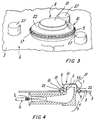
- a burner according to the invention is indicated overall by 1 and is associated with a cooking hob 2 having an upper surface 3 and a lower surface 4. Below the surface 4 there is present for the gas a conduit G carrying an injector J ( Figures 4, 5) and with which there is associated a usual venturi tube 5 which can lie horizontally ( Figure 4) or vertically ( Figure 5) or otherwise.
- the tube 5 (and the gas conduit in general) opens at its end 5A at 6 on the surface 3 of the hob 2.
- the burner 1 is present in a position corresponding with the opening 6.
- This burner comprises a burner body 8 having a base portion (or simply base) 9 and a one-piece head 10.
- the burner head 10 is positioned on the base 9 and lies vertically at a short distance from it by virtue of support feet 12 associated with said head.
- the support feet 12 can be associated with the base 9.
- an expansion chamber 15 into which there flows the gas/air mixture originating from the venturi tube 5 and created by entrainment of atmospheric air into this tube by the gas originating from the main.
- the burner base 9 and head 10 define within the burner body 8 an annular gap 16 provided laterally to this latter and presenting an inclination which can vary between horizontal and vertical.
- the gap 16 communicates with the expansion chamber 15.
- a substantially uninterrupted annular flame 17 forms at said gap when the burner is activated, said flame thus appearing along the peripheral edge of the burner body 8.
- the flame can also appear along an inner peripheral edge of the burner body 8 along another gap communicating with the chamber 15.
- the burner head 10 is substantially of flanged inverted cup shape, comprising a central portion 21 and a peripheral flange 22 positioned below the portion 21. This portion is hollow and is superposed on the opening 6 of the venturi tube 5.
- the lower face 22A of the flange 22 is inclined to the surface 3 of the hob 2 and faces, at a distance therefrom, a corresponding face 25A of an edge 25 of the burner base 9.
- This latter comprises a frusto-conical central part 26 surrounding that terminal part 5A of the venturi tube 5 projecting from the hob 2.
- the burner head 10 has a very small height above the surface 3 of the cooking hob 2, enabling this latter to comprise integrated supports of various shapes (defining the usual "grid") for a food preparation utensil or pan. These supports are shown in Figure 3 where they are indicated by 27.
- Usual flame generation and control members can be associated with the burner of the invention.
- a spark generator 30 can be associated with the base 9 together with a usual thermocouple 31 to maintain gas feed to the burner in known manner after the flame 17 has been activated.
- the gas/combustion air mixture can be adjusted by modifying the dimension (aperture) of the gap 16 by changing the distance between the burner head 10 and base 9.
- This can be achieved by moving the head relative to the base; for example (see Figure 1), with the base 9 there can be associated supports 33 movable parallel to the terminal part 5A of the venturi tube 5 and arranged to cooperate with the feet 12 of the head 10.
- the supports 33 are associated with rods 34 movable parallel to the axis K and cooperating with cams 35 provided on a rotary member 36 parallel to the surface 4 of the hob 2 and positioned below it.
- This member 36 is mounted on a rotary shaft 37 driven by a motor 38 the operation of which is controlled by a pushbutton 39 mounted in a suitable position on the hob 2.
- Rotation of the shaft 37 about its axis results in rotation of the member 36 and hence possible cooperation between the cams 35 and the rods 34 which raise the supports 33 from the burner base 9, to hence cause the head 10 to rise from the base 9. This results in modification of the width of the gap 16.
- the cams 35 can also be provided directly on the burner base 9 in a predetermined position to hence allow pre-adjustment of the width of the gap 16 prior to the use of the burner 1.
- the head 10 presents a lower annular part 43 resting on the burner base 9 and provided with a plurality of longitudinally or transversely (with respect to the head 10) extending slots.
- the slots are equidistant and the gas/air mixture emerges from them. As these slots are spaced from the peripheral edge of the burner body 8, igniting the mixture results in the generation of a continuous annular flame about the burner 1.
- the burner of the invention having a continuous single flame, and being provided with a diffuser with slots or cavities for flame stabilization, producers a flame front of laminar type which in its turn generates a noise which is lower than that generated by known burners.
- the said burner has a very pleasing appearance and can be easily cleaned; because of its small height any pans placed on it are extremely stable.
- burner base 9 associated with a cooking hob (or other support surface or member).
- said base can be integrated into the cooking hob (which therefore comprises a region in which the occupying end 5A of the tube 5 is shaped as said base) or can be "virtual" in the sense of being that region (even completely flat, coplanar with the surface 6) of the cooking hob into which the tube opens and on which the burner head 10 is rested.
- a flame of continuous annular shape is generated.
Landscapes
- Engineering & Computer Science (AREA)
- Chemical & Material Sciences (AREA)
- Combustion & Propulsion (AREA)
- Mechanical Engineering (AREA)
- General Engineering & Computer Science (AREA)
- Gas Burners (AREA)
Abstract
Description
Claims (22)
- A gas burner associated with a support member such as a cooking hob (2) and comprising a burner body (8) positioned to correspond with and lying above a conduit (5) opening (at 6) onto a surface (3) of said support member (2), from said conduit there emerging a gas/air mixture, characterised in that said burner body (8) comprises at least one annular gap (16) at which a flame (17) is generated when the burner is activated.
- A gas burner as claimed in claim 1, characterised in that the annular gap (16) is provided on a lateral surface of the burner body (8).
- A gas burner as claimed in claim 1, characterised in that the flame (17) generated by the burner is continuous.
- A gas burner as claimed in claim 1, characterised in that the burner body (8) comprises a base portion (9) containing the opening (6) of said conduit (5) and on which there is positioned, spaced therefrom, a burner head (10), between said burner head (10) and said base portion (9) there being defined the gap (16) through which an annular flame emerges when the burner is activated.
- A gas burner as claimed in claim 1, characterised in that the burner head (10) is in one piece.
- A gas burner as claimed in claim 2, characterised in that the burner head is cup shaped and presents a flange (22) at its free end, the hollow portion (21) of the head (20) being superposed on the opening (6) of the conduit (5) for the gas/air mixture.
- A gas burner as claimed in claim 3, characterised in that the burner head (10) carries spacer elements (12) arranged to maintain it spaced from the base portion (9).
- A gas burner as claimed in claim 3, characterised in that the flange (22) of the burner head (10) is inclined to the support member (2) with which the burner body (8) is associated.
- A gas burner as claimed in claim 1, characterised in that the base portion (9) of the burner (1) is flared.
- A gas burner as claimed in claims 5 and 6, characterised in that the base portion (9) of the burner (1) presents a peripheral part (25) having a portion (25A) inclined to the surface (3) of the support member (2), said portion (25A) being arranged to face the inclined flange of the burner head (10), and a frusto-conical part (26) surrounding the opening (6) of the conduit (5) for the gas/air mixture.
- A gas burner as claimed in claim 1, characterised by comprising means (33, 34, 35, 36, 37, 38, 39) for modifying the distance between the head (10) and the base portion (9) of the burner (1), said modification varying the width of the lateral gap (16) in the burner body (8), through which the annular flame is generated.
- A gas burner as claimed in claim 11, characterised in that the means for modifying the distance between the head (10) and the base portion (9) of the burner (1) are elements (33) associated with and movable relative to the base portion (9), and arranged to cooperate with spacer elements (12) of the head (10), said elements cooperating, via linkages (34), with cams (35) carried by a rotary member (36) positioned below the support member (2) and connected to a selectively operable actuator (38).
- A gas burner as claimed in claim 1, characterised in that the base portion (9) is an independent member separate from the support member (2) with which the burner (1) is associated.
- A gas burner as claimed in claim 1, characterised in that the base portion (9) is a region of the support member (2) with which the burner (1) is associated, and in which the conduit for the gas/air mixture opens.
- A gas burner as claimed in claim 1, characterised in that the base portion (9) carries an igniter (30) and a flame sensor (31).
- A gas burner as claimed in claim 1, characterised in that the burner head (10) presents a skirt (43) which surrounds the opening (6) of the conduit (5) for the gas/air mixture and is provided with through apertures (44).
- A gas burner as claimed in claim 1, characterised in that the burner body (8) comprises two concentric annular gaps.
- A cooking hob comprising at least one gas burner (1) having a burner body (8), said hob (2) having an upper surface (3) and a lower surface (4), into the upper surface there opening a conduit (5) for the gas/air mixture, the burner body (8) being positioned at the opening (6) of the conduit (5) on the hob (2), characterised in that the burner body (8) comprises at least one annular gap (16) through which the annular flame emerges.
- A cooking hob as claimed in claim 1, characterised in that the annular gap (16) is present on a lateral surface of the burner body (8).
- A cooking hob as claimed in claim 18, characterised in that the annular gap (16) is provided between a burner head (10) and a base portion (9) which are relatively removable, said portion containing the opening (6) of the conduit (5) for the gas/air mixture.
- A cooking hob as claimed in claim 20, characterised in that the burner base portion (9) is independent of the cooking hob.
- A cooking hob as claimed in claim 20, characterised in that the burner base portion (9) is a part of the cooking hob.
Applications Claiming Priority (2)
| Application Number | Priority Date | Filing Date | Title |
|---|---|---|---|
| IT2000MI001302A IT1317784B1 (en) | 2000-06-09 | 2000-06-09 | GAS BURNER GENERATING AN ANULAR FLAME |
| ITMI001302 | 2000-06-09 |
Publications (2)
| Publication Number | Publication Date |
|---|---|
| EP1162404A2 true EP1162404A2 (en) | 2001-12-12 |
| EP1162404A3 EP1162404A3 (en) | 2002-08-21 |
Family
ID=11445235
Family Applications (1)
| Application Number | Title | Priority Date | Filing Date |
|---|---|---|---|
| EP01106681A Withdrawn EP1162404A3 (en) | 2000-06-09 | 2001-03-16 | Gas burner generating an annular flame |
Country Status (2)
| Country | Link |
|---|---|
| EP (1) | EP1162404A3 (en) |
| IT (1) | IT1317784B1 (en) |
Cited By (3)
| Publication number | Priority date | Publication date | Assignee | Title |
|---|---|---|---|---|
| US6589046B2 (en) * | 2001-08-21 | 2003-07-08 | Uwe Harneit | Gas burner for outdoor cooking |
| ITTO20110126A1 (en) * | 2011-02-14 | 2012-08-15 | Indesit Co Spa | GAS BURNER, IN PARTICULAR FOR A HOUSEHOLD APPLIANCE |
| ITMI20111471A1 (en) * | 2011-08-01 | 2013-02-02 | Smeg Spa | GAS BURNER FOR A COOKTOP AND A COOKTOP INCLUDING THIS GAS BURNER |
Family Cites Families (9)
| Publication number | Priority date | Publication date | Assignee | Title |
|---|---|---|---|---|
| US2179951A (en) * | 1938-05-14 | 1939-11-14 | Petersen George | Gas stove burner |
| FR1313704A (en) * | 1957-10-24 | 1963-01-04 | Liotard Metallurg | Burner for heater |
| DE2649454A1 (en) * | 1976-10-29 | 1978-05-03 | Ruhrgas Ag | COOKING BURNER FOR GAS COOKERS |
| FR2620199B1 (en) * | 1987-09-08 | 1992-02-28 | Sourdillon Airindex Sa | IMPROVEMENTS ON PILOT FLAME GAS BURNERS AND BURNER CAP FOR SUCH IMPROVED BURNERS |
| GB8825817D0 (en) * | 1988-11-04 | 1988-12-07 | Parkinson Cowan Appliances Ltd | Gas burner |
| GB9417082D0 (en) * | 1994-08-24 | 1994-10-12 | Univ Leeds Innovations Ltd | A burner for gas cookers and hobs |
| DE19751008C1 (en) * | 1997-11-18 | 1999-04-22 | Metallwaren Heidersdorf Gmbh | Gas burner for cooker |
| DE29805620U1 (en) * | 1998-03-27 | 1998-05-14 | Schott Glas, 55122 Mainz | Hob with a gas burner |
| US6135764A (en) * | 1998-04-09 | 2000-10-24 | Kwiatek; David J. | Ribbon port burner for gas range |
-
2000
- 2000-06-09 IT IT2000MI001302A patent/IT1317784B1/en active
-
2001
- 2001-03-16 EP EP01106681A patent/EP1162404A3/en not_active Withdrawn
Cited By (4)
| Publication number | Priority date | Publication date | Assignee | Title |
|---|---|---|---|---|
| US6589046B2 (en) * | 2001-08-21 | 2003-07-08 | Uwe Harneit | Gas burner for outdoor cooking |
| ITTO20110126A1 (en) * | 2011-02-14 | 2012-08-15 | Indesit Co Spa | GAS BURNER, IN PARTICULAR FOR A HOUSEHOLD APPLIANCE |
| EP2487413A1 (en) * | 2011-02-14 | 2012-08-15 | Indesit Company, S.p.A. | Gas burner, in particular for a household cooking appliance |
| ITMI20111471A1 (en) * | 2011-08-01 | 2013-02-02 | Smeg Spa | GAS BURNER FOR A COOKTOP AND A COOKTOP INCLUDING THIS GAS BURNER |
Also Published As
| Publication number | Publication date |
|---|---|
| EP1162404A3 (en) | 2002-08-21 |
| ITMI20001302A1 (en) | 2001-12-09 |
| IT1317784B1 (en) | 2003-07-15 |
| ITMI20001302A0 (en) | 2000-06-09 |
Similar Documents
| Publication | Publication Date | Title |
|---|---|---|
| US3592180A (en) | Gas burner device | |
| US8746229B2 (en) | Gas burner system for food cooking appliances | |
| US5139417A (en) | Gas burner with improved primary port arrangement | |
| AU2001262598B2 (en) | Burner with internal separator | |
| EP0797048B1 (en) | Gas burner for kitchen appliances | |
| HK1038959A1 (en) | Gas burner with multiple ring flames | |
| MX2007000535A (en) | A gas heating appliance. | |
| US11512854B2 (en) | Gas cooking assembly and a hob comprising the same | |
| US5546853A (en) | Barbecue grill with fluidic burner and heat distribution system | |
| EP1249665B1 (en) | Gas burner and cooktop provided with such gas burner | |
| CN121677012A (en) | Cookware support, gas cooker and method for producing cookware support | |
| US11359818B2 (en) | Gas burner | |
| EP3809041B1 (en) | Gas cooktop burner assembly | |
| CN100472133C (en) | Three ring top type gas burner | |
| FR2694377A1 (en) | Gas cooking appliance with atmospheric gas burners. | |
| US6131561A (en) | Burner with secondary air stability ring | |
| US2649850A (en) | Top burner assembly, including a flash tube lighter for cooking stoves or ranges | |
| US6435173B1 (en) | Combined burner and grate | |
| GB1569810A (en) | Gas cooking unit | |
| EP1018622B1 (en) | Burner for portable gas cooking stove | |
| JPH094853A (en) | Gas hot plate | |
| US10690351B2 (en) | Home cooking appliance having a pedestal burner | |
| JP2000083835A (en) | Radiant heating device for roastor | |
| WO2007068659A1 (en) | A cooking device | |
| US4907568A (en) | Downdraft barbecue |
Legal Events
| Date | Code | Title | Description |
|---|---|---|---|
| PUAI | Public reference made under article 153(3) epc to a published international application that has entered the european phase |
Free format text: ORIGINAL CODE: 0009012 |
|
| AK | Designated contracting states |
Kind code of ref document: A2 Designated state(s): AT BE CH CY DE DK ES FI FR GB GR IE IT LI LU MC NL PT SE TR |
|
| AX | Request for extension of the european patent |
Free format text: AL;LT;LV;MK;RO;SI |
|
| PUAL | Search report despatched |
Free format text: ORIGINAL CODE: 0009013 |
|
| AK | Designated contracting states |
Kind code of ref document: A3 Designated state(s): AT BE CH CY DE DK ES FI FR GB GR IE IT LI LU MC NL PT SE TR |
|
| AX | Request for extension of the european patent |
Free format text: AL;LT;LV;MK;RO;SI |
|
| 17P | Request for examination filed |
Effective date: 20030211 |
|
| AKX | Designation fees paid |
Designated state(s): DE ES FR GB IT SE |
|
| 17Q | First examination report despatched |
Effective date: 20030417 |
|
| STAA | Information on the status of an ep patent application or granted ep patent |
Free format text: STATUS: THE APPLICATION IS DEEMED TO BE WITHDRAWN |
|
| 18D | Application deemed to be withdrawn |
Effective date: 20031028 |