EP1162386A1 - Impact energy absorbing member - Google Patents
Impact energy absorbing member Download PDFInfo
- Publication number
- EP1162386A1 EP1162386A1 EP00981739A EP00981739A EP1162386A1 EP 1162386 A1 EP1162386 A1 EP 1162386A1 EP 00981739 A EP00981739 A EP 00981739A EP 00981739 A EP00981739 A EP 00981739A EP 1162386 A1 EP1162386 A1 EP 1162386A1
- Authority
- EP
- European Patent Office
- Prior art keywords
- impact energy
- energy absorption
- absorption member
- impact
- long
- Prior art date
- Legal status (The legal status is an assumption and is not a legal conclusion. Google has not performed a legal analysis and makes no representation as to the accuracy of the status listed.)
- Granted
Links
Images


Classifications
-
- F—MECHANICAL ENGINEERING; LIGHTING; HEATING; WEAPONS; BLASTING
- F16—ENGINEERING ELEMENTS AND UNITS; GENERAL MEASURES FOR PRODUCING AND MAINTAINING EFFECTIVE FUNCTIONING OF MACHINES OR INSTALLATIONS; THERMAL INSULATION IN GENERAL
- F16F—SPRINGS; SHOCK-ABSORBERS; MEANS FOR DAMPING VIBRATION
- F16F7/00—Vibration-dampers; Shock-absorbers
-
- B—PERFORMING OPERATIONS; TRANSPORTING
- B60—VEHICLES IN GENERAL
- B60J—WINDOWS, WINDSCREENS, NON-FIXED ROOFS, DOORS, OR SIMILAR DEVICES FOR VEHICLES; REMOVABLE EXTERNAL PROTECTIVE COVERINGS SPECIALLY ADAPTED FOR VEHICLES
- B60J5/00—Doors
- B60J5/04—Doors arranged at the vehicle sides
- B60J5/042—Reinforcement elements
- B60J5/0422—Elongated type elements, e.g. beams, cables, belts or wires
- B60J5/0438—Elongated type elements, e.g. beams, cables, belts or wires characterised by the type of elongated elements
- B60J5/0441—Elongated type elements, e.g. beams, cables, belts or wires characterised by the type of elongated elements the elements having a grid-like structure, i.e. interconnected or interwoven elements
-
- B—PERFORMING OPERATIONS; TRANSPORTING
- B60—VEHICLES IN GENERAL
- B60J—WINDOWS, WINDSCREENS, NON-FIXED ROOFS, DOORS, OR SIMILAR DEVICES FOR VEHICLES; REMOVABLE EXTERNAL PROTECTIVE COVERINGS SPECIALLY ADAPTED FOR VEHICLES
- B60J5/00—Doors
- B60J5/04—Doors arranged at the vehicle sides
- B60J5/042—Reinforcement elements
- B60J5/0422—Elongated type elements, e.g. beams, cables, belts or wires
- B60J5/0438—Elongated type elements, e.g. beams, cables, belts or wires characterised by the type of elongated elements
- B60J5/044—Elongated type elements, e.g. beams, cables, belts or wires characterised by the type of elongated elements the elements being flexible, e.g. belts, cables or wires
-
- B—PERFORMING OPERATIONS; TRANSPORTING
- B60—VEHICLES IN GENERAL
- B60R—VEHICLES, VEHICLE FITTINGS, OR VEHICLE PARTS, NOT OTHERWISE PROVIDED FOR
- B60R19/00—Wheel guards; Radiator guards, e.g. grilles; Obstruction removers; Fittings damping bouncing force in collisions
-
- F—MECHANICAL ENGINEERING; LIGHTING; HEATING; WEAPONS; BLASTING
- F16—ENGINEERING ELEMENTS AND UNITS; GENERAL MEASURES FOR PRODUCING AND MAINTAINING EFFECTIVE FUNCTIONING OF MACHINES OR INSTALLATIONS; THERMAL INSULATION IN GENERAL
- F16F—SPRINGS; SHOCK-ABSORBERS; MEANS FOR DAMPING VIBRATION
- F16F1/00—Springs
- F16F1/36—Springs made of rubber or other material having high internal friction, e.g. thermoplastic elastomers
- F16F1/366—Springs made of rubber or other material having high internal friction, e.g. thermoplastic elastomers made of fibre-reinforced plastics, i.e. characterised by their special construction from such materials
-
- F—MECHANICAL ENGINEERING; LIGHTING; HEATING; WEAPONS; BLASTING
- F16—ENGINEERING ELEMENTS AND UNITS; GENERAL MEASURES FOR PRODUCING AND MAINTAINING EFFECTIVE FUNCTIONING OF MACHINES OR INSTALLATIONS; THERMAL INSULATION IN GENERAL
- F16F—SPRINGS; SHOCK-ABSORBERS; MEANS FOR DAMPING VIBRATION
- F16F1/00—Springs
- F16F1/36—Springs made of rubber or other material having high internal friction, e.g. thermoplastic elastomers
- F16F1/42—Springs made of rubber or other material having high internal friction, e.g. thermoplastic elastomers characterised by the mode of stressing
- F16F1/422—Springs made of rubber or other material having high internal friction, e.g. thermoplastic elastomers characterised by the mode of stressing the stressing resulting in flexion of the spring
- F16F1/426—Radial flexion of ring-type springs
-
- F—MECHANICAL ENGINEERING; LIGHTING; HEATING; WEAPONS; BLASTING
- F16—ENGINEERING ELEMENTS AND UNITS; GENERAL MEASURES FOR PRODUCING AND MAINTAINING EFFECTIVE FUNCTIONING OF MACHINES OR INSTALLATIONS; THERMAL INSULATION IN GENERAL
- F16F—SPRINGS; SHOCK-ABSORBERS; MEANS FOR DAMPING VIBRATION
- F16F7/00—Vibration-dampers; Shock-absorbers
- F16F7/12—Vibration-dampers; Shock-absorbers using plastic deformation of members
Definitions
- the present invention relates to an impact energy absorption member used to absorb impact energy to prevent the damage of transportation equipment by absorbing impact energy generated in the collision thereof, the transportation equipment including vehicles such as a passenger car, a track, and the like, airplanes such as a passenger plane and the like, vessels such as a fishing boat, a ferry boat, and the like, railroad cars such as an electric car, a monorail car, and the like.
- the transportation equipment including vehicles such as a passenger car, a track, and the like, airplanes such as a passenger plane and the like, vessels such as a fishing boat, a ferry boat, and the like, railroad cars such as an electric car, a monorail car, and the like.
- Transportation equipment such as vehicles, motor cars, and the like which has a possibility of collision while it moves is provided with an impact energy absorption mechanism for protecting an equipment main body and the life of crews from the impact generated in the collision.
- a hollow metal frame, a polymer- formed material, and so on, for example, have been used as a conventional impact energy absorption member.
- a mechanism in which the conventional impact energy absorption member absorbs energy is such that a metal- or polymer-formed material receives an impact force, is deformed by compression or bending, and absorbs impact energy through the subsequent plastic deformation or breakage thereof.
- Japanese Unexamined Patent Application Publication No. 9-2178 proposes an impact absorption structure for the interior member of motor cars for absorbing impact by that a rib portion is pressed and deformed by being bent.
- the publication exhibits characteristics such as an elastic modulus in bending, Izod strength, and the like.
- Japanese Unexamined Patent Application Publication No. 9-95197 proposes an energy absorption structure for the side portion of a vehicle body capable of effectively absorbing energy in such a manner that a rib portion is elastically deformed and a load sequentially increases accordingly.
- the publication further describes a shape having a hollow portion.
- Japanese Unexamined Patent Application Publication No. 5-32147 proposes an impact energy absorption member for a bumper using a fiber-reinforced composite material.
- the mechanism of the composite material is such that when the material is deformed by compression, it is exfoliated and broken so that energy to be absorbed thereby increases.
- the conventional impact energy absorption members utilize plastic deformation and breakage due to compression as described above, the wall thickness of a member cannot help being increased, that is, the member cannot help being formed in a bulky shape such as a hollow shape together with an increased wall thickness in order to absorb a large amount of energy which is generated in collision at a high speed.
- these conventional impact energy absorption members are disadvantageous in that the space of a cabin of transportation equipment is reduced and the dwelling property thereof is scarified and further the overall weight of the impact energy absorption members increases and gas mileage is lowered, which is undesirable from an economical and environmental viewpoint.
- the transportation equipment is required to greatly reduce its weight from the view point of administration for protecting environment.
- a sophisticated composite material that is, a fiber-reinforced composite material (hereinafter, abbreviated as FRP) that seems to greatly reduce a weight and to improve durability as a material to be replaced with a metal material.
- FRP fiber-reinforced composite material
- the FRP is a material that does not almost exhibit plastic deformation and has compression and bending strength which is almost the same as that of the metal material while the FRP has tensile strength that is larger than that of the metal material. Therefore, it is difficult to actually use the FRP at present because the FRP does not have a sufficient merit in the reduction of weight in the conventional impact energy absorbing mechanism which is broken in the compression and bending modes.
- a first object of the present invention is to provide a light and compact impact energy absorption member that makes use of the aforementioned bending and compression modes and can eliminate the drawbacks of the conventional heavy and bulky impact energy absorption member for transportation equipment and sufficiently absorb impact energy from a moving body in the occurrence of collision.
- a second object of the present invention is to provide a means for solving the above problem.
- An impact energy absorption member of the present invention is characterized by comprising a long member of fiber reinforced resin having a lengthwise direction and a thickness direction, wherein the ratio(t/L) of the thickness t (mm) of the long member to the length L (mm) thereof is within the range of 1/11000 to 6/1000 as well as the direction of an external force is substantially in agreement with the thickness direction of the impact member.
- the impact energy absorption member of the present invention When used, it is jointed and fixed mechanically and/or through bonding to portions where the member is desired to absorb impact energy such as the insides of a door and a bumper, the inner surface and the external surface of a side panel, the rear portion of an engine, the periphery of a cabin for crews, and the like.
- FIG. 1 is a perspective view showing an embodiment of an FRP impact energy absorption member according to the present invention.
- the impact energy absorption member of the present invention is composed of an FRP long member having a lengthwise direction and a thickness direction.
- the long member 1 is a generic term representing members formed in a so-called sheet-shape, rope-shape, belt shape, and the like which are long with respect to a sectional area. Almost all the cross sections (lateral cross sections), which are perpendicular to a lengthwise direction, of these shapes are liable to generate tension against an impact force. Of these members, the sheet-shaped member is particularly preferable.
- the lengthwise direction 2 literally means a direction in which the length of the long member is maximized, and the length is several tens of centimeters to several meters when it is a member used for motor cars.
- the lengthwise direction is not in coincidence with a direction of the impact force, and the impact force is vertical to the lengthwise direction or has a certain angle thereto ( ⁇ of FIG. 5 to be described later).
- the thickness direction 3 is a direction approximately vertical to the lengthwise direction and in approximate agreement with a direction in which the long member is most deformed when it is subjected to the impact force. That is, the impact force itself is caused to be in substantial agreement with the thickness direction by tension even if it is not vertical to the lengthwise direction of the long member.
- the FRP in the present invention is a fiber simple body which is composed of reinforcing fibers such as carbon fibers, aramid fibers, glass fibers, and the like and formed in a braided-string-shape or in a twisted- fiber-shape or the fiber simple body partly impregnated with resin.
- the ratio (t/L) of the thickness t (mm) to the length (L) of the long member is within the range of 1/11000 to 6/1000.
- a so-called sheet-shaped member having a thin thickness is preferable.
- the impact energy absorption member of the present invention is disposed so that the direction in which the impact force acts is in substantial agreement with the thickness direction.
- the impact energy absorption member of the present invention since the impact energy absorption member of the present invention has a long size and a thin wall thickness, even if the impact force acts thereon, it is not broken by being bent or compressed so that it can absorb energy until it is broken by being extended (for example, as shown in the embodiment, when a carbon-fiber-reinforced composite material (hereinafter, abbreviated as "CFRP") is compared with a high tension steel, the amount of energy absorbed by the CFRP is about ten times as large as that absorbed by the high tension steel and further the specific gravity of the CFRP is about one fifth that of the high tension steel, thus the CFRP has a very high weight reducing effect.). Breakage may be caused by elongation even at a value smaller than the above lower limit value.
- CFRP carbon-fiber-reinforced composite material
- the long member when used as a member for transportation equipment, the absolute value of the amount of energy absorbed by the member is not sufficient in this case. Further, the long member is not always broken by being extended even at a value larger than the above upper limit value.
- the above ratio t/L is preferably 1/11000 to 3/1000, more preferably 1/4000 to 3/1000 and most preferably 1/3000 to 2/1000.
- the impact energy absorption member of the present invention is a member substantially the entire cross section of which is deformed by being extended when it is tested by a pendulum impact test method which will be described later.
- the pendulum impact test method mentioned in the present invention is a scaled-up Charpy test method (refer to JIS-7111 and ISO-179).
- the endless long member 1 is stretched around pins 4 acting as fixing jigs fixed to a not shown highly rigid frame without looseness (pretension of 0. 1 to 1 Kg is applied to the long member 1).
- the pins at both the ends of the four pins have an interval L1 which is equal to the length (entire span) of the long member, and the remaining two pins have an interval L2 which is 80% of the entire span.
- the entering angle ⁇ of the pendulum in this case is within the range of 30 to 90°.
- the entering angle can be set by adjusting the positions of a frame and the cone.
- the amount of absorbed energy is calculated by a method of an ordinary Charpy test from the height to which the pendulum rises after it applies impact to the long member 1.
- the height to which the pendulum rises also can be determined by recording the state of the pendulum by a video camera.
- the connecting members are composed of a FRP having high strength or a metal material. Further, when the long member is too long, the length thereof can be adjusted by suitably cutting it.
- the long member 1 of the present invention be deformed by being extended in the lengthwise direction (extended) and tensile stress occur in approximately the entire cross section (cross section perpendicular to the lengthwise direction, that is, lateral cross section). That is, the long member is deformed in a direction where the length thereof increases on the side thereof where impact is applied as well as on the side opposite to the above side in the pendulum impact test.
- the long member is deformed by being bent, an impacted side is compressed and an opposite side is extended.
- Whether or not the long member is deformed by being extended can be confirmed by directly bonding a strain gauge thereon and monitoring a change of strain while impact is applied to the long member. Further, whether or not the long member is broken by being extended can be confirmed by identifying a broken surface by fractography. In the FRP, a surface broken by elongation exhibits an aspect of great irregularity in which many fibers are fallen out and pulled out.
- the impact energy absorption member of the present invention have an amount of energy absorbed per unit weight of at least 3.9 J/g in the above pendulum impact test.
- the impact energy absorption member of the present invention has the amount of energy absorbed per unit weight of at least 3.9 J/g, it is made suitable for transportation equipment and the like that are closely related to gas mileage.
- the impact energy absorption member of the present invention can absorb energy per unit weight in an amount several times larger than that of the metal material. Note that the proper upper limit range of the amount of energy absorbed per unit weight of materials that can be used for the transportation equipment is about 50 J/g from a view point of cost.
- the amount of energy absorbed per unit volume is suitably within the range of 5 to 40 J/cm 3 . Setting the amount within this range permits the effective space in the transportation equipment to increase as well as the cost of the impact energy absorption member to be accepted by the transportation equipment, which makes the impact energy absorption member more preferable.
- FIG. 1 is a view showing a thin sheet member acting as an embodiment of the long member 1.
- the sheet member has a length L (mm), a width B (mm) and a thickness t (mm) and further has a lengthwise direction denoted by reference numeral 2 and a thickness direction denoted by reference numeral 3.
- An impact load acts approximately in the thickness direction, that is, in a direction approximately vertical to the longitudinal direction or at an angle ⁇ (within the range of 30 to 90°) with respect to the longitudinal direction.
- the length, width, and thickness of the long member 1 need not be always uniform. When the length, width, and thickness are not uniform, however, they will be represented by average values.
- the FRP in the present invention means fiber-reinforced resin containing reinforcing fibers and matrix resin.
- the reinforcing fibers mainly bear the tensile load generated in a sheet member, and it is not always necessary for the resin to cover all the fibers. That is, the FRP may has portions composed only of the reinforcing fibers.
- the portions composed only of the reinforcing fibers has a feature that they are very flexible and can be deformed along portions having a complex shape.
- fibers including inorganic fibers such as carbon fibers, glass fibers, alumna fibers, silicon nitride fibers, etc.; polyamide synthetic fibers such as aramid fibers, nylon, etc.; organic fibers such as aramid fibers, PBO (polybenzoxazine) fibers, polyolefin fibers, polyester fibers, polyphenyl sulfon fibers; and the like. These fibers can be used independently or in a mixture of at least two kinds thereof.
- the carbon fibers are particularly useful because they have high strength and high elastic modulus and are excellent in corrosion resistance.
- the carbon fibers may be any of PAN (polyacrylnitrile) carbon fibers and pitch carbon fibers. Among them, however, PAN carbon fibers are preferable because they have a wide variation of the aforementioned elongation.
- PAN carbon fibers are preferable because they have a wide variation of the aforementioned elongation.
- the carbon fibers can be preferably used because they have a less amount of creep deformation among the reinforcing fibers.
- the disposition of the carbon fibers in the direction of tension permits impact energy to be effectively absorbed.
- the carbon fibers have a diameter of 5 to 15 ⁇ m to effectively exert tensile strength.
- glass fibers in particular, fiber-like glass such as E glass, C glass, S glass, etc.
- fibers have a diameter of 5 to 15 ⁇ m in consideration of creep characteristics.
- the fiber diameter is larger than this range, creeps are liable to be generated by a flaw on a surface. Further, the fiber diameter outside of this range reduces productivity.
- Aramid fibers that have high elongation and strength are preferably used as the organic fibers. This is because that the aramid fibers have resistance to acid that is often used in the transportation equipment as well as have very high strength of 2.5 to 3.8 GPa so that impact energy can be absorbed with a small amount of them. Widely used as the aramid fibers are Kevlar fibers. Since the specific gravity of the Kevlar fibers is smaller than those of the carbon fibers and the glass fibers, it can be used also when it is desired to reduce the weight of the impact energy absorption member.
- the weight of the impact energy absorption member can be more reduced.
- the organic fibers are nonconductive similar to the glass fibers, covering the carbon fibers,with the organic fibers can entirely or partly make the surface of the impact energy absorption member nonconductive.
- any known shape such as a stand shape, a lobing shape, a spun-yarn shape, a woven-shape, a covering yarn shape may be employed as the shape of the fibers.
- the strand shape and the lobing shape are preferable to obtain an impact energy absorbing capability, that is, high tensile characteristics.
- the rope and the like disclosed in Japanese Unexamined Patent Application Publication No. 11-302978 are also preferable shapes.
- the reinforcing fibers used in the impact energy absorption member of the present invention are disposed in a lengthwise direction of a sheet to absorb impact energy by tensile deformation.
- the direction in which they are disposed need not be in strict agreement with the lengthwise direction.
- the reinforcing fibers are disposed with a tilt of about ⁇ 5° with respect to the axis of the sheet in the lengthwise direction, they are regarded as being substantially disposed in the lengthwise direction when they are broken by a tension mode. Nevertheless, fibers that are disposed in directions other than the longitudinal direction may be contained for the convenience of formation from the view point of productivity.
- the ratio of the reinforcing fibers disposed in the lengthwise direction to all the reinforcing fibers is preferably 70% or more and more preferably 80 % or more.
- organic fibers and glass fibers may be disposed at portions in contact with a forming metal mold to reduce the wear thereof.
- the application of twist of about 2 times/m to 10 times/m has an effect for suppressing breakage of strings, and this is preferable in processing.
- the reinforcing fibers are contained preferably in an amount of 35 to 99 vol% and more preferably in an amount of 50 to 90 vol%. Note that the fiber content can be measured according to JIS K7052.
- thermosetting resins such as epoxy resins, vinyl ester resins, unsaturated polyester resins, phenol resins, benzoxazine resins, etc.
- thermoplastic resins such as polyethylene resins, polyamide resins, polypropylene resins, ABS resins, polybutylene telephthalate resins, polyacetal resins, polycarbonate resins, etc., and denatured resins obtained by making these resins to alloys.
- Polyvinyl chlorides are preferable because they are excellent in a low temperature performance.
- the epoxy resins, the polyester resins, vinyl ester resins, and the denatured resins thereof can be preferably used as a material for the field of the transportation equipment because they are excellent in draw forming property as well as in chemical and weather resistance. Further, the phenol resins and the benzoxazine resins are preferable because they are excellent in noncombustibility and generate a less amount of gas when they are burnt.
- thermoplastic resins such as the polypropylene resins and the like can preferably be used.
- the object of the matrix resins is not to exert compression strength
- rubber-like matrix resins having an elastic modulus of about 20 MPa may be used.
- the elastic modulus of the matrix resins is within the range of 100 to 600 Mpa.
- the long member of the present invention may be of a sheet shape, a rope shape (FIG. 6), a belt shape, a wire shape, a chain shape, a net shape(FIG. 7), and a thin sheet shape as long as the entire cross section thereof is deformed by being extended in the aforementioned pendulum impact test.
- an amount of deformation larger than a certain degree is necessary from the meaning of absorbing a larger amount of impact energy and reducing an impact load applied to a crew.
- the curvature of the long member when it is bent be 1 m or less. This is because that since an amount of absorbed energy is the product of a load (P) and an amount of dislocation (S), when the amount of dislocation is made to one half in the absorption of the same amount of energy, the load is doubled.
- the curvature in bending can be measured by bending a member cut to 500 to 1000 mm at three points and geometrically determining the center of the curvature of the member from the photograph of the bent member.
- the impact energy absorption member of the present invention is disposed so that a direction in which an impact force acts is in agreement with the thickness direction of the member. This is because that when the impact force acts on the impact energy absorption member, tension, that is, a drawing force acts on fibers disposed in the lengthwise direction.
- fibers may be twisted each other (principle of rope) so as to increase the capability thereof for bearing a tensile load. More specifically, a rope, a belt, and a string-shaped material can be exemplified as this arrangement. Further, it is preferable that a sheet member form a closed loop to improve an energy absorption performance.
- the loop-shaped sheet member has a merit, as compared with a simply long sheet member the ends of which must be jointed to each other by bonding or mechanically, that the weight of which can be reduced because it does not need a jig for jointing the ends and that the weight of which is not increased by the reinforcement that is applied to the simple sheet in consideration of stress concentration. Further, the loop-shaped sheet also has a merit that a mounting job can be easily executed when it is assembled or repaired. Furthermore, the continuous disposition of reinforcing fibers along the loop permits tensile strength to be exerted ideally. As a result, the loop-shaped member has a merit that it can absorb impact energy in a very large amount.
- the width of the closed-loop-shaped sheet member need not be constant and may be tapered as in the absorption member shown in FIG. 4. Further, the closed-loop-shaped sheet member may be separated to a fork-shape at an end as in the absorption member shown in FIG. 3. More specifically, a net-shaped absorption member having a plurality of branched portions as in the absorption member shown in FIG. 7 and a gut-shaped absorption member having intersections are preferable.
- the transportation equipment In a case of, for example, a door of a motor car, there is a possibility that an impact force reaches a crew when collision occurs on a side of the motor car. From what is mentioned above, it is preferable in the transportation equipment that the tensile elongation in the lengthwise direction of the FRP constituting an FRP member be within the range of 0.3% to 3.5%. The tensile elongation is more preferably within the range of 0.5% to 3%. Note that the elongation of the FRP can be measured according to JIS K7054 or JIS K7074.
- the material having the suitable strength and elongation as described above are a carbon-fiber-reinforced composite material, a glass-fiber-reinforced composite material, and the like.
- reinforcing fibers having strength of at least 1.5 GPa are preferable because the strength of the fiber-reinforced composite material can be improved by a smaller amount of the reinforcing fibers.
- the impact energy absorption member of the present invention specifically find a wide range of uses in the general transportation equipment such as motor cars, which are generically called as an automobile, track, trailer, passenger car, sports car, racing car, motor tricycle, and the like as well as an airplane, motor bicycle, electric car, cargo, vessel and the like.
- motor cars which are generically called as an automobile, track, trailer, passenger car, sports car, racing car, motor tricycle, and the like as well as an airplane, motor bicycle, electric car, cargo, vessel and the like.
- one of preferable uses is a door for a motor car.
- the sheet-shaped FRP impact energy absorption member of the present invention is mounted to a portion where a steel pipe called an impact bar is conventionally mounted, it can absorb impact energy generated when collision occurred on a side of a motor car and protect a crew as well as reduce the weight of the door.
- the sheet member of FIG. 2 that is composed of a carbon-fiber-reinforced composite material having a thickness of 0.5 mm and a width of 100 mm and formed in a closed-loop-shape is fixed to the frame of a door.
- Fixing jigs such as pins or the like are used as a fixing method, and the fixing jigs are mechanically fixed to the frame as shown in FIG. 5. At this time, it is preferable that the frame be more rigid than a conventional frame.
- the impact energy absorption member may be fixed after pretension is applied thereto to reduce an amount of substances which are generated in collision and enter a cabin.
- the impact energy absorption member in the transportation equipment is installed between an engine room and a cabin for the purpose of preventing engine parts from entering the cabin (passenger's compartment) or installed in the vicinity of fuel parts such as a natural gas tank, hydrogen gas tank, gasoline tank, methanol tank, and so on for the purpose of preventing a fuel vessel from being damaged by an impact and causing fire and the like.
- fuel parts such as a natural gas tank, hydrogen gas tank, gasoline tank, methanol tank, and so on for the purpose of preventing a fuel vessel from being damaged by an impact and causing fire and the like.
- the portion where the impact energy absorption member is fixed to the frame rotatable to ease the stress concentration at the fixing portion so as to suppress the early breakage of the frame in the vicinity of the fixing portion.
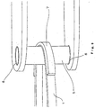
- a method of making the fixing portion rotatable there are a method of causing the member of the present invention to be in contact with a pin having a low coefficient of friction and making the member itself rotatable by lubricant (FIG. 8), a method of receiving a pin 6 fixed to a member by support members 6 each provided with a bearing to permit the member to be rotated together with the pin (FIG. 9), and the like.
- the fixed portion rotatable enables only tension to act more effectively, whereby a larger amount of energy can be absorbed. Further, it is effective for the increase of an amount of energy to be absorbed to increase the strength of the portion in the vicinity of the fixed portion of a long member by increasing the amount of the reinforcing fibers used in the long member or by partly reinforcing the long member (7 in FIG. 9).
- the partial reinforcement can be effectively applied to a portion where stress concentration is liable to occur such as a portion where a curvature increases, a portion where the long member comes into contact with other member, and the like.
- the impact energy absorption member of the present invention is the fiber-reinforced composite material
- the category thereof is very wide and includes not only the so-called FRP having high rigidity and strength used for structure but also composite materials used for a belt, rope, tire, and the like.
- a rope shape is preferable because it is excellent in an abrasion property (FIG. 6). More specifically, strand-shaped reinforcing fibers are arranged as a braided-cord-like fibers or a twisted fibers, and a rope is arranged by combining these fibers. In the case of the rope shape, an end the rope may be returned and caulked by metal fitting, may be subjected to SATSUMA-end knitting or the like, or may be fixed by being sewed with a sewing thread which is a method called stitching.
- the end of the rope may be processed by screw-end clamp, eye-end clamp, jaw-end clamp, SHINKO clamp, end supported socket clamp, open type socket, DINA anchor, and the like, similarly to a steel wire.
- the absorption member can be jointed to a vehicle body, a vehicle, and the like through a screw, which is suitable to assemble and disassemble them.
- a state without an end may be provided by forming a rope or the like to a loop.
- an impact energy absorption member formed in the loop shape it is also preferable to reinforce the overlapped portion thereof by caulking it with metal fitting or the like or by further winding reinforcing fibers around the overlapped portion so that the entire cross section of the absorption member can effectively bear a tensile load. It is needless to say that the amount of the reinforcing fibers is increased or decreased as necessary in portions other than the,overlapped portion to reduce the weight of the absorption member.
- the impact energy absorption member of the present invention fibers of high strength are subjected to breakage by tension that exhibits the highest energy absorbing efficiency so as to absorb energy generated when an impact is applied to the absorption member.
- the impact energy absorption member can be utilized also as an installation type energy absorption member for protecting the transportation equipment including motor cars as well as buildings and houses against which the transportation equipment may collide from an impact.
- a specific example is an energy absorption member which is used in place of a protection fence, a guard rail, and the like.
- the sheet-shaped impact energy absorption member of the present invention will be described.
- all the technologies including a filament winding method, a pulltrusion process, a pull/wind method, a hand lay up method, a resin transmolding method, and so on can be used.
- the pulltrusion process and the pull/wind methods are preferable because they can continuously manufacture a loop-shaped impact energy absorption member in which reinforcing fibers are disposed in the longitudinal direction of a sheet by using a tubular metal mold, disposing fibers in the radial direction of the tube and cutting the tube in round slices.
- the filament winding method also is a preferable forming method.
- reinforcing fibers or reinforcing fibers impregnated with matrix resin are wound around a mandrel having a cross section corresponding to a desired loop shape and then entirely, partly or additionally impregnated with matrix resin.' Subsequently, the matrix resin is hardened on the mandrel or after it is removed therefrom, thereby obtaining a tubular member. Further, the tubular member is cut in round slices having a necessary width to thereby obtain the impact energy absorption member of the present invention.
- a rope- and string-shaped impact energy absorption members can be manufactured in such a manner that reinforcing fiber strands or reinforcing fiber strands impregnated with resin are knitted or formed to a twisted structure using a braided-string manufacturing apparatus such as a braider, further a plurality of strands are twisted and impregnated with resin, and then the resin is hardened.
- FIG. 10 is a perspective view of a motor car 8 in which impact energy absorption members 1A to 1C of the present invention are used, wherein the impact energy absorption member 1A is used to absorb impact energy generated from a door; the impact energy absorption member 1B is used to absorb impact energy generated from an engine accommodated in an engine hood; and the impact energy absorption member 1C is used to absorb energy generated in rear-end collision.
- the impact energy absorption member 1A will be described in detail.
- FIG. 11 is a perspective view in which a door 9 in FIG. 10 is viewed from a cabin.
- the door 9 includes a pair of right and left rotatable bars 10 that are rotatably disposed on both the sides of the interior of the door 9 and the impact energy absorption member 1A of the present invention that is stretched between the pair of rotatable bars 10.
- FIG. 12 which is a sectional view in the direction of the arrow X-X of FIG. 11, the impact energy absorption member 1A is formed in an endless belt shape (the one shown in FIG. 2 described above) and stretched so as to surround the pair of rotatable bars 10.
- the impact energy absorption member 1A arranged as described above is disposed on the inner surface side of the door 9, if impact energy is applied by a traffic accident or the like in the direction of the cabin from the outside of the door, that is, if impact energy is applied in the direction of a white arrow in FIG. 12, first, the impact energy absorption member 1A receives the impact energy and converts it to cause the entire lateral cross section thereof that is perpendicular to the lengthwise direction thereof to be deformed by being extended.
- the impact energy is converted into the deformation due to elongation of the entire cross section of the absorption member, and the impact energy is resisted only by the tensile stress, different from a conventional impact energy absorption member that intends to absorb impact energy through the partial plastic deformation thereof.
- the impact energy absorption member 1A can absorb a very large amount of impact energy.
- the rotatable bars 10 rotate following the dislocation of the impact energy absorption member at the occurrence of collision and uniformly disperse locally applied impact energy to the entire cross section of the overall length of the end-belt-shaped impact energy absorption member 1A that has been deformed by being extended, whereby a larger amount of impact energy can be absorbed.
- Carbon fibers were used as reinforcing fibers, and the strands of "Toreca" T700S (elastic modulus: 235 GPa, strength: 5 GPa, elongation: 2.1%) supplied by Toray were impregnated with bisphenol A type epoxy resin and subjected to filament winding, and the resin was hardened in an oven at 130° for 2 hours. With this processing, impact energy absorption members each composed of a closed-loop-shaped FRP sheet member (containing the carbon fibers in the amount of 60 vol%) were obtained. Each absorption member had a width of 50 mm, a thickness of 0.3 mm, and a length of 100 mm. The tensile strength of these members was 2700 Mpa, and the elongation thereof was 2.1%.
- Ropes each having a thickness of 5 mm were manufactured by way of trial by twisting aramid fibers (Kevlar 49) of 3000 denier. Then, long members each having a length of 1000 mm were manufactured by bending both the ends of the ropes in a loop shape, impregnating the loop portions with room-temperature-hardening- type epoxy resin, caulking both the ends with steel fitting of 1 mm thick, and hardening the epoxy resin. Subsequently, when each long member was mounted on the pendulum impact tester and tested similarly to the example 1, it was broken by being extended. At that time, the value of energy absorbed per unit weight was 5.5 J/g.
- a very superior and conventionally unobtainable impact energy absorption member that is easily broken in a tension mode and excellent in impact energy absorbing characteristics regardless of that it is light in weight can be obtained, whereby a member for transportation equipment that is excellent in impact resistance can be obtained.
Landscapes
- Engineering & Computer Science (AREA)
- General Engineering & Computer Science (AREA)
- Mechanical Engineering (AREA)
- Health & Medical Sciences (AREA)
- Child & Adolescent Psychology (AREA)
- Textile Engineering (AREA)
- Vibration Dampers (AREA)
Abstract
Description
- The present invention relates to an impact energy absorption member used to absorb impact energy to prevent the damage of transportation equipment by absorbing impact energy generated in the collision thereof, the transportation equipment including vehicles such as a passenger car, a track, and the like, airplanes such as a passenger plane and the like, vessels such as a fishing boat, a ferry boat, and the like, railroad cars such as an electric car, a monorail car, and the like.
- Transportation equipment such as vehicles, motor cars, and the like which has a possibility of collision while it moves is provided with an impact energy absorption mechanism for protecting an equipment main body and the life of crews from the impact generated in the collision. A hollow metal frame, a polymer- formed material, and so on, for example, have been used as a conventional impact energy absorption member.
- Incidentally, a mechanism in which the conventional impact energy absorption member absorbs energy is such that a metal- or polymer-formed material receives an impact force, is deformed by compression or bending, and absorbs impact energy through the subsequent plastic deformation or breakage thereof.
- For example, Japanese Unexamined Patent Application Publication No. 9-2178 proposes an impact absorption structure for the interior member of motor cars for absorbing impact by that a rib portion is pressed and deformed by being bent. The publication exhibits characteristics such as an elastic modulus in bending, Izod strength, and the like.
- Further, Japanese Unexamined Patent Application Publication No. 9-95197 proposes an energy absorption structure for the side portion of a vehicle body capable of effectively absorbing energy in such a manner that a rib portion is elastically deformed and a load sequentially increases accordingly. The publication further describes a shape having a hollow portion.
- Furthermore, Japanese Unexamined Patent Application Publication No. 5-32147 proposes an impact energy absorption member for a bumper using a fiber-reinforced composite material. The mechanism of the composite material is such that when the material is deformed by compression, it is exfoliated and broken so that energy to be absorbed thereby increases.
- However, since the conventional impact energy absorption members utilize plastic deformation and breakage due to compression as described above, the wall thickness of a member cannot help being increased, that is, the member cannot help being formed in a bulky shape such as a hollow shape together with an increased wall thickness in order to absorb a large amount of energy which is generated in collision at a high speed. Thus, these conventional impact energy absorption members are disadvantageous in that the space of a cabin of transportation equipment is reduced and the dwelling property thereof is scarified and further the overall weight of the impact energy absorption members increases and gas mileage is lowered, which is undesirable from an economical and environmental viewpoint.
- In contrast, the transportation equipment is required to greatly reduce its weight from the view point of administration for protecting environment. It is expected to apply a sophisticated composite material, that is, a fiber-reinforced composite material (hereinafter, abbreviated as FRP) that seems to greatly reduce a weight and to improve durability as a material to be replaced with a metal material. However, the FRP is a material that does not almost exhibit plastic deformation and has compression and bending strength which is almost the same as that of the metal material while the FRP has tensile strength that is larger than that of the metal material. Therefore, it is difficult to actually use the FRP at present because the FRP does not have a sufficient merit in the reduction of weight in the conventional impact energy absorbing mechanism which is broken in the compression and bending modes.
- Accordingly, a first object of the present invention is to provide a light and compact impact energy absorption member that makes use of the aforementioned bending and compression modes and can eliminate the drawbacks of the conventional heavy and bulky impact energy absorption member for transportation equipment and sufficiently absorb impact energy from a moving body in the occurrence of collision.
- In particular, it is an urgent matter to establish compatibility between safety against collision from various directions and reduction in weight of an impact energy absorbing apparatus from the special circumstances in which motor vehicles for personal use occupy almost all the portion of the transportation equipment. Thus, a second object of the present invention is to provide a means for solving the above problem.
- An impact energy absorption member of the present invention is characterized by comprising a long member of fiber reinforced resin having a lengthwise direction and a thickness direction, wherein the ratio(t/L) of the thickness t (mm) of the long member to the length L (mm) thereof is within the range of 1/11000 to 6/1000 as well as the direction of an external force is substantially in agreement with the thickness direction of the impact member.
- When the impact energy absorption member of the present invention is used, it is jointed and fixed mechanically and/or through bonding to portions where the member is desired to absorb impact energy such as the insides of a door and a bumper, the inner surface and the external surface of a side panel, the rear portion of an engine, the periphery of a cabin for crews, and the like.
-
- FIG. 1 is a perspective view showing an embodiment of an impact energy absorption member of the present invention;
- FIG. 2 is a perspective view showing an embodiment of the impact energy absorption member of the present invention which is different from the impact energy absorption member shown in FIG. 1;
- FIG. 3 is a perspective view showing an embodiment of the impact energy absorption member of the present invention which is different from the impact energy absorption members shown in FIGS. 1 and 2;
- FIG. 4 is a perspective view showing an embodiment of the impact energy absorption member of the present invention which is different from;the impact energy absorption members shown in FIGS. 1 to 3;
- FIG. 5 is a perspective view of a pendulum impact test method including a method of mounting an impact energy absorption member of the respective embodiments;
- FIG. 6 is a perspective view showing an embodiment of the impact energy absorption member of the present invention;
- FIG. 7 is a perspective view showing an embodiment of the impact energy absorption member of the present invention;
- FIG. 8 is a perspective view showing an embodiment of the fixing portion of the impact energy absorption member of the present invention;
- FIG. 9 is a perspective view showing an embodiment of the fixed portion of the impact energy absorption member of the present invention;
- FIG. 10 is a perspective view showing a most preferable example in which the impact energy absorption member of the present invention is applied to a motor car;
- FIG. 11 is a perspective view when a
door 4 in FIG. 4 is viewed from a compartment; - FIG. 12 is a sectional view in the direction of the arrow X-X of FIG. 11; and
- FIG. 13 is a perspective view of a pendulum impact test method including a method of mounting the impact energy absorption members of the respective embodiments.
-
-
- 1 : long member
- 1A - 1C : impact energy absorption member
- 2: lengthwise direction
- 3: thickness direction
- 4: fixing jig (pin)
- 5: support member
- 6: support member with bearing
- 7: reinforcing portion of long member
- 8: motor car
- 9: door
- 10: rotatable bar
- 11: connecting member
- L: length
- t: thickness
- B: width
- R: diameter of fixing jig
- L1: entire span
- L2: distance between pins
-
- Preferable embodiments of the present invention will be described below with reference to the accompanying drawings.
- FIG. 1 is a perspective view showing an embodiment of an FRP impact energy absorption member according to the present invention.
- First, the impact energy absorption member of the present invention is composed of an FRP long member having a lengthwise direction and a thickness direction. The
long member 1 is a generic term representing members formed in a so-called sheet-shape, rope-shape, belt shape, and the like which are long with respect to a sectional area. Almost all the cross sections (lateral cross sections), which are perpendicular to a lengthwise direction, of these shapes are liable to generate tension against an impact force. Of these members, the sheet-shaped member is particularly preferable. Thelengthwise direction 2 literally means a direction in which the length of the long member is maximized, and the length is several tens of centimeters to several meters when it is a member used for motor cars. The lengthwise direction is not in coincidence with a direction of the impact force, and the impact force is vertical to the lengthwise direction or has a certain angle thereto ( of FIG. 5 to be described later). Thethickness direction 3 is a direction approximately vertical to the lengthwise direction and in approximate agreement with a direction in which the long member is most deformed when it is subjected to the impact force. That is, the impact force itself is caused to be in substantial agreement with the thickness direction by tension even if it is not vertical to the lengthwise direction of the long member. Further, the FRP in the present invention is a fiber simple body which is composed of reinforcing fibers such as carbon fibers, aramid fibers, glass fibers, and the like and formed in a braided-string-shape or in a twisted- fiber-shape or the fiber simple body partly impregnated with resin. - The ratio (t/L) of the thickness t (mm) to the length (L) of the long member is within the range of 1/11000 to 6/1000. A so-called sheet-shaped member having a thin thickness is preferable. The impact energy absorption member of the present invention is disposed so that the direction in which the impact force acts is in substantial agreement with the thickness direction. As described above, since the impact energy absorption member of the present invention has a long size and a thin wall thickness, even if the impact force acts thereon, it is not broken by being bent or compressed so that it can absorb energy until it is broken by being extended (for example, as shown in the embodiment, when a carbon-fiber-reinforced composite material (hereinafter, abbreviated as "CFRP") is compared with a high tension steel, the amount of energy absorbed by the CFRP is about ten times as large as that absorbed by the high tension steel and further the specific gravity of the CFRP is about one fifth that of the high tension steel, thus the CFRP has a very high weight reducing effect.). Breakage may be caused by elongation even at a value smaller than the above lower limit value. However, when the long member is used as a member for transportation equipment, the absolute value of the amount of energy absorbed by the member is not sufficient in this case. Further, the long member is not always broken by being extended even at a value larger than the above upper limit value. The above ratio t/L is preferably 1/11000 to 3/1000, more preferably 1/4000 to 3/1000 and most preferably 1/3000 to 2/1000.
- Furthermore, the impact energy absorption member of the present invention is a member substantially the entire cross section of which is deformed by being extended when it is tested by a pendulum impact test method which will be described later.
- The pendulum impact test method mentioned in the present invention is a scaled-up Charpy test method (refer to JIS-7111 and ISO-179). As shown in FIG. 5, the endless
long member 1 is stretched aroundpins 4 acting as fixing jigs fixed to a not shown highly rigid frame without looseness (pretension of 0. 1 to 1 Kg is applied to the long member 1). The pins at both the ends of the four pins have an interval L1 which is equal to the length (entire span) of the long member, and the remaining two pins have an interval L2 which is 80% of the entire span. Then, a columnar cone having a weight of 3 to 1 kN and R = 200 to 100 mm is struck against thelong member 1 at the center of the span thereof at a speed at which thelong member 1 is broken (the speed is adjusted at a height H from which the cone is swung). Note that the entering angle of the pendulum in this case is within the range of 30 to 90°. The entering angle can be set by adjusting the positions of a frame and the cone. - The amount of absorbed energy is calculated by a method of an ordinary Charpy test from the height to which the pendulum rises after it applies impact to the
long member 1. The height to which the pendulum rises also can be determined by recording the state of the pendulum by a video camera. Specifically, the amount of absorbed energy E is calculated by the following formula - It should be noted that when the long member cannot directly be fixed to the pins because it is difficult to process the long member in the endless shape, the amount of absorbed energy can be measured by executing the pendulum test after connecting members (
reference numeral 11 of FIG. 13) are jointed to the long member by an adhesive or bolts so that the long member can be fixed to the pins therethrough. At this time, it is necessary that the connecting members and connecting portions be stronger than the long member so that breakage occurs not in the connecting members and the connecting portions but in the long member. Specifically, the connecting portions are composed of a FRP having high strength or a metal material. Further, when the long member is too long, the length thereof can be adjusted by suitably cutting it. - At this time, it is preferable that the
long member 1 of the present invention be deformed by being extended in the lengthwise direction (extended) and tensile stress occur in approximately the entire cross section (cross section perpendicular to the lengthwise direction, that is, lateral cross section). That is, the long member is deformed in a direction where the length thereof increases on the side thereof where impact is applied as well as on the side opposite to the above side in the pendulum impact test. In general, when the long member is deformed by being bent, an impacted side is compressed and an opposite side is extended. Whether or not the long member is deformed by being extended can be confirmed by directly bonding a strain gauge thereon and monitoring a change of strain while impact is applied to the long member. Further, whether or not the long member is broken by being extended can be confirmed by identifying a broken surface by fractography. In the FRP, a surface broken by elongation exhibits an aspect of great irregularity in which many fibers are fallen out and pulled out. - It is preferable that the impact energy absorption member of the present invention have an amount of energy absorbed per unit weight of at least 3.9 J/g in the above pendulum impact test. When the impact energy absorption member of the present invention has the amount of energy absorbed per unit weight of at least 3.9 J/g, it is made suitable for transportation equipment and the like that are closely related to gas mileage. As shown in comparative examples which will be described later, the impact energy absorption member of the present invention can absorb energy per unit weight in an amount several times larger than that of the metal material. Note that the proper upper limit range of the amount of energy absorbed per unit weight of materials that can be used for the transportation equipment is about 50 J/g from a view point of cost.
- Further, the amount of energy absorbed per unit volume is suitably within the range of 5 to 40 J/cm3. Setting the amount within this range permits the effective space in the transportation equipment to increase as well as the cost of the impact energy absorption member to be accepted by the transportation equipment, which makes the impact energy absorption member more preferable.
- FIG. 1 is a view showing a thin sheet member acting as an embodiment of the
long member 1. The sheet member has a length L (mm), a width B (mm) and a thickness t (mm) and further has a lengthwise direction denoted byreference numeral 2 and a thickness direction denoted byreference numeral 3. An impact load (external force) acts approximately in the thickness direction, that is, in a direction approximately vertical to the longitudinal direction or at an angle (within the range of 30 to 90°) with respect to the longitudinal direction. As mentioned later, the length, width, and thickness of thelong member 1 need not be always uniform. When the length, width, and thickness are not uniform, however, they will be represented by average values. - The FRP in the present invention means fiber-reinforced resin containing reinforcing fibers and matrix resin. The reinforcing fibers mainly bear the tensile load generated in a sheet member, and it is not always necessary for the resin to cover all the fibers. That is, the FRP may has portions composed only of the reinforcing fibers. The portions composed only of the reinforcing fibers has a feature that they are very flexible and can be deformed along portions having a complex shape.
- Used as the reinforcing fibers are fibers including inorganic fibers such as carbon fibers, glass fibers, alumna fibers, silicon nitride fibers, etc.; polyamide synthetic fibers such as aramid fibers, nylon, etc.; organic fibers such as aramid fibers, PBO (polybenzoxazine) fibers, polyolefin fibers, polyester fibers, polyphenyl sulfon fibers; and the like. These fibers can be used independently or in a mixture of at least two kinds thereof.
- The carbon fibers are particularly useful because they have high strength and high elastic modulus and are excellent in corrosion resistance. The carbon fibers may be any of PAN (polyacrylnitrile) carbon fibers and pitch carbon fibers. Among them, however, PAN carbon fibers are preferable because they have a wide variation of the aforementioned elongation. When it is desired to provide the impact energy absorption member with firmness, it is preferable to select carbon fibers having an elastic modulus of 200 - 600 Gpa, whereas when it is desired to provide the impact energy absorption member with flexibility, it is preferable to select carbon fibers having strength within the range of 3 to 10 Gpa. When it is desired to maintain the stabilized shape of the impact energy absorption member for a long period of time, the carbon fibers can be preferably used because they have a less amount of creep deformation among the reinforcing fibers. For example, when it is required to apply pretension to the impact energy absorption member from the relation thereof to a mounting portion which will be described later, the disposition of the carbon fibers in the direction of tension permits impact energy to be effectively absorbed. Further, it is preferable that the carbon fibers have a diameter of 5 to 15 µm to effectively exert tensile strength.
- Further, glass fibers (in particular, fiber-like glass such as E glass, C glass, S glass, etc.) are preferable because tensile strength and compression strength are balanced therein. In the present invention, it is preferable that fibers have a diameter of 5 to 15 µm in consideration of creep characteristics. When the fiber diameter is larger than this range, creeps are liable to be generated by a flaw on a surface. Further, the fiber diameter outside of this range reduces productivity.
- Aramid fibers that have high elongation and strength are preferably used as the organic fibers. This is because that the aramid fibers have resistance to acid that is often used in the transportation equipment as well as have very high strength of 2.5 to 3.8 GPa so that impact energy can be absorbed with a small amount of them. Widely used as the aramid fibers are Kevlar fibers. Since the specific gravity of the Kevlar fibers is smaller than those of the carbon fibers and the glass fibers, it can be used also when it is desired to reduce the weight of the impact energy absorption member. For example, when several fibers of the reinforcing fibers, which are used in an impact energy absorption member made of carbon fibers, are composed of Kevlar fibers, the weight of the impact energy absorption member can be more reduced. Further, since the organic fibers are nonconductive similar to the glass fibers, covering the carbon fibers,with the organic fibers can entirely or partly make the surface of the impact energy absorption member nonconductive.
- Any known shape such as a stand shape, a lobing shape, a spun-yarn shape, a woven-shape, a covering yarn shape may be employed as the shape of the fibers. However, the strand shape and the lobing shape are preferable to obtain an impact energy absorbing capability, that is, high tensile characteristics. Further, the rope and the like disclosed in Japanese Unexamined Patent Application Publication No. 11-302978 are also preferable shapes.
- The reinforcing fibers used in the impact energy absorption member of the present invention are disposed in a lengthwise direction of a sheet to absorb impact energy by tensile deformation. However, the direction in which they are disposed need not be in strict agreement with the lengthwise direction. Even if the reinforcing fibers are disposed with a tilt of about ±5° with respect to the axis of the sheet in the lengthwise direction, they are regarded as being substantially disposed in the lengthwise direction when they are broken by a tension mode. Nevertheless, fibers that are disposed in directions other than the longitudinal direction may be contained for the convenience of formation from the view point of productivity. The ratio of the reinforcing fibers disposed in the lengthwise direction to all the reinforcing fibers is preferably 70% or more and more preferably 80 % or more. For example, when an impact energy absorption member containing carbon fibers is formed by drawing, organic fibers and glass fibers may be disposed at portions in contact with a forming metal mold to reduce the wear thereof. Further, the application of twist of about 2 times/m to 10 times/m has an effect for suppressing breakage of strings, and this is preferable in processing.
- The reinforcing fibers are contained preferably in an amount of 35 to 99 vol% and more preferably in an amount of 50 to 90 vol%. Note that the fiber content can be measured according to JIS K7052.
- Next, the matrix resin used in the present invention will be described. Exemplified as the matrix fiber used in the present invention are thermosetting resins such as epoxy resins, vinyl ester resins, unsaturated polyester resins, phenol resins, benzoxazine resins, etc., thermoplastic resins such as polyethylene resins, polyamide resins, polypropylene resins, ABS resins, polybutylene telephthalate resins, polyacetal resins, polycarbonate resins, etc., and denatured resins obtained by making these resins to alloys.
- Polyvinyl chlorides are preferable because they are excellent in a low temperature performance. The epoxy resins, the polyester resins, vinyl ester resins, and the denatured resins thereof can be preferably used as a material for the field of the transportation equipment because they are excellent in draw forming property as well as in chemical and weather resistance. Further, the phenol resins and the benzoxazine resins are preferable because they are excellent in noncombustibility and generate a less amount of gas when they are burnt.
- Further, when a recycle property and a shape application property are necessary, the thermoplastic resins such as the polypropylene resins and the like can preferably be used.
- Further, since the object of the matrix resins is not to exert compression strength, rubber-like matrix resins having an elastic modulus of about 20 MPa may be used. When characteristics other than impact absorbing characteristics are taken into consideration, it is preferable that the elastic modulus of the matrix resins is within the range of 100 to 600 Mpa.
- Next, the long member of the present invention may be of a sheet shape, a rope shape (FIG. 6), a belt shape, a wire shape, a chain shape, a net shape(FIG. 7), and a thin sheet shape as long as the entire cross section thereof is deformed by being extended in the aforementioned pendulum impact test. However, an amount of deformation larger than a certain degree is necessary from the meaning of absorbing a larger amount of impact energy and reducing an impact load applied to a crew. Thus, it is more preferable that the curvature of the long member when it is bent be 1 m or less. This is because that since an amount of absorbed energy is the product of a load (P) and an amount of dislocation (S), when the amount of dislocation is made to one half in the absorption of the same amount of energy, the load is doubled.
- The curvature in bending can be measured by bending a member cut to 500 to 1000 mm at three points and geometrically determining the center of the curvature of the member from the photograph of the bent member.
- Further, the impact energy absorption member of the present invention is disposed so that a direction in which an impact force acts is in agreement with the thickness direction of the member. This is because that when the impact force acts on the impact energy absorption member, tension, that is, a drawing force acts on fibers disposed in the lengthwise direction. Note that fibers may be twisted each other (principle of rope) so as to increase the capability thereof for bearing a tensile load. More specifically, a rope, a belt, and a string-shaped material can be exemplified as this arrangement. Further, it is preferable that a sheet member form a closed loop to improve an energy absorption performance.
- The loop-shaped sheet member has a merit, as compared with a simply long sheet member the ends of which must be jointed to each other by bonding or mechanically, that the weight of which can be reduced because it does not need a jig for jointing the ends and that the weight of which is not increased by the reinforcement that is applied to the simple sheet in consideration of stress concentration. Further, the loop-shaped sheet also has a merit that a mounting job can be easily executed when it is assembled or repaired. Furthermore, the continuous disposition of reinforcing fibers along the loop permits tensile strength to be exerted ideally. As a result, the loop-shaped member has a merit that it can absorb impact energy in a very large amount.
- Note that the width of the closed-loop-shaped sheet member need not be constant and may be tapered as in the absorption member shown in FIG. 4. Further, the closed-loop-shaped sheet member may be separated to a fork-shape at an end as in the absorption member shown in FIG. 3. More specifically, a net-shaped absorption member having a plurality of branched portions as in the absorption member shown in FIG. 7 and a gut-shaped absorption member having intersections are preferable.
- Note that when the FRP is broken by being extended, the relationship among the tensile strength (σ), the elongation (e) and the amount of absorbed energy (E) of the FRP is approximately represented by the following formula. Thus, it is preferable to select a material having suitable strength and elongation according to a necessary amount of energy to be absorbed.
- However, excessively large elongation in the transportation equipment results in an excessively large amount of deformation. In a case of, for example, a door of a motor car, there is a possibility that an impact force reaches a crew when collision occurs on a side of the motor car. From what is mentioned above, it is preferable in the transportation equipment that the tensile elongation in the lengthwise direction of the FRP constituting an FRP member be within the range of 0.3% to 3.5%. The tensile elongation is more preferably within the range of 0.5% to 3%. Note that the elongation of the FRP can be measured according to JIS K7054 or JIS K7074.
- Exemplified as the material having the suitable strength and elongation as described above are a carbon-fiber-reinforced composite material, a glass-fiber-reinforced composite material, and the like. In particular, reinforcing fibers having strength of at least 1.5 GPa are preferable because the strength of the fiber-reinforced composite material can be improved by a smaller amount of the reinforcing fibers.
- The impact energy absorption member of the present invention specifically find a wide range of uses in the general transportation equipment such as motor cars, which are generically called as an automobile, track, trailer, passenger car, sports car, racing car, motor tricycle, and the like as well as an airplane, motor bicycle, electric car, cargo, vessel and the like.
- Among them, one of preferable uses is a door for a motor car. When the sheet-shaped FRP impact energy absorption member of the present invention is mounted to a portion where a steel pipe called an impact bar is conventionally mounted, it can absorb impact energy generated when collision occurred on a side of a motor car and protect a crew as well as reduce the weight of the door. In a passenger car having a weight of about 1 ton, The sheet member of FIG. 2 that is composed of a carbon-fiber-reinforced composite material having a thickness of 0.5 mm and a width of 100 mm and formed in a closed-loop-shape is fixed to the frame of a door. Fixing jigs such as pins or the like are used as a fixing method, and the fixing jigs are mechanically fixed to the frame as shown in FIG. 5. At this time, it is preferable that the frame be more rigid than a conventional frame. The impact energy absorption member may be fixed after pretension is applied thereto to reduce an amount of substances which are generated in collision and enter a cabin.
- As other uses of the impact energy absorption member in the transportation equipment, it is installed between an engine room and a cabin for the purpose of preventing engine parts from entering the cabin (passenger's compartment) or installed in the vicinity of fuel parts such as a natural gas tank, hydrogen gas tank, gasoline tank, methanol tank, and so on for the purpose of preventing a fuel vessel from being damaged by an impact and causing fire and the like.
- Further, it is also possible to make the portion where the impact energy absorption member is fixed to the frame rotatable to ease the stress concentration at the fixing portion so as to suppress the early breakage of the frame in the vicinity of the fixing portion. As a method of making the fixing portion rotatable, there are a method of causing the member of the present invention to be in contact with a pin having a low coefficient of friction and making the member itself rotatable by lubricant (FIG. 8), a method of receiving a
pin 6 fixed to a member bysupport members 6 each provided with a bearing to permit the member to be rotated together with the pin (FIG. 9), and the like. Making the fixed portion rotatable enables only tension to act more effectively, whereby a larger amount of energy can be absorbed. Further, it is effective for the increase of an amount of energy to be absorbed to increase the strength of the portion in the vicinity of the fixed portion of a long member by increasing the amount of the reinforcing fibers used in the long member or by partly reinforcing the long member (7 in FIG. 9). In particular, the partial reinforcement can be effectively applied to a portion where stress concentration is liable to occur such as a portion where a curvature increases, a portion where the long member comes into contact with other member, and the like. - As described above, while the impact energy absorption member of the present invention is the fiber-reinforced composite material, the category thereof is very wide and includes not only the so-called FRP having high rigidity and strength used for structure but also composite materials used for a belt, rope, tire, and the like.
- In shapes other than the sheet shape, a rope shape is preferable because it is excellent in an abrasion property (FIG. 6). More specifically, strand-shaped reinforcing fibers are arranged as a braided-cord-like fibers or a twisted fibers, and a rope is arranged by combining these fibers. In the case of the rope shape, an end the rope may be returned and caulked by metal fitting, may be subjected to SATSUMA-end knitting or the like, or may be fixed by being sewed with a sewing thread which is a method called stitching. In addition to the above, the end of the rope may be processed by screw-end clamp, eye-end clamp, jaw-end clamp, SHINKO clamp, end supported socket clamp, open type socket, DINA anchor, and the like, similarly to a steel wire. Among them, when the end is processed by the screw-end clamp, the absorption member can be jointed to a vehicle body, a vehicle, and the like through a screw, which is suitable to assemble and disassemble them.
- Further, as described below, a state without an end (endless state) may be provided by forming a rope or the like to a loop. In an impact energy absorption member formed in the loop shape, it is also preferable to reinforce the overlapped portion thereof by caulking it with metal fitting or the like or by further winding reinforcing fibers around the overlapped portion so that the entire cross section of the absorption member can effectively bear a tensile load. It is needless to say that the amount of the reinforcing fibers is increased or decreased as necessary in portions other than the,overlapped portion to reduce the weight of the absorption member.
- As described above, in the impact energy absorption member of the present invention, fibers of high strength are subjected to breakage by tension that exhibits the highest energy absorbing efficiency so as to absorb energy generated when an impact is applied to the absorption member. Accordingly, the impact energy absorption member can be utilized also as an installation type energy absorption member for protecting the transportation equipment including motor cars as well as buildings and houses against which the transportation equipment may collide from an impact. A specific example is an energy absorption member which is used in place of a protection fence, a guard rail, and the like.
- Next, a method of manufacturing the sheet-shaped impact energy absorption member of the present invention will be described. To manufacture the impact energy absorption member of the present invention, all the technologies including a filament winding method, a pulltrusion process, a pull/wind method, a hand lay up method, a resin transmolding method, and so on can be used. Among them, the pulltrusion process and the pull/wind methods are preferable because they can continuously manufacture a loop-shaped impact energy absorption member in which reinforcing fibers are disposed in the longitudinal direction of a sheet by using a tubular metal mold, disposing fibers in the radial direction of the tube and cutting the tube in round slices.
- Further, the filament winding method also is a preferable forming method. For example, when the loop-shaped impact energy absorption member is manufactured, reinforcing fibers or reinforcing fibers impregnated with matrix resin are wound around a mandrel having a cross section corresponding to a desired loop shape and then entirely, partly or additionally impregnated with matrix resin.' Subsequently, the matrix resin is hardened on the mandrel or after it is removed therefrom, thereby obtaining a tubular member. Further, the tubular member is cut in round slices having a necessary width to thereby obtain the impact energy absorption member of the present invention. Further, in the aforementioned draw forming method and the filament winding method, since reinforcing fibers are formed continuously around the entire periphery of a loop, there can be obtained a most preferable impact energy absorption member that has very high tensile strength and is uniform.
- Further, a rope- and string-shaped impact energy absorption members can be manufactured in such a manner that reinforcing fiber strands or reinforcing fiber strands impregnated with resin are knitted or formed to a twisted structure using a braided-string manufacturing apparatus such as a braider, further a plurality of strands are twisted and impregnated with resin, and then the resin is hardened.
- Next, an example to which various types of the impact energy absorption members of the present invention are most preferably applied will be described.
- FIG. 10 is a perspective view of a
motor car 8 in which impactenergy absorption members 1A to 1C of the present invention are used, wherein the impactenergy absorption member 1A is used to absorb impact energy generated from a door; the impactenergy absorption member 1B is used to absorb impact energy generated from an engine accommodated in an engine hood; and the impactenergy absorption member 1C is used to absorb energy generated in rear-end collision. Any of the embodiments of the impact energy absorption member of the present invention can be applied to the above uses. Among these absorption members, the impactenergy absorption member 1A will be described in detail. FIG. 11 is a perspective view in which adoor 9 in FIG. 10 is viewed from a cabin. Thedoor 9 includes a pair of right and leftrotatable bars 10 that are rotatably disposed on both the sides of the interior of thedoor 9 and the impactenergy absorption member 1A of the present invention that is stretched between the pair ofrotatable bars 10. As shown in FIG. 12 which is a sectional view in the direction of the arrow X-X of FIG. 11, the impactenergy absorption member 1A is formed in an endless belt shape (the one shown in FIG. 2 described above) and stretched so as to surround the pair ofrotatable bars 10. - When the impact
energy absorption member 1A arranged as described above is disposed on the inner surface side of thedoor 9, if impact energy is applied by a traffic accident or the like in the direction of the cabin from the outside of the door, that is, if impact energy is applied in the direction of a white arrow in FIG. 12, first, the impactenergy absorption member 1A receives the impact energy and converts it to cause the entire lateral cross section thereof that is perpendicular to the lengthwise direction thereof to be deformed by being extended. In other words, the impact energy is converted into the deformation due to elongation of the entire cross section of the absorption member, and the impact energy is resisted only by the tensile stress, different from a conventional impact energy absorption member that intends to absorb impact energy through the partial plastic deformation thereof. As a result, the impactenergy absorption member 1A can absorb a very large amount of impact energy. At this time, therotatable bars 10 rotate following the dislocation of the impact energy absorption member at the occurrence of collision and uniformly disperse locally applied impact energy to the entire cross section of the overall length of the end-belt-shaped impactenergy absorption member 1A that has been deformed by being extended, whereby a larger amount of impact energy can be absorbed. - Carbon fibers were used as reinforcing fibers, and the strands of "Toreca" T700S (elastic modulus: 235 GPa, strength: 5 GPa, elongation: 2.1%) supplied by Toray were impregnated with bisphenol A type epoxy resin and subjected to filament winding, and the resin was hardened in an oven at 130° for 2 hours. With this processing, impact energy absorption members each composed of a closed-loop-shaped FRP sheet member (containing the carbon fibers in the amount of 60 vol%) were obtained. Each absorption member had a width of 50 mm, a thickness of 0.3 mm, and a length of 100 mm. The tensile strength of these members was 2700 Mpa, and the elongation thereof was 2.1%.
- An impact test of the sheet members was carried out by mounting them on a home-built pendulum impact tester described in this specification and shown in FIG. 5 through four pins. As a result, the sheet members were broken by being extended and divided into pieces, and the value of energy absorbed per unit weight of each sheet member was 17.5 J/g. Further, when broken cross sections were observed with a scanning type electron microscope (Model: SEM-XMA S4000 made by Hitachi Corp.) with magnification of ×5000, it was admitted that fibers was drawn out from the entire cross sections, whereby it could be confirmed that they were broken by being extended. (Table 1)

- When sheet members were manufactured under the conditions shown in Table 1 and broken by the impact of a pendulum similarly to the example 1, the values of absorbed energy shown in Table 1 were obtained. Further, when broken cross sections were observed with the scanning type electron microscope similarly to the example 1, it was admitted that fibers was drawn out from the entire cross sections, whereby it could be confirmed that they were broken by being extended.
- When sheet members were manufactured similarly to the example 2 except that a thickness was set to 2.2 mm and tested, they were broken by being bent. At that time, the value of energy absorbed per unit weight was 3.8 J/g which was about one fourth that of the example 2. Further, when broken cross sections were observed with the scanning type electron microscope similarly to the example 1, fibers was drawn out from half of the cross sections, whereby it could be confirmed that they were broken by being extended. However, the remaining half of the broken cross sections were covered with resin and almost no fiber was observed, whereby it could be confirmed that they were broken by being compressed. Thus, it could be confirmed that the sheet members were broken by so-called bending as a whole.
- When steel pipes were tested with the pendulum impact tester in place of FRPs, the pipes were broken by being bent. At that time, the value of energy absorbed per unit weight was 0.4 J/g.
- Ropes each having a thickness of 5 mm were manufactured by way of trial by twisting aramid fibers (Kevlar 49) of 3000 denier. Then, long members each having a length of 1000 mm were manufactured by bending both the ends of the ropes in a loop shape, impregnating the loop portions with room-temperature-hardening- type epoxy resin, caulking both the ends with steel fitting of 1 mm thick, and hardening the epoxy resin. Subsequently, when each long member was mounted on the pendulum impact tester and tested similarly to the example 1, it was broken by being extended. At that time, the value of energy absorbed per unit weight was 5.5 J/g.
- According to the present invention, a very superior and conventionally unobtainable impact energy absorption member that is easily broken in a tension mode and excellent in impact energy absorbing characteristics regardless of that it is light in weight can be obtained, whereby a member for transportation equipment that is excellent in impact resistance can be obtained.
Claims (16)
- An impact energy absorption member, characterized by comprising a long member of fiber reinforced resin having a lengthwise direction and a thickness direction, wherein the ratio of the thickness t (mm) of the long member to the length L (mm) thereof is within the range of 1/11000 to 6/1000 as well as the direction of an external force is substantially in agreement with the thickness direction of the impact member.
- An impact energy absorption member according to claim 1, wherein the long member is formed in a sheet shape and the ratio t/L thereof is 1/11000 - 3/1000.
- An impact energy absorption member according to claim 1 or 2, wherein the impact energy absorption member is used for transportation equipment.
- An impact energy absorption member according to any of claims 1 to 3, wherein the impact energy absorption member is an installation type collision buffering member used for the transportation equipment.
- An impact energy absorption member according to any of claims 1 to 4, wherein substantially the entire lateral cross section of the long member is deformed by being extended in a pendulum impact test method executed after an impact is applied thereto as well as the amount of energy absorbed per unit weight of the absorbing member is at least 3.9 J/g.
- An impact energy absorption member according to any of claims 1 to 5, wherein the long member is of an endless shape.
- An impact energy absorption member according to any of claims 1 to 6, wherein the elongation (e) in the longitudinal direction of the fiber reinforced resin is within the range of 0.3 to 3.5%.
- An impact energy absorption member according to any of claims 1 to 7, wherein the tensile strength of the reinforcing fibers constituting the fiber-reinforced resin is at least 1.5 GPa.
- An impact energy absorption member according to any of claims 1 to 8, wherein the reinforcing fibers constituting the fiber-reinforced resin contain at least carbon fibers.
- An impact energy absorption member according to any of claims 1 to 9, wherein the ratio of the reinforcing fibers that are disposed in the lengthwise direction of the long member to all the reinforcing fibers contained in the fiber-reinforced resin is at least 80%.
- An impact energy absorption member according to any of claims 1 to 10 comprises the long member and a support member of the long member, wherein the support member is rotatable according to the deformation of the energy absorption member when an impact is applied to the long member.
- An impact energy absorption member according to any of claims 1 to 11, wherein the long member is of a rope shape or of a wire shape.
- An impact energy absorption member according to any of claims 1 to 12, wherein the amount of energy absorbed by the long member is at least 5 J/cm3.
- An impact energy absorption member according to any of claims 1 to 13, wherein the resin of the fiber-reinforced resin comprises thermoplastic resin.
- An impact energy absorption member according to any of claims 1 to 14, wherein the long member is partly reinforced.
- An impact energy absorption member according to any of claims 1 to 15, wherein the fiber-reinforced resin is formed by a filament winding method or a pull/wind method.
Applications Claiming Priority (3)
| Application Number | Priority Date | Filing Date | Title |
|---|---|---|---|
| JP35865699 | 1999-12-17 | ||
| JP35865699 | 1999-12-17 | ||
| PCT/JP2000/008886 WO2001044679A1 (en) | 1999-12-17 | 2000-12-15 | Impact energy absorbing member |
Publications (3)
| Publication Number | Publication Date |
|---|---|
| EP1162386A1 true EP1162386A1 (en) | 2001-12-12 |
| EP1162386A4 EP1162386A4 (en) | 2004-12-15 |
| EP1162386B1 EP1162386B1 (en) | 2006-05-03 |
Family
ID=18460447
Family Applications (1)
| Application Number | Title | Priority Date | Filing Date |
|---|---|---|---|
| EP00981739A Expired - Lifetime EP1162386B1 (en) | 1999-12-17 | 2000-12-15 | Impact energy absorbing member |
Country Status (8)
| Country | Link |
|---|---|
| US (1) | US6591949B2 (en) |
| EP (1) | EP1162386B1 (en) |
| JP (1) | JP4686955B2 (en) |
| KR (1) | KR20010103765A (en) |
| AU (1) | AU1890601A (en) |
| CA (1) | CA2363109C (en) |
| DE (1) | DE60027710T2 (en) |
| WO (1) | WO2001044679A1 (en) |
Cited By (1)
| Publication number | Priority date | Publication date | Assignee | Title |
|---|---|---|---|---|
| GB2580520A (en) * | 2018-11-29 | 2020-07-22 | Jaguar Land Rover Ltd | A door arrangement and a vehicle |
Families Citing this family (16)
| Publication number | Priority date | Publication date | Assignee | Title |
|---|---|---|---|---|
| US20020189336A1 (en) * | 2001-06-15 | 2002-12-19 | Mcewan Technologies, Llc | Radar monitoring system for tires and wheels |
| EP1331327A1 (en) * | 2002-01-29 | 2003-07-30 | Sika Schweiz AG | Reinforcing device |
| EP1818561B1 (en) * | 2004-08-03 | 2012-07-11 | Mitsubishi Heavy Industries, Ltd. | Shock absorbing compound material structure, process for producing the structure and traveling body or sailing body employing the structure |
| US8179254B2 (en) | 2005-05-24 | 2012-05-15 | The Invention Science Fund I, Llc | Actuatable cushioning elements |
| US8059000B2 (en) * | 2005-05-24 | 2011-11-15 | The Invention Science Fund I, Llc | Wearable/portable protection for a body |
| US8102258B2 (en) | 2005-05-24 | 2012-01-24 | The Invention Science Fund I, Llc | Actuatable cushioning elements |
| US10539941B2 (en) | 2005-05-24 | 2020-01-21 | Deep Science, Llc | Energy dissipative cushioning elements |
| US8033571B2 (en) * | 2005-05-24 | 2011-10-11 | The Invention Science Fund I, Llc | Energy dissipative cushioning elements |
| US8104736B2 (en) * | 2005-12-01 | 2012-01-31 | Hamilton Sundstrand Corporation | Gas turbine engine auxiliary component mount |
| US20070251595A1 (en) * | 2006-05-01 | 2007-11-01 | Ming-Ming Chen | Basalt continuous filament insulating and fire-resistant material and sleeves and methods of construction thereof |
| CN101407198B (en) * | 2007-10-05 | 2013-08-21 | 西尔瑞特有限公司 | Energy dissipative cushioning elements |
| US8215585B2 (en) * | 2008-05-13 | 2012-07-10 | The Boeing Company | Impact resistant core |
| US8286919B2 (en) * | 2008-05-13 | 2012-10-16 | The Boeing Company | Impact resistant composite structures |
| US8252170B2 (en) | 2008-06-27 | 2012-08-28 | Exxonmobil Upstream Research Company | Optimizing feed mixer performance in a paraffinic froth treatment process |
| EP2732727B1 (en) * | 2011-07-15 | 2016-03-30 | Toray Industries, Inc. | Backrest frame structure and production method therefor |
| DE102022122520B3 (en) | 2022-09-06 | 2023-11-09 | Dr. Ing. H.C. F. Porsche Aktiengesellschaft | Automotive front frame assembly |
Family Cites Families (14)
| Publication number | Priority date | Publication date | Assignee | Title |
|---|---|---|---|---|
| US4290235A (en) * | 1979-10-24 | 1981-09-22 | The Budd Company | Intrusion resisting strap for automobile doors |
| JPS56154321A (en) * | 1980-05-01 | 1981-11-28 | Nissan Motor Co Ltd | Guard bar for automobile door |
| JPH0632415Y2 (en) * | 1987-09-30 | 1994-08-24 | 日産車体株式会社 | Composite type reinforcing member |
| JPH0629064Y2 (en) * | 1988-04-13 | 1994-08-10 | スズキ株式会社 | Shock absorbing structure for automobile door |
| US5106668A (en) * | 1989-06-07 | 1992-04-21 | Hexcel Corporation | Multi-layer honeycomb structure |
| JP2892854B2 (en) | 1991-04-05 | 1999-05-17 | 株式会社豊田自動織機製作所 | Energy absorbing material |
| EP0525223A1 (en) * | 1991-07-24 | 1993-02-03 | General Electric Company | Side intrusion beam |
| DE4125299C2 (en) * | 1991-07-31 | 1996-09-05 | Bayerische Motoren Werke Ag | Door for a motor vehicle with impact protection |
| DE4423687A1 (en) * | 1994-07-06 | 1996-01-18 | Bayerische Motoren Werke Ag | Strengthening support as side collision protection in motor vehicle door |
| DE4423741A1 (en) * | 1994-07-06 | 1996-01-18 | Bayerische Motoren Werke Ag | Side impact protection belt for vehicles of synthetic yarns |
| JPH092178A (en) | 1995-06-20 | 1997-01-07 | Inoac Corp | Shock absorbing structure of automobile interior member |
| JP2889162B2 (en) | 1995-09-29 | 1999-05-10 | アイシン軽金属株式会社 | Energy absorption structure on the side of the vehicle |
| JPH09226039A (en) * | 1996-02-21 | 1997-09-02 | Toray Ind Inc | Fiber-reinforced plastic member |
| JP2000065115A (en) * | 1998-08-21 | 2000-03-03 | Sumitomo Chem Co Ltd | Impact absorbing part, manufacture therefor and use therefor |
-
2000
- 2000-12-15 JP JP2001545738A patent/JP4686955B2/en not_active Expired - Fee Related
- 2000-12-15 KR KR1020017010429A patent/KR20010103765A/en not_active Application Discontinuation
- 2000-12-15 AU AU18906/01A patent/AU1890601A/en not_active Abandoned
- 2000-12-15 DE DE60027710T patent/DE60027710T2/en not_active Expired - Lifetime
- 2000-12-15 EP EP00981739A patent/EP1162386B1/en not_active Expired - Lifetime
- 2000-12-15 CA CA002363109A patent/CA2363109C/en not_active Expired - Fee Related
- 2000-12-15 US US09/913,792 patent/US6591949B2/en not_active Expired - Fee Related
- 2000-12-15 WO PCT/JP2000/008886 patent/WO2001044679A1/en active IP Right Grant
Non-Patent Citations (2)
| Title |
|---|
| No further relevant documents disclosed * |
| See also references of WO0144679A1 * |
Cited By (2)
| Publication number | Priority date | Publication date | Assignee | Title |
|---|---|---|---|---|
| GB2580520A (en) * | 2018-11-29 | 2020-07-22 | Jaguar Land Rover Ltd | A door arrangement and a vehicle |
| GB2593843B (en) * | 2018-11-29 | 2023-03-29 | Jaguar Land Rover Ltd | A door arrangement and a vehicle |
Also Published As
| Publication number | Publication date |
|---|---|
| DE60027710D1 (en) | 2006-06-08 |
| WO2001044679A1 (en) | 2001-06-21 |
| CA2363109A1 (en) | 2001-06-21 |
| KR20010103765A (en) | 2001-11-23 |
| US20020179390A1 (en) | 2002-12-05 |
| JP4686955B2 (en) | 2011-05-25 |
| CA2363109C (en) | 2008-08-12 |
| EP1162386A4 (en) | 2004-12-15 |
| EP1162386B1 (en) | 2006-05-03 |
| AU1890601A (en) | 2001-06-25 |
| DE60027710T2 (en) | 2006-09-14 |
| US6591949B2 (en) | 2003-07-15 |
Similar Documents
| Publication | Publication Date | Title |
|---|---|---|
| EP1162386B1 (en) | Impact energy absorbing member | |
| US5804511A (en) | Composite motor vehicle bumper beam | |
| US20120306222A1 (en) | Plastic composite bumper beam for vehicle | |
| JP4172271B2 (en) | Impact energy absorber | |
| EP1565351B1 (en) | Impact beam comprising elongated metal elements | |
| EP0293263B1 (en) | Rubber-reinforcing cords and radial-ply tires using the same | |
| JP2000249294A (en) | Pressure vessel and manufacture thereof | |
| JP2018122780A (en) | Automobile hood | |
| JP2006207679A (en) | Shock absorbing member manufacturing method | |
| KR101944870B1 (en) | Impact beam for car door | |
| JP2830725B2 (en) | Resin bumper beam | |
| KR100519053B1 (en) | Impact beam for passenger car door | |
| JPH11323749A (en) | Composite wiry material | |
| JP2977877B2 (en) | Pneumatic radial tire | |
| JP4467378B2 (en) | Shock absorbing structure | |
| KR950001098Y1 (en) | Impact bar for vehicle door | |
| JP2004076805A (en) | Impact energy absorbing composite material and impact energy absorbing method | |
| CN115123041A (en) | Composite member, automobile seat, and automobile part | |
| KR20200065336A (en) | Bumper beam for car vehicle | |
| KR0127671Y1 (en) | Impact bar for a car door | |
| Miner | KEVLAR® 49 Aramid Fibers for High Performance Composites | |
| KR960004020A (en) | Shock absorbing member of car door | |
| JPH03220042A (en) | Shock absorber equipped with frp member | |
| JPH0554570B2 (en) | ||
| JPS6170248A (en) | High-load transmission belt |
Legal Events
| Date | Code | Title | Description |
|---|---|---|---|
| PUAI | Public reference made under article 153(3) epc to a published international application that has entered the european phase |
Free format text: ORIGINAL CODE: 0009012 |
|
| 17P | Request for examination filed |
Effective date: 20010827 |
|
| AK | Designated contracting states |
Kind code of ref document: A1 Designated state(s): AT BE CH CY DE DK ES FI FR GB GR IE IT LI LU MC NL PT SE TR |
|
| RBV | Designated contracting states (corrected) |
Designated state(s): DE FR GB IT SE |
|
| A4 | Supplementary search report drawn up and despatched |
Effective date: 20041104 |
|
| 17Q | First examination report despatched |
Effective date: 20050412 |
|
| GRAP | Despatch of communication of intention to grant a patent |
Free format text: ORIGINAL CODE: EPIDOSNIGR1 |
|
| GRAS | Grant fee paid |
Free format text: ORIGINAL CODE: EPIDOSNIGR3 |
|
| GRAA | (expected) grant |
Free format text: ORIGINAL CODE: 0009210 |
|
| AK | Designated contracting states |
Kind code of ref document: B1 Designated state(s): DE FR GB IT SE |
|
| REG | Reference to a national code |
Ref country code: GB Ref legal event code: FG4D |
|
| REF | Corresponds to: |
Ref document number: 60027710 Country of ref document: DE Date of ref document: 20060608 Kind code of ref document: P |
|
| REG | Reference to a national code |
Ref country code: SE Ref legal event code: TRGR |
|
| ET | Fr: translation filed | ||
| PLBE | No opposition filed within time limit |
Free format text: ORIGINAL CODE: 0009261 |
|
| STAA | Information on the status of an ep patent application or granted ep patent |
Free format text: STATUS: NO OPPOSITION FILED WITHIN TIME LIMIT |
|
| 26N | No opposition filed |
Effective date: 20070206 |
|
| PGFP | Annual fee paid to national office [announced via postgrant information from national office to epo] |
Ref country code: IT Payment date: 20081224 Year of fee payment: 9 Ref country code: SE Payment date: 20081205 Year of fee payment: 9 |
|
| PGFP | Annual fee paid to national office [announced via postgrant information from national office to epo] |
Ref country code: FR Payment date: 20081212 Year of fee payment: 9 |
|
| PGFP | Annual fee paid to national office [announced via postgrant information from national office to epo] |
Ref country code: GB Payment date: 20081210 Year of fee payment: 9 |
|
| EUG | Se: european patent has lapsed | ||
| GBPC | Gb: european patent ceased through non-payment of renewal fee |
Effective date: 20091215 |
|
| REG | Reference to a national code |
Ref country code: FR Ref legal event code: ST Effective date: 20100831 |
|
| PG25 | Lapsed in a contracting state [announced via postgrant information from national office to epo] |
Ref country code: FR Free format text: LAPSE BECAUSE OF NON-PAYMENT OF DUE FEES Effective date: 20091231 |
|
| PG25 | Lapsed in a contracting state [announced via postgrant information from national office to epo] |
Ref country code: GB Free format text: LAPSE BECAUSE OF NON-PAYMENT OF DUE FEES Effective date: 20091215 |
|
| PG25 | Lapsed in a contracting state [announced via postgrant information from national office to epo] |
Ref country code: IT Free format text: LAPSE BECAUSE OF NON-PAYMENT OF DUE FEES Effective date: 20091215 |
|
| PG25 | Lapsed in a contracting state [announced via postgrant information from national office to epo] |
Ref country code: SE Free format text: LAPSE BECAUSE OF NON-PAYMENT OF DUE FEES Effective date: 20091216 |
|
| PGFP | Annual fee paid to national office [announced via postgrant information from national office to epo] |
Ref country code: DE Payment date: 20101208 Year of fee payment: 11 |
|
| REG | Reference to a national code |
Ref country code: DE Ref legal event code: R119 Ref document number: 60027710 Country of ref document: DE Effective date: 20130702 |
|
| PG25 | Lapsed in a contracting state [announced via postgrant information from national office to epo] |
Ref country code: DE Free format text: LAPSE BECAUSE OF NON-PAYMENT OF DUE FEES Effective date: 20130702 |