EP1161861A2 - An implement for automatically detaching and displacing an amount of feed, such as for example silage or hay - Google Patents
An implement for automatically detaching and displacing an amount of feed, such as for example silage or hay Download PDFInfo
- Publication number
- EP1161861A2 EP1161861A2 EP01201295A EP01201295A EP1161861A2 EP 1161861 A2 EP1161861 A2 EP 1161861A2 EP 01201295 A EP01201295 A EP 01201295A EP 01201295 A EP01201295 A EP 01201295A EP 1161861 A2 EP1161861 A2 EP 1161861A2
- Authority
- EP
- European Patent Office
- Prior art keywords
- implement
- robot arm
- feed
- feeding
- detaching
- Prior art date
- Legal status (The legal status is an assumption and is not a legal conclusion. Google has not performed a legal analysis and makes no representation as to the accuracy of the status listed.)
- Granted
Links
Images

Classifications
-
- A—HUMAN NECESSITIES
- A01—AGRICULTURE; FORESTRY; ANIMAL HUSBANDRY; HUNTING; TRAPPING; FISHING
- A01K—ANIMAL HUSBANDRY; AVICULTURE; APICULTURE; PISCICULTURE; FISHING; REARING OR BREEDING ANIMALS, NOT OTHERWISE PROVIDED FOR; NEW BREEDS OF ANIMALS
- A01K5/00—Feeding devices for stock or game ; Feeding wagons; Feeding stacks
- A01K5/02—Automatic devices
-
- A—HUMAN NECESSITIES
- A01—AGRICULTURE; FORESTRY; ANIMAL HUSBANDRY; HUNTING; TRAPPING; FISHING
- A01K—ANIMAL HUSBANDRY; AVICULTURE; APICULTURE; PISCICULTURE; FISHING; REARING OR BREEDING ANIMALS, NOT OTHERWISE PROVIDED FOR; NEW BREEDS OF ANIMALS
- A01K5/00—Feeding devices for stock or game ; Feeding wagons; Feeding stacks
- A01K5/02—Automatic devices
- A01K5/0216—Automatic devices for the distribution of liquid fodder
- A01K5/0218—Supply of liquid and solid mixture of animal feedstuffs, e.g. water pipe for pig's fodder
-
- A—HUMAN NECESSITIES
- A01—AGRICULTURE; FORESTRY; ANIMAL HUSBANDRY; HUNTING; TRAPPING; FISHING
- A01K—ANIMAL HUSBANDRY; AVICULTURE; APICULTURE; PISCICULTURE; FISHING; REARING OR BREEDING ANIMALS, NOT OTHERWISE PROVIDED FOR; NEW BREEDS OF ANIMALS
- A01K5/00—Feeding devices for stock or game ; Feeding wagons; Feeding stacks
- A01K5/02—Automatic devices
- A01K5/0266—Automatic devices with stable trolleys, e.g. suspended
Definitions
- the invention relates to an implement for automatically detaching and displacing an amount of feed, such as for example silage or hay, from a stock of feed, said implement being provided with a robot arm with a detaching member which is suitable for detaching a part of the feed from the stock and displacing it to a predetermined place and depositing it there.
- Such an implement has the advantage that, in a simple manner, a measured out amount of feed, in particular fodder that is difficult to handle, such as silage or hay, can be detached from a stock of feed and be displaced to a predetermined place.
- the above-mentioned implement has the advantage that with the aid of the robot arm various stocks of feed can simply be reached by the robot arm with the detaching member.
- the detaching member comprises a gripping element.
- the gripping element has the advantage of being less sensitive to clogging.
- a gripping element has the further advantage of making it possible for example to detach a tuft of hay from a bale of hay.
- the detaching member comprises a bucket or a shovel.
- the bucket or the shovel it is in particular possible to detach in a simple manner blocks of concentrate from a stock of feed.
- the detaching member is capable of being closed. Especially when granular or pulverulent material has to be detached from a stock of feed, it is of importance that the detaching member can be closed for the purpose of preventing loss of feed during transport.
- the robot arm is provided with cleaning and/or brushing means for the detaching member.
- the cleaning and/or brushing means comprise a sweeping element.
- the implement comprises metering means.
- the implement comprises weighing means for weighing said portion of feed.
- the robot arm comprises the weighing means.
- the implement comprises animal identification means, with the aid of which an animal can be identified.
- the animal identification means are fitted on the robot arm. This measure has the advantage that, for example in the situation that a feeding column with various feeding troughs is used, it is not necessary to provide each feeding trough with animal identification means.
- the implement comprises at least one feeding and/or watering trough.
- the implement comprises at least one container for storing the fodder and/or drink.
- the robot arm is disposed above the feeding and/or watering trough and/or above the container.
- the implement is provided with a chute via which the feed can be discharged to a relevant feeding and/or watering trough.
- the robot arm has such dimensions that the detaching member can move over and/or along the bottom of the container and/or the feeding and/or watering trough. Thus it is possible to take the last remnants of feed from the container or the trough.
- the robot arm is at least movable over the floor of the stable.
- the robot arm is movable along a rail.
- the implement comprises one or more transport vehicles that co-operate with the robot arm.
- the transport vehicles are movable along a rail.
- the above-mentioned implement can in particular be applied in a feeding column with various feeding and/or watering troughs to which the animals are allowed to go.
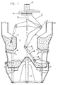
- FIG. 1 is a cross-section of an implement 1 for automatically detaching and displacing an amount of feed.
- the implement 1 is provided with a robot arm 2 with a detaching member 3 which is suitable for detaching feed from containers 4 that are integrated in a feeding column 5.
- the feeding column 5 comprises feeding and/or watering troughs 7 that are disposed around a central axis 6 and from which animals, such as cows for example, can eat and/or drink.
- Each of the feeding troughs 7 is capable of being closed separately by means of a closing member 8 which is constituted by a lid in the present embodiment.
- Under each of the feeding troughs 7 there is disposed a load cell 9 with the aid of which the weight of a relevant feeding trough can be determined.
- the robot arm is arranged centrally above the containers 4. This measure has the advantage that the robot arm 2 with the detaching member 4 can reach in a simple manner all the containers 4, as well as the feeding troughs 7.
- the robot arm 2 is also provided with a weighing device 10 which is designed as a load cell in the present embodiment. By means of the weighing device 10 it is possible to determine each time how much feed is taken from a container 4 and deposited in a particular feeding trough 7.
- the robot arm 2 is further provided with a first stepper motor 11 with the aid of which the robot arm 2 can be rotated about a vertical axis 12.
- the robot arm 2 is further provided with two further stepper motors 13 with the aid of which the robot arm can be positioned in the vertical plane.
- the end of the robot arm 2 comprises a telescopic cylinder 14.
- the detaching member 3 is designed as a gripper 15 with the aid of which feed can be seized and be released.
- an animal identification system 16 which makes it possible to recognize an animal that is standing near one of the troughs 7.
- the animal identification system 16 and a (non-shown) computer it can thus be determined whether or not an animal that is waiting near a feeding trough 7 will be fed.
- the gripper is particularly appropriate when roughage, such as for example silage or hay, has to be taken from a container 4.
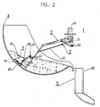
- Figure 2 shows a second embodiment of an implement 1 for automatically detaching and displacing an amount of feed from a container 4 of a (not completely depicted) feeding column 5.
- the robot arm 2 is differently designed than the robot arm 2 according to Figure 1.
- corresponding parts are indicated by the same reference numerals.
- the robot arm 2 comprises a quadrangular pivot construction 17.
- the detaching member 3 comprises a bucket 18 which is disposed at the end of the robot arm 2.
- the closing mechanism 19 comprises a closing lid 20 which is connected by means of a steering rod 21 to a stepper motor 22 which, after having been energized, causes the bucket 18 to be closed or opened.
- the closing mechanism 19 is further coupled with cleaning means 23 that are moved along the bottom and/or along the walls of the bucket 18 during opening and/or closing of said bucket 18.
- the cleaning means 23 comprise a brushing element 24.
- FIG 3 is a plan view of a stable 26 with a third embodiment of an implement 1 according to the invention arranged therein.
- the stable 26 comprises two rows of feed stands/cubicles 27 and at the end thereof two storage areas 28 for storing roughage and/or concentrate.
- the storage areas 28 each comprise a plurality of containers 4 for storing various sorts of fodder and/or drink. Between the two rows of feed stands 27 and the storage areas 28 there is disposed a rail 29 along which a transport vehicle 30 can be moved automatically under computer-control.
- a transport vehicle 30 can be moved automatically under computer-control.
- the robot arm 2 of the implement 1 in Figure 1 may be designed as the robot arm in Figure 1 or Figure 2.
- the robot arm 2 is also automatically movable under computer-control along the rail 29. With the aid of (non-shown) animal identification means it is thus possible to convey feed to a predetermined feed stand both by means of the robot arm 2 and the transport vehicle 30. It will be obvious that it is also possible to arrange a stationary robot arm 2 between the storage areas 28 and to convey the feed to a particular place only by means of the transport vehicle 30.
Landscapes
- Life Sciences & Earth Sciences (AREA)
- Environmental Sciences (AREA)
- Birds (AREA)
- Animal Husbandry (AREA)
- Biodiversity & Conservation Biology (AREA)
- Feeding And Watering For Cattle Raising And Animal Husbandry (AREA)
- Specific Conveyance Elements (AREA)
- Apparatuses For Bulk Treatment Of Fruits And Vegetables And Apparatuses For Preparing Feeds (AREA)
- Threshing Machine Elements (AREA)
- Refuse Collection And Transfer (AREA)
- Bridges Or Land Bridges (AREA)
Abstract
Description
Claims (21)
- An implement for automatically detaching and displacing an amount of feed, such as for example silage or hay, from a stock of feed, said implement (1) being provided with a robot arm (2) with a detaching member (3) which is suitable for detaching a part of the feed from the stock and displacing it to a predetermined place and depositing it there.
- An implement as claimed in claim 1, characterized in that the detaching member (3) comprises a gripping element (15).
- An implement as claimed in claim 1 or 2, characterized in that the detaching member (3) comprises a bucket (18) or a shovel.
- An implement as claimed in any one of the preceding claims, characterized in that the detaching member (3) is capable of being closed.
- An implement as claimed in any one of the preceding claims, characterized in that the robot arm (2) is provided with cleaning and/or brushing means (23, 24) for the detaching member (3).
- An implement as claimed in claim 5, characterized in that the cleaning and/or brushing means (23, 24) comprise a sweeping element (24).
- An implement as claimed in any one of the preceding claims, characterized in that the implement comprises metering means (9; 10) with the aid of which a predetermined measured out portion of feed can be detached.
- An implement as claimed in any one of the preceding claims, characterized in that the implement comprises weighing means (9; 10) for weighing said portion of feed.
- An implement as claimed in claim 8, characterized in that the robot arm (2) comprises the weighing means (9; 10).
- An implement as claimed in any one of the preceding claims, characterized in that the implement comprises animal identification means (16) with the aid of which an animal can be identified.
- An implement as claimed in claim 10, characterized in that the animal identification means (16) are fitted on the robot arm (2).
- An implement as claimed in any one of the preceding claims, characterized in that the implement comprises at least one feeding and/or watering trough (7).
- An implement as claimed in any one of the preceding claims, characterized in that the implement comprises at least one container (4) for storing the fodder and/or drink.
- An implement as claimed in claim 12 or 13, characterized in that the robot arm (2) is disposed above the feeding and/or watering trough (7) and/or above the container (4).
- An implement as claimed in any one of claims 12 to 14, characterized in that the implement is provided with a chute (25) via which the feed can be discharged to a relevant feeding and/or watering trough (7).
- An implement as claimed in any one of the preceding claims, characterized in that the robot arm (2) has such dimensions that the detaching member (13) can move over and/or along the bottom of the container (4) and/or the feeding and/or watering trough (7).
- An implement as claimed in any one of the preceding claims, characterized in that that at least the robot arm (2) is movable over a floor.
- An implement as claimed in claim 17, characterized in that the robot arm (2) is movable along a rail (29).
- An implement as claimed in any one of claims 1 to 16, characterized in that the implement comprises one or more transport vehicles (30) that co-operate with the robot arm (2).
- An implement as claimed in claim 18, characterized in that the transport vehicles (30) are movable along a rail (29).
- A feeding column provided with various feeding and/or watering troughs in which an implement as described in one or more of claims 1 to 19 can be applied.
Applications Claiming Priority (2)
| Application Number | Priority Date | Filing Date | Title |
|---|---|---|---|
| NL1015403 | 2000-06-09 | ||
| NL1015403A NL1015403C2 (en) | 2000-06-09 | 2000-06-09 | Device for automatically removing and moving a quantity of feed, such as, for example, silage grass or hay. |
Publications (3)
| Publication Number | Publication Date |
|---|---|
| EP1161861A2 true EP1161861A2 (en) | 2001-12-12 |
| EP1161861A3 EP1161861A3 (en) | 2002-04-10 |
| EP1161861B1 EP1161861B1 (en) | 2003-12-10 |
Family
ID=19771516
Family Applications (1)
| Application Number | Title | Priority Date | Filing Date |
|---|---|---|---|
| EP01201295A Expired - Lifetime EP1161861B1 (en) | 2000-06-09 | 2001-04-09 | An implement for automatically detaching and displacing an amount of feed, such as for example silage or hay |
Country Status (7)
| Country | Link |
|---|---|
| US (1) | US7614364B2 (en) |
| EP (1) | EP1161861B1 (en) |
| JP (1) | JP2002017194A (en) |
| AT (1) | ATE255808T1 (en) |
| DE (1) | DE60101419T2 (en) |
| DK (1) | DK1161861T3 (en) |
| NL (1) | NL1015403C2 (en) |
Cited By (4)
| Publication number | Priority date | Publication date | Assignee | Title |
|---|---|---|---|---|
| NL1019090C2 (en) * | 2001-10-03 | 2003-04-07 | Lely Entpr Ag | Device and method for automatically supplying at least two types of feed to animals. |
| NL1025616C2 (en) | 2004-03-02 | 2005-09-05 | Lely Entpr Ag | Transport device for bulk material and feed device with such a transport device. |
| NL1030090C2 (en) * | 2005-10-03 | 2007-04-04 | Maasland Nv | Assembly of a milking robot with a milking robot feeding place, such as a milking robot crib, and a device for gripping and moving material, such as for example roughage and / or concentrate for animals. |
| EP2191714A1 (en) | 2008-11-26 | 2010-06-02 | Lely Patent N.V. | Feed displacement device and an assembly therewith |
Families Citing this family (2)
| Publication number | Priority date | Publication date | Assignee | Title |
|---|---|---|---|---|
| US8641374B2 (en) * | 2010-06-30 | 2014-02-04 | Vestas Wind Systems A/S | Cleaning and inspecting apparatus for wind turbine and related methods |
| DE102011000098B3 (en) | 2011-01-11 | 2012-05-16 | Förster Technik GmbH | Method and device for supplying, controlling and / or monitoring animals |
Family Cites Families (19)
| Publication number | Priority date | Publication date | Assignee | Title |
|---|---|---|---|---|
| US1333387A (en) * | 1919-08-15 | 1920-03-09 | George C Cato | Scoop |
| US3804448A (en) * | 1972-04-28 | 1974-04-16 | W Schmieler | Sanitary scavenging implement |
| US4180136A (en) * | 1978-09-15 | 1979-12-25 | Intraco, Inc | Weight actuated feed drop apparatus |
| US4337729A (en) * | 1980-05-13 | 1982-07-06 | Chore-Time Equipment, Inc. | Traveling hopper feed delivery system |
| NZ206612A (en) * | 1982-12-21 | 1986-10-08 | T S Wilman | Mechanical grab and scoop combination |
| US4672917A (en) * | 1985-02-26 | 1987-06-16 | Fox Harvey Z | Feeder |
| DE3510401A1 (en) * | 1985-03-22 | 1986-09-25 | Klaus-Peter 4518 Bad Laer Strautmann | Silo-bale distributor |
| US4949675A (en) * | 1988-12-13 | 1990-08-21 | Parks Jack C | Automatic animal feeder |
| US4981107A (en) * | 1989-03-31 | 1991-01-01 | Micro-Contact Inc. | Computerized automatic cattle-feeder system |
| DE3921871A1 (en) * | 1989-07-04 | 1991-01-17 | Anton Niederberger | Automatic animal fodder dispensing system - has pivoted gripper device at end of telescopic rod transported to each feeding point |
| GB2239960B (en) * | 1989-12-07 | 1993-09-08 | Michael John Topping | Eating apparatus |
| US5069165A (en) * | 1990-10-12 | 1991-12-03 | Victor Rousseau | Livestock feeder system |
| NL9401801A (en) * | 1994-08-23 | 1996-04-01 | Maasland Nv | Construction with a device for milking animals. |
| NL9401876A (en) * | 1994-11-10 | 1996-06-03 | Maasland Nv | Feed trolley. |
| JP3773529B2 (en) * | 1994-12-28 | 2006-05-10 | デラヴァール ホルディング アクチボラゲット | Livestock management apparatus and management method |
| EP0721732B2 (en) * | 1995-01-11 | 2010-11-10 | Maasland N.V. | A construction for displacing feed for animals |
| NL1002487C2 (en) * | 1996-02-29 | 1997-09-01 | Maasland Nv | Construction with animal housing equipment. |
| NL1010898C2 (en) * | 1998-12-24 | 2000-06-27 | Lely Research Holding Ag | Feeding column and / or drinking column for feeding animals. |
| US6481373B2 (en) * | 1999-12-29 | 2002-11-19 | Swetzig Deanna K. | Programmable hay-forage feeder |
-
2000
- 2000-06-09 NL NL1015403A patent/NL1015403C2/en not_active IP Right Cessation
-
2001
- 2001-04-09 AT AT01201295T patent/ATE255808T1/en not_active IP Right Cessation
- 2001-04-09 DK DK01201295T patent/DK1161861T3/en active
- 2001-04-09 DE DE60101419T patent/DE60101419T2/en not_active Expired - Lifetime
- 2001-04-09 EP EP01201295A patent/EP1161861B1/en not_active Expired - Lifetime
- 2001-05-16 US US09/855,535 patent/US7614364B2/en not_active Expired - Fee Related
- 2001-05-21 JP JP2001150672A patent/JP2002017194A/en not_active Withdrawn
Cited By (6)
| Publication number | Priority date | Publication date | Assignee | Title |
|---|---|---|---|---|
| NL1019090C2 (en) * | 2001-10-03 | 2003-04-07 | Lely Entpr Ag | Device and method for automatically supplying at least two types of feed to animals. |
| NL1025616C2 (en) | 2004-03-02 | 2005-09-05 | Lely Entpr Ag | Transport device for bulk material and feed device with such a transport device. |
| EP1570730A1 (en) | 2004-03-02 | 2005-09-07 | Lely Enterprises AG | A transport installation for bulk material and a feeding installation provided with such a transport installation |
| NL1030090C2 (en) * | 2005-10-03 | 2007-04-04 | Maasland Nv | Assembly of a milking robot with a milking robot feeding place, such as a milking robot crib, and a device for gripping and moving material, such as for example roughage and / or concentrate for animals. |
| WO2007040388A1 (en) * | 2005-10-03 | 2007-04-12 | Maasland N.V. | An assembly of a milking robot with a milking robot feeding place, such as a milking robot feed trough, and a device for gripping and displacing material, such as for example roughage and/or concentrate for animals |
| EP2191714A1 (en) | 2008-11-26 | 2010-06-02 | Lely Patent N.V. | Feed displacement device and an assembly therewith |
Also Published As
| Publication number | Publication date |
|---|---|
| US7614364B2 (en) | 2009-11-10 |
| US20010051084A1 (en) | 2001-12-13 |
| DE60101419T2 (en) | 2004-10-07 |
| DK1161861T3 (en) | 2004-04-05 |
| EP1161861A3 (en) | 2002-04-10 |
| ATE255808T1 (en) | 2003-12-15 |
| JP2002017194A (en) | 2002-01-22 |
| EP1161861B1 (en) | 2003-12-10 |
| NL1015403C2 (en) | 2002-01-04 |
| DE60101419D1 (en) | 2004-01-22 |
Similar Documents
| Publication | Publication Date | Title |
|---|---|---|
| US6263833B1 (en) | Livestock feed dispenser | |
| US20080251024A1 (en) | Assembly of Milking a Robot With a Milking Robot Feeding Place, Such as a Milking Robot Feed Trough, and a Device For Gripping and Displacing Material, Such as For Example Roughage and/or Concentrate For Animals | |
| EP1161861B1 (en) | An implement for automatically detaching and displacing an amount of feed, such as for example silage or hay | |
| KR102609255B1 (en) | Feed conveying and feeding device for flow conveyors | |
| US6481373B2 (en) | Programmable hay-forage feeder | |
| NL2014096A (en) | Feeding system and method for feeding non-human animals. | |
| KR20190016839A (en) | Animal feeder | |
| EP1516848A1 (en) | A device for gripping and displacing material, such as roughage for example | |
| EP0721732B2 (en) | A construction for displacing feed for animals | |
| EP1230847A2 (en) | A device for supplying fodder to animals | |
| DE102006053194A1 (en) | Liquid and/or solid form food providing mechanism for animal, has holder attached to vehicle that is movable automatically and driven in independent manner, where vehicle is provided with independent drive i.e. electric drive | |
| CN212374160U (en) | A feed warehouse storage and reclaiming device | |
| EP1300071B1 (en) | A device for supplying feed to animals | |
| US12082562B2 (en) | Feeding system and method for feeding animals, and feed grabber | |
| NL1025616C2 (en) | Transport device for bulk material and feed device with such a transport device. | |
| EP0721733B1 (en) | A construction for displacing feed | |
| WO2010094066A1 (en) | Spreader mechanism with two elongate spreader members having projections | |
| DE8809776U1 (en) | Device for feeding animals | |
| AU630682B2 (en) | Feed system | |
| AU597895B2 (en) | Stock feeder | |
| SU648176A1 (en) | Unit for housing animal | |
| CA1144102A (en) | Hydraulic drill fill | |
| CN113331072A (en) | Dry powder feed metering feeding and separating device | |
| SK242391A3 (en) | Device for registered feed distribution |
Legal Events
| Date | Code | Title | Description |
|---|---|---|---|
| PUAI | Public reference made under article 153(3) epc to a published international application that has entered the european phase |
Free format text: ORIGINAL CODE: 0009012 |
|
| AK | Designated contracting states |
Kind code of ref document: A2 Designated state(s): AT BE CH CY DE DK ES FI FR GB GR IE IT LI LU MC NL PT SE TR |
|
| AX | Request for extension of the european patent |
Free format text: AL;LT;LV;MK;RO;SI |
|
| PUAL | Search report despatched |
Free format text: ORIGINAL CODE: 0009013 |
|
| AK | Designated contracting states |
Kind code of ref document: A3 Designated state(s): AT BE CH CY DE DK ES FI FR GB GR IE IT LI LU MC NL PT SE TR |
|
| AX | Request for extension of the european patent |
Free format text: AL;LT;LV;MK;RO;SI |
|
| 17P | Request for examination filed |
Effective date: 20020821 |
|
| 17Q | First examination report despatched |
Effective date: 20021007 |
|
| AKX | Designation fees paid |
Free format text: AT BE CH CY DE DK ES FI FR GB GR IE IT LI LU MC NL PT SE TR |
|
| GRAH | Despatch of communication of intention to grant a patent |
Free format text: ORIGINAL CODE: EPIDOS IGRA |
|
| GRAS | Grant fee paid |
Free format text: ORIGINAL CODE: EPIDOSNIGR3 |
|
| GRAA | (expected) grant |
Free format text: ORIGINAL CODE: 0009210 |
|
| AK | Designated contracting states |
Kind code of ref document: B1 Designated state(s): AT BE CH CY DE DK ES FI FR GB GR IE IT LI LU MC NL PT SE TR |
|
| PG25 | Lapsed in a contracting state [announced via postgrant information from national office to epo] |
Ref country code: LI Free format text: LAPSE BECAUSE OF FAILURE TO SUBMIT A TRANSLATION OF THE DESCRIPTION OR TO PAY THE FEE WITHIN THE PRESCRIBED TIME-LIMIT Effective date: 20031210 Ref country code: CY Free format text: LAPSE BECAUSE OF FAILURE TO SUBMIT A TRANSLATION OF THE DESCRIPTION OR TO PAY THE FEE WITHIN THE PRESCRIBED TIME-LIMIT Effective date: 20031210 Ref country code: IT Free format text: LAPSE BECAUSE OF FAILURE TO SUBMIT A TRANSLATION OF THE DESCRIPTION OR TO PAY THE FEE WITHIN THE PRESCRIBED TIME-LIMIT;WARNING: LAPSES OF ITALIAN PATENTS WITH EFFECTIVE DATE BEFORE 2007 MAY HAVE OCCURRED AT ANY TIME BEFORE 2007. THE CORRECT EFFECTIVE DATE MAY BE DIFFERENT FROM THE ONE RECORDED. Effective date: 20031210 Ref country code: AT Free format text: LAPSE BECAUSE OF FAILURE TO SUBMIT A TRANSLATION OF THE DESCRIPTION OR TO PAY THE FEE WITHIN THE PRESCRIBED TIME-LIMIT Effective date: 20031210 Ref country code: BE Free format text: LAPSE BECAUSE OF FAILURE TO SUBMIT A TRANSLATION OF THE DESCRIPTION OR TO PAY THE FEE WITHIN THE PRESCRIBED TIME-LIMIT Effective date: 20031210 Ref country code: TR Free format text: LAPSE BECAUSE OF FAILURE TO SUBMIT A TRANSLATION OF THE DESCRIPTION OR TO PAY THE FEE WITHIN THE PRESCRIBED TIME-LIMIT Effective date: 20031210 Ref country code: FI Free format text: LAPSE BECAUSE OF FAILURE TO SUBMIT A TRANSLATION OF THE DESCRIPTION OR TO PAY THE FEE WITHIN THE PRESCRIBED TIME-LIMIT Effective date: 20031210 Ref country code: ES Free format text: LAPSE BECAUSE OF FAILURE TO SUBMIT A TRANSLATION OF THE DESCRIPTION OR TO PAY THE FEE WITHIN THE PRESCRIBED TIME-LIMIT Effective date: 20031210 Ref country code: CH Free format text: LAPSE BECAUSE OF FAILURE TO SUBMIT A TRANSLATION OF THE DESCRIPTION OR TO PAY THE FEE WITHIN THE PRESCRIBED TIME-LIMIT Effective date: 20031210 |
|
| REG | Reference to a national code |
Ref country code: GB Ref legal event code: FG4D |
|
| REG | Reference to a national code |
Ref country code: CH Ref legal event code: EP |
|
| REG | Reference to a national code |
Ref country code: IE Ref legal event code: FG4D |
|
| REF | Corresponds to: |
Ref document number: 60101419 Country of ref document: DE Date of ref document: 20040122 Kind code of ref document: P |
|
| PG25 | Lapsed in a contracting state [announced via postgrant information from national office to epo] |
Ref country code: GR Free format text: LAPSE BECAUSE OF FAILURE TO SUBMIT A TRANSLATION OF THE DESCRIPTION OR TO PAY THE FEE WITHIN THE PRESCRIBED TIME-LIMIT Effective date: 20040310 Ref country code: SE Free format text: LAPSE BECAUSE OF FAILURE TO SUBMIT A TRANSLATION OF THE DESCRIPTION OR TO PAY THE FEE WITHIN THE PRESCRIBED TIME-LIMIT Effective date: 20040310 |
|
| REG | Reference to a national code |
Ref country code: DK Ref legal event code: T3 |
|
| PG25 | Lapsed in a contracting state [announced via postgrant information from national office to epo] |
Ref country code: LU Free format text: LAPSE BECAUSE OF NON-PAYMENT OF DUE FEES Effective date: 20040409 Ref country code: IE Free format text: LAPSE BECAUSE OF NON-PAYMENT OF DUE FEES Effective date: 20040409 |
|
| PG25 | Lapsed in a contracting state [announced via postgrant information from national office to epo] |
Ref country code: MC Free format text: LAPSE BECAUSE OF NON-PAYMENT OF DUE FEES Effective date: 20040430 |
|
| REG | Reference to a national code |
Ref country code: CH Ref legal event code: PL |
|
| ET | Fr: translation filed | ||
| PLBE | No opposition filed within time limit |
Free format text: ORIGINAL CODE: 0009261 |
|
| STAA | Information on the status of an ep patent application or granted ep patent |
Free format text: STATUS: NO OPPOSITION FILED WITHIN TIME LIMIT |
|
| 26N | No opposition filed |
Effective date: 20040913 |
|
| REG | Reference to a national code |
Ref country code: IE Ref legal event code: MM4A |
|
| PG25 | Lapsed in a contracting state [announced via postgrant information from national office to epo] |
Ref country code: GB Free format text: LAPSE BECAUSE OF NON-PAYMENT OF DUE FEES Effective date: 20050409 |
|
| GBPC | Gb: european patent ceased through non-payment of renewal fee |
Effective date: 20050409 |
|
| PG25 | Lapsed in a contracting state [announced via postgrant information from national office to epo] |
Ref country code: PT Free format text: LAPSE BECAUSE OF NON-PAYMENT OF DUE FEES Effective date: 20040510 |
|
| PGFP | Annual fee paid to national office [announced via postgrant information from national office to epo] |
Ref country code: DE Payment date: 20130429 Year of fee payment: 13 Ref country code: DK Payment date: 20130429 Year of fee payment: 13 |
|
| PGFP | Annual fee paid to national office [announced via postgrant information from national office to epo] |
Ref country code: FR Payment date: 20140417 Year of fee payment: 14 Ref country code: NL Payment date: 20140426 Year of fee payment: 14 |
|
| REG | Reference to a national code |
Ref country code: DE Ref legal event code: R119 Ref document number: 60101419 Country of ref document: DE |
|
| REG | Reference to a national code |
Ref country code: DK Ref legal event code: EBP Effective date: 20140430 |
|
| REG | Reference to a national code |
Ref country code: DE Ref legal event code: R119 Ref document number: 60101419 Country of ref document: DE Effective date: 20141101 |
|
| PG25 | Lapsed in a contracting state [announced via postgrant information from national office to epo] |
Ref country code: DE Free format text: LAPSE BECAUSE OF NON-PAYMENT OF DUE FEES Effective date: 20141101 |
|
| PG25 | Lapsed in a contracting state [announced via postgrant information from national office to epo] |
Ref country code: DK Free format text: LAPSE BECAUSE OF NON-PAYMENT OF DUE FEES Effective date: 20140430 |
|
| REG | Reference to a national code |
Ref country code: NL Ref legal event code: MM Effective date: 20150501 |
|
| REG | Reference to a national code |
Ref country code: FR Ref legal event code: ST Effective date: 20151231 |
|
| PG25 | Lapsed in a contracting state [announced via postgrant information from national office to epo] |
Ref country code: FR Free format text: LAPSE BECAUSE OF NON-PAYMENT OF DUE FEES Effective date: 20150430 |
|
| PG25 | Lapsed in a contracting state [announced via postgrant information from national office to epo] |
Ref country code: NL Free format text: LAPSE BECAUSE OF NON-PAYMENT OF DUE FEES Effective date: 20150501 |