EP1160800A1 - Anordnung zum funktionserhalt eines Kabels im Brandfall - Google Patents
Anordnung zum funktionserhalt eines Kabels im Brandfall Download PDFInfo
- Publication number
- EP1160800A1 EP1160800A1 EP00401411A EP00401411A EP1160800A1 EP 1160800 A1 EP1160800 A1 EP 1160800A1 EP 00401411 A EP00401411 A EP 00401411A EP 00401411 A EP00401411 A EP 00401411A EP 1160800 A1 EP1160800 A1 EP 1160800A1
- Authority
- EP
- European Patent Office
- Prior art keywords
- cable
- function
- fire
- casing
- arrangement according
- Prior art date
- Legal status (The legal status is an assumption and is not a legal conclusion. Google has not performed a legal analysis and makes no representation as to the accuracy of the status listed.)
- Withdrawn
Links
- 239000004020 conductor Substances 0.000 claims abstract description 15
- 239000000463 material Substances 0.000 claims abstract description 13
- 229910052500 inorganic mineral Inorganic materials 0.000 claims abstract description 7
- 239000011707 mineral Substances 0.000 claims abstract description 7
- 239000011810 insulating material Substances 0.000 claims abstract description 6
- 239000004033 plastic Substances 0.000 claims description 4
- 239000002184 metal Substances 0.000 claims description 3
- 239000011490 mineral wool Substances 0.000 claims description 3
- 230000008054 signal transmission Effects 0.000 claims description 3
- RNFJDJUURJAICM-UHFFFAOYSA-N 2,2,4,4,6,6-hexaphenoxy-1,3,5-triaza-2$l^{5},4$l^{5},6$l^{5}-triphosphacyclohexa-1,3,5-triene Chemical compound N=1P(OC=2C=CC=CC=2)(OC=2C=CC=CC=2)=NP(OC=2C=CC=CC=2)(OC=2C=CC=CC=2)=NP=1(OC=1C=CC=CC=1)OC1=CC=CC=C1 RNFJDJUURJAICM-UHFFFAOYSA-N 0.000 claims description 2
- 239000003063 flame retardant Substances 0.000 claims description 2
- 230000005540 biological transmission Effects 0.000 description 3
- 239000000853 adhesive Substances 0.000 description 2
- 230000001070 adhesive effect Effects 0.000 description 2
- 230000004888 barrier function Effects 0.000 description 2
- 238000004891 communication Methods 0.000 description 2
- 239000011521 glass Substances 0.000 description 2
- 239000010445 mica Substances 0.000 description 2
- 229910052618 mica group Inorganic materials 0.000 description 2
- 230000001681 protective effect Effects 0.000 description 2
- 239000004642 Polyimide Substances 0.000 description 1
- 239000010425 asbestos Substances 0.000 description 1
- 238000005516 engineering process Methods 0.000 description 1
- 230000009970 fire resistant effect Effects 0.000 description 1
- 238000012423 maintenance Methods 0.000 description 1
- 230000003287 optical effect Effects 0.000 description 1
- 229920001721 polyimide Polymers 0.000 description 1
- 230000005855 radiation Effects 0.000 description 1
- 229910052895 riebeckite Inorganic materials 0.000 description 1
Images
Classifications
-
- G—PHYSICS
- G02—OPTICS
- G02B—OPTICAL ELEMENTS, SYSTEMS OR APPARATUS
- G02B6/00—Light guides; Structural details of arrangements comprising light guides and other optical elements, e.g. couplings
- G02B6/44—Mechanical structures for providing tensile strength and external protection for fibres, e.g. optical transmission cables
- G02B6/4401—Optical cables
- G02B6/4429—Means specially adapted for strengthening or protecting the cables
- G02B6/4436—Heat resistant
-
- H—ELECTRICITY
- H01—ELECTRIC ELEMENTS
- H01B—CABLES; CONDUCTORS; INSULATORS; SELECTION OF MATERIALS FOR THEIR CONDUCTIVE, INSULATING OR DIELECTRIC PROPERTIES
- H01B7/00—Insulated conductors or cables characterised by their form
- H01B7/17—Protection against damage caused by external factors, e.g. sheaths or armouring
- H01B7/29—Protection against damage caused by extremes of temperature or by flame
- H01B7/295—Protection against damage caused by extremes of temperature or by flame using material resistant to flame
Definitions
- the invention relates to an arrangement for maintaining the function of a cable in Fire event which has conductors serving for the transmission of signals by a common sheath of insulating material are surrounded, and in which one Functional maintenance of the cable, the layer surrounding the conductor is present (EP 0 308 111 B1).
- Such cables can be communication cables with electrical and / or optical conductors as well as high-frequency cables (RF cables), such as coaxial RF cables, radiating RF cables and waveguide. All of these cables are used for the transmission of communications or high-frequency signals.
- RF cables high-frequency cables
- Receiving her Functionality is in most applications - especially in the case of one Fire with an open flame - essential. It must then be ensured be that the respective cable its function at least for a predetermined period of time maintains.
- Corresponding requirements are, for example, the international regulation To be taken from IEC 60331.
- an electrical line with a special jacket is based an insulating material that maintains the function of the line even when open Flame with temperatures up to 540 ° C.
- the coat has one Barrier layer consisting of mica applied to a glass support or asbestos.
- a polyimide cover is attached over the barrier layer is in turn surrounded by a protective jacket.
- EP 0 308 11 B1 mentioned at the beginning describes a radiating coaxial HF cable with holes in the tubular outer conductor.
- a protective jacket made of flame-resistant material is also attached to the tape.
- the Band consists of mica impregnated with a heat-resistant adhesive a carrier made of glass threads is attached. The effort to protect this RF cable against high temperatures is significant, as with other known cables.
- the invention has for its object to the arrangement described above design that the function of the cable in the event of fire even at temperatures of more than 1000 ° C can be easily achieved.
- This object is achieved according to this invention in that on the jacket the entire length of the cable is a completely closed sheath from one flammable, mineral material is attached.
- any conventional cable is easily against high Temperatures protected as they occur in the event of a fire with an open flame.
- the whole essential advantage of the arrangement is that the respective cable in the usual Technology with materials that are tailored to its intended use can. Additional layers or layers of a special, temperature-resistant Material is not required.
- the cable itself is finished with this arrangement finally embedded in the shell made of non-combustible, mineral material. In the event of a fire, its function is guaranteed for a long time.
- the cover is expediently made of a thin, surrounding moisture-proof layer.
- This can consist of metal.
- the layer consists of Plastic.
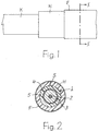
- any cable K is shown for the transmission of signals. It is executed in the illustrated embodiment as a coaxial RF cable 1, the one Inner conductor 2, a dielectric 3 surrounding the same and one to the inner conductor 2 Has concentric, tubular outer conductor 4. Over the outer conductor 4 is a Jacket 5 made of insulating material attached.
- the HF cable 1 can only be used to comply with optimal transmission properties. Special measures for Protection against fire need not be provided.
- the cable K is in its entire length in a completely closed sheath H from one non-flammable, mineral material embedded.
- material is for example mineral wool, such as the rock wool commercially available.
- the envelope H protects the cable K in the event of fire in front of open flames so that it cannot burn. It can thereby maintaining its function at least for a sufficient time until possibly a short circuit between due to softening of the insulating material electrical conductors.
- Layer F can be made of metal or plastic consist. It is thin in relation to the radial height (thickness) of the envelope H. If that Cable K is a radiating RF cable, then sheath H and layer F consist metal-free material that does not interfere with the radiation properties. For the layer F is then preferably used a flame-retardant plastic, the one Prevents the transmission of flames and deprives them of additional energy.
- the shell H consists of prefabricated, on one Longitudinal slot S open pipes. Such pipes can be easily connected to the cable K be plugged on.
- the longitudinal slot S becomes the passage of the cable K expanded. He goes back through some restoring force and can complete the Cover H be closed with a fire-resistant adhesive.
Landscapes
- Physics & Mathematics (AREA)
- General Physics & Mathematics (AREA)
- Optics & Photonics (AREA)
- Insulated Conductors (AREA)
Abstract
Es wird eine Anordnung zum Funktionserhalt eines Kabels (1) im Brandfall angegeben, das der Übertragung von Signalen dienende Leiter (2,4) aufweist, die von einem gemeinsamen Mantel (5) aus Isoliermaterial umgeben sind. Es ist außerdem eine den Funktionserhalt des Kabels (1) sichernde, die Leiter (2,4) umgebende Schicht vorhanden. Als funktionserhaltende Schicht ist über dem Mantel (5) auf der ganzen Länge des Kabels (1) eine rundum geschlossene Hülle (H) aus einem nicht brennbaren, mineralischen Material angebracht. <IMAGE>
Description
Die Erfindung bezieht sich auf eine Anordnung zum Funktionserhalt eines Kabels im
Brandfall, das der Übertragung von Signalen dienende Leiter aufweist, die von einem
gemeinsamen Mantel aus Isoliermaterial umgeben sind, und bei welchem eine den
Funktionserhalt des Kabels sichernde, die Leiter umgebende Schicht vorhanden ist
(EP 0 308 111 B1).
Derartige Kabel können Nachrichtenkabel mit elektrischen und/oder optischen Leitern
sowie Hochfrequenzkabel (HF-Kabel) sein, wie koaxiale HF-Kabel, abstrahlende HF-Kabel
und Hohlleiter. Alle diese Kabel dienen der Übertragung von
nachrichtentechnischen bzw. hochfrequenten Signalen. Der Erhalt ihrer
Funktionsfähigkeit ist in den meisten Einsatzfällen - insbesondere auch im Falle eines
Brandes mit offener Flamme - von wesentlicher Bedeutung. Es muß dann sichergestellt
sein, daß das jeweilige Kabel seine Funktion zumindest für eine vorgegebene Zeitdauer
beibehält. Entsprechende Forderungen sind beispielsweise der internationalen Vorschrift
IEC 60331 zu entnehmen.
Aus der US-PS 3,425,865 geht eine elektrische Leitung mit einem speziellen Mantel aus
einem Isoliermaterial hervor, das einen Funktionserhalt der Leitung auch bei offener
Flamme mit Temperaturen bis zu 540 °C sicherstellen soll. Der Mantel weist eine
Barriereschicht auf, die aus auf einen Träger aus Glas aufgebrachtem Glimmer (Mica)
oder Asbest besteht. Über der Barriereschicht ist eine Polyimidumhüllung angebracht, die
ihrerseits von einem Schutzmantel umgeben ist.
Die eingangs erwähnte EP 0 308 11 B1 beschreibt ein abstrahlendes koaxiales HF-Kabel
mit Löchern im rohrförmigen Außenleiter. Über dem Außenleiter ist mindestens ein Band
aus einem Material angebracht, das Temperaturen bis zu 1000 °C aushält. Über dem
Band ist zusätzlich ein Schutzmantel aus flammbeständigem Material angebracht. Das
Band besteht aus mit einem hitzebeständigen Kleber imprägnierten Glimmer, der auf
einem Träger aus Glasfäden angebracht ist. Der Aufwand zum Schutz dieses HF-Kabels
gegen hohe Temperaturen ist ebenso wie bei anderen bekannten Kabeln erheblich.
Der Erfindung liegt die Aufgabe zugrunde, die eingangs geschilderte Anordnung so zu
gestalten, daß ein Funktionserhalt des Kabels im Brandfall auch bei Temperaturen von
mehr als 1000°C auf einfache Weise erreicht werden kann.
Diese Aufgabe wird gemäß dieser Erfindung dadurch gelöst, daß über dem Mantel auf
der ganzen Länge des Kabels eine rundum geschlossene Hülle aus einem nicht
brennbaren, mineralischen Material angebracht ist.
Mit dieser Anordnung ist jedes herkömmliche Kabel auf einfache Weise gegen hohe
Temperaturen geschützt, wie sie im Brandfall bei offener Flamme auftreten. Der ganz
wesentliche Vorteil der Anordnung besteht darin, daß das jeweilige Kabel in üblicher
Technik mit auf seinen Verwendungszweck abgestimmten Materialien aufgebaut werden
kann. Zusätzliche Schichten oder Schichten aus einem speziellen, temperaturbeständigen
Material sind nicht erforderlich. Das an sich fertige Kabel wird bei dieser Anordnung
abschließend in die Hülle aus nicht brennbarem, mineralischem Material eingebettet.
Sein Funktionserhalt ist dadurch im Brandfall für lange Zeit gesichert.
Zum Schutz gegen Feuchtigkeit ist die Hülle zweckmäßig von einer dünnen,
feuchtigkeitsdichten Schicht umgeben. Diese kann aus Metall bestehen. Beispielsweise
beim Einsatz der Anordnung für abstrahlende HF-Kabel besteht die Schicht aus
Kunststoff.
Weitere vorteilhafte Ausgestaltungen der Erfindung gehen aus den Unteransprüchen
hervor.
Ein Ausführungsbeispiel des Erfindungsgegenstandes ist in den Zeichnungen dargestellt.
In Fig. 1 ist ein beliebiges Kabel K zur Übertragung von Signalen wiedergegeben. Es ist
im dargestellten Ausführungsbeispiel als koaxiales HF-Kabel 1 ausgeführt, das einen
Innenleiter 2, ein denselben umgebendes Dielektrikum 3 und einen zum Innenleiter 2
konzentrischen, rohrförmigen Außenleiter 4 aufweist. Über dem Außenleiter 4 ist ein
Mantel 5 aus Isoliermaterial angebracht. Das HF-Kabel 1 kann nur zur Einhaltung von
optimalen Übertragungseigenschaften ausgelegt sein. Besondere Maßnahmen zum
Schutz gegen Feuer brauchen nicht vorgesehen zu sein.
Das Kabel K ist auf seiner ganzen Länge in eine rundum geschlossene Hülle H aus einem
nicht brennbaren, mineralischen Material eingebettet. Ein solches Material ist
beispielsweise Mineralwolle, wie die im Handel erhältliche Steinwolle. Die Hülle H schützt
das Kabel K im Brandfalle vor offenen Flammen, so daß es nicht brennen kann. Es kann
dadurch seine Funktion zumindest für eine ausreichende Zeit beibehalten, bis
möglicherweise durch Erweichung von Isoliermaterial ein Kurzschluß zwischen
elektrischen Leitern entsteht.
Um die Hülle H vor Feuchtigkeit zu schützen, ist über derselben eine feuchtigkeitsdichte
äußere Schicht F angebracht. Die Schicht F kann aus Metall oder aus Kunststoff
bestehen. Sie ist dünn im Verhältnis zur radialen Höhe (Dicke) der Hülle H. Wenn das
Kabel K ein abstrahlendes HF-Kabel ist, dann bestehen Hülle H und Schicht F aus
metallfreiem, die Abstrahlungseigenschaften nicht störend beeinflussendem Material. Für
die Schicht F wird dann vorzugsweise ein flammwidriger Kunststoff verwendet, der eine
Weiterleitung von Flammen verhindert und denselben zusätzlich Energie entzieht.
Die Hülle H besteht in bevorzugter Ausführungsform aus vorgefertigten, an einem
Längsschlitz S offenen Rohren. Solche Rohre können in einfacher Weise auf das Kabel K
aufgesteckt werden. Dabei wird der Längsschlitz S zum Durchlaß des Kabels K
aufgeweitet. Er geht durch einige Rückstellkraft wieder zu und kann zur Fertigstellung der
Hülle H mit einem feuerfesten Kleber verschlossen werden.
Claims (8)
- Anordnung zum Funktionserhalt eines Kabels im Brandfall, das der Übertragung von Signalen dienende Leiter aufweist, die von einem gemeinsamen Mantel aus Isoliermaterial umgeben sind, und bei welchem eine den Funktionserhalt des Kabels sichernde, die Leiter umgebende Schicht vorhanden ist, dadurch gekennzeichnet, daß über dem Mantel (5) auf der ganzen Länge des Kabels (K) eine rundum geschlossene Hülle (H) aus einem nicht brennbaren, mineralischen Material angebracht ist.
- Anordnung nach Anspruch 1, dadurch gekennzeichnet, daß die Hülle (H) aus Steinwolle besteht.
- Anordnung nach Anspruch 1 oder 2, dadurch gekennzeichnet, daß die Hülle (H) von einer feuchtigkeitsdichten äußeren Schicht (F) umgeben ist.
- Anordnung nach einem der Ansprüche 1 oder 3, dadurch gekennzeichnet, daß die äußere Schicht (F) dünn ist im Verhältnis zur radialen Höhe der Hülle (H).
- Anordnung nach einem der Ansprüche 1 bis 4, dadurch gekennzeichnet, daß die Schicht (F) aus Metall besteht.
- Anordnung nach einem der Ansprüche 1 bis 4, dadurch gekennzeichnet, daß die Schicht (F) aus flammwidrigem Kunststoff besteht.
- Verwendung der Hülle (H) aus nicht brennbarem, mineralischem Material für ein koaxiales Hochfrequenzkabel (1).
- Verwendung der Hülle (H) aus nicht brennbarem, mineralischem Material für ein abstrahlendes Hochfrequenzkabel.
Priority Applications (1)
| Application Number | Priority Date | Filing Date | Title |
|---|---|---|---|
| EP00401411A EP1160800A1 (de) | 2000-05-22 | 2000-05-22 | Anordnung zum funktionserhalt eines Kabels im Brandfall |
Applications Claiming Priority (1)
| Application Number | Priority Date | Filing Date | Title |
|---|---|---|---|
| EP00401411A EP1160800A1 (de) | 2000-05-22 | 2000-05-22 | Anordnung zum funktionserhalt eines Kabels im Brandfall |
Publications (1)
| Publication Number | Publication Date |
|---|---|
| EP1160800A1 true EP1160800A1 (de) | 2001-12-05 |
Family
ID=8173696
Family Applications (1)
| Application Number | Title | Priority Date | Filing Date |
|---|---|---|---|
| EP00401411A Withdrawn EP1160800A1 (de) | 2000-05-22 | 2000-05-22 | Anordnung zum funktionserhalt eines Kabels im Brandfall |
Country Status (1)
| Country | Link |
|---|---|
| EP (1) | EP1160800A1 (de) |
Citations (6)
| Publication number | Priority date | Publication date | Assignee | Title |
|---|---|---|---|---|
| GB2130785A (en) * | 1982-10-01 | 1984-06-06 | Delta Enfield Ltd | Fire-resistant electrical cable |
| US4510348A (en) * | 1983-03-28 | 1985-04-09 | At&T Technologies, Inc. | Non-shielded, fire-resistant plenum cable |
| EP0366473A2 (de) * | 1988-10-27 | 1990-05-02 | BICC Public Limited Company | Elektrische Kabel |
| EP0526081A1 (de) * | 1991-07-23 | 1993-02-03 | BICC Public Limited Company | Elektrische und Nachrichten-Kabel |
| US5227586A (en) * | 1991-10-07 | 1993-07-13 | Harbour Industries, (Canada) Ltd. | Flame resistant electric cable |
| US5705774A (en) * | 1995-11-24 | 1998-01-06 | Harbour Industries (Canada) Ltd. | Flame resistant electric cable |
-
2000
- 2000-05-22 EP EP00401411A patent/EP1160800A1/de not_active Withdrawn
Patent Citations (6)
| Publication number | Priority date | Publication date | Assignee | Title |
|---|---|---|---|---|
| GB2130785A (en) * | 1982-10-01 | 1984-06-06 | Delta Enfield Ltd | Fire-resistant electrical cable |
| US4510348A (en) * | 1983-03-28 | 1985-04-09 | At&T Technologies, Inc. | Non-shielded, fire-resistant plenum cable |
| EP0366473A2 (de) * | 1988-10-27 | 1990-05-02 | BICC Public Limited Company | Elektrische Kabel |
| EP0526081A1 (de) * | 1991-07-23 | 1993-02-03 | BICC Public Limited Company | Elektrische und Nachrichten-Kabel |
| US5227586A (en) * | 1991-10-07 | 1993-07-13 | Harbour Industries, (Canada) Ltd. | Flame resistant electric cable |
| US5705774A (en) * | 1995-11-24 | 1998-01-06 | Harbour Industries (Canada) Ltd. | Flame resistant electric cable |
Similar Documents
| Publication | Publication Date | Title |
|---|---|---|
| DE2033675C3 (de) | Biegsames elektrisches Kabel für die Signalübertragung | |
| DE3586290T2 (de) | Optisches kabel. | |
| EP1667169B1 (de) | Elektrisches Kabel | |
| EP1199728A2 (de) | Isolierter elektrischer Leiter mit Funktionserhalt im Brandfall | |
| EP0260373B1 (de) | Flammbeständige elektrische Leitung | |
| DE3444500C2 (de) | ||
| EP0899750A2 (de) | Koaxiales Hochfrequenz-Kabel | |
| DE202011105000U1 (de) | Elektrooptisches Kabel | |
| CH708133A2 (de) | Elektrokabel, insbesondere für Solar- bzw. Windkraftwerke. | |
| EP1041585B1 (de) | Flexible elektrische Starkstromleitung | |
| EP1160800A1 (de) | Anordnung zum funktionserhalt eines Kabels im Brandfall | |
| DE3538664C2 (de) | ||
| DE19807527A1 (de) | Elektrische Leitung oder elektrisches Kabel | |
| DE3106661C2 (de) | Anordnung zum Orten eines metallfreien Kabels | |
| DE10107429B4 (de) | Heizkabel mit Mehrschichtaufbau | |
| DE3044871C2 (de) | Flammbeständiges elektrisches Kabel | |
| EP0304007A1 (de) | Einrichtung zur elektrischen Beheizung von Rohren, Behältern und dergleichen | |
| EP1783786B1 (de) | Kabelsystem mit magnetischer Schirmungshülle | |
| DE4311913A1 (de) | Koaxiales Hochfrequenzkabel | |
| DE4240209C2 (de) | Datenübertragungskabel | |
| EP0255848B1 (de) | Lichtwellenleiterkabel | |
| DE69811409T2 (de) | Faseroptisches kabel | |
| EP2294161B1 (de) | Aderkonstruktion für kabel mit im brandfall geltendem isolations-/funktionserhalt | |
| DE102019129194B4 (de) | Schutzschlauch für hochleistungslaseranwendungen in lichtleitkabeln | |
| DE2614807A1 (de) | Flexible elektrische mantelleitung |
Legal Events
| Date | Code | Title | Description |
|---|---|---|---|
| PUAI | Public reference made under article 153(3) epc to a published international application that has entered the european phase |
Free format text: ORIGINAL CODE: 0009012 |
|
| 17P | Request for examination filed |
Effective date: 20001130 |
|
| AK | Designated contracting states |
Kind code of ref document: A1 Designated state(s): AT BE CH CY DE DK ES FI FR GB GR IE IT LI LU MC NL PT SE |
|
| AX | Request for extension of the european patent |
Free format text: AL;LT;LV;MK;RO;SI |
|
| AKX | Designation fees paid |
Free format text: AT BE CH CY DE DK ES FI FR GB GR IE IT LI LU MC NL PT SE |
|
| STAA | Information on the status of an ep patent application or granted ep patent |
Free format text: STATUS: THE APPLICATION IS DEEMED TO BE WITHDRAWN |
|
| 18D | Application deemed to be withdrawn |
Effective date: 20021203 |