EP1160505A1 - Procédé pour adapter un faisceau de croisement de projecteur elliptique à un sens de circulation inverse, dispositif, gabarit et projecteur pour la mise en oeuvre de ce procédé - Google Patents
Procédé pour adapter un faisceau de croisement de projecteur elliptique à un sens de circulation inverse, dispositif, gabarit et projecteur pour la mise en oeuvre de ce procédé Download PDFInfo
- Publication number
- EP1160505A1 EP1160505A1 EP01400962A EP01400962A EP1160505A1 EP 1160505 A1 EP1160505 A1 EP 1160505A1 EP 01400962 A EP01400962 A EP 01400962A EP 01400962 A EP01400962 A EP 01400962A EP 1160505 A1 EP1160505 A1 EP 1160505A1
- Authority
- EP
- European Patent Office
- Prior art keywords
- light
- horizontal
- deflecting
- optical axis
- cut
- Prior art date
- Legal status (The legal status is an assumption and is not a legal conclusion. Google has not performed a legal analysis and makes no representation as to the accuracy of the status listed.)
- Granted
Links
- 238000000034 method Methods 0.000 title claims description 22
- 230000008569 process Effects 0.000 title description 4
- 239000011521 glass Substances 0.000 claims abstract description 48
- 230000006978 adaptation Effects 0.000 claims description 59
- 230000001681 protective effect Effects 0.000 claims description 39
- 230000003287 optical effect Effects 0.000 claims description 24
- 238000011144 upstream manufacturing Methods 0.000 claims description 7
- 239000000463 material Substances 0.000 claims description 2
- 230000004048 modification Effects 0.000 description 7
- 238000012986 modification Methods 0.000 description 7
- 230000004907 flux Effects 0.000 description 6
- 229920000297 Rayon Polymers 0.000 description 5
- 230000008859 change Effects 0.000 description 5
- 239000002964 rayon Substances 0.000 description 5
- 230000000630 rising effect Effects 0.000 description 5
- 230000004313 glare Effects 0.000 description 2
- 238000009434 installation Methods 0.000 description 2
- 238000005375 photometry Methods 0.000 description 2
- 239000000853 adhesive Substances 0.000 description 1
- 230000001070 adhesive effect Effects 0.000 description 1
- 239000002313 adhesive film Substances 0.000 description 1
- 230000001174 ascending effect Effects 0.000 description 1
- 230000033228 biological regulation Effects 0.000 description 1
- 239000004020 conductor Substances 0.000 description 1
- 238000010276 construction Methods 0.000 description 1
- 230000001627 detrimental effect Effects 0.000 description 1
- 230000000694 effects Effects 0.000 description 1
- 238000010891 electric arc Methods 0.000 description 1
- 229920002457 flexible plastic Polymers 0.000 description 1
- 230000011514 reflex Effects 0.000 description 1
- 238000007650 screen-printing Methods 0.000 description 1
- 230000007480 spreading Effects 0.000 description 1
- 210000003462 vein Anatomy 0.000 description 1
- 230000000007 visual effect Effects 0.000 description 1
Images



Classifications
-
- F—MECHANICAL ENGINEERING; LIGHTING; HEATING; WEAPONS; BLASTING
- F21—LIGHTING
- F21S—NON-PORTABLE LIGHTING DEVICES; SYSTEMS THEREOF; VEHICLE LIGHTING DEVICES SPECIALLY ADAPTED FOR VEHICLE EXTERIORS
- F21S41/00—Illuminating devices specially adapted for vehicle exteriors, e.g. headlamps
- F21S41/60—Illuminating devices specially adapted for vehicle exteriors, e.g. headlamps characterised by a variable light distribution
- F21S41/62—Illuminating devices specially adapted for vehicle exteriors, e.g. headlamps characterised by a variable light distribution for adaptation between right-hand and left-hand traffic
-
- F—MECHANICAL ENGINEERING; LIGHTING; HEATING; WEAPONS; BLASTING
- F21—LIGHTING
- F21S—NON-PORTABLE LIGHTING DEVICES; SYSTEMS THEREOF; VEHICLE LIGHTING DEVICES SPECIALLY ADAPTED FOR VEHICLE EXTERIORS
- F21S41/00—Illuminating devices specially adapted for vehicle exteriors, e.g. headlamps
- F21S41/20—Illuminating devices specially adapted for vehicle exteriors, e.g. headlamps characterised by refractors, transparent cover plates, light guides or filters
- F21S41/28—Cover glass
-
- F—MECHANICAL ENGINEERING; LIGHTING; HEATING; WEAPONS; BLASTING
- F21—LIGHTING
- F21S—NON-PORTABLE LIGHTING DEVICES; SYSTEMS THEREOF; VEHICLE LIGHTING DEVICES SPECIALLY ADAPTED FOR VEHICLE EXTERIORS
- F21S41/00—Illuminating devices specially adapted for vehicle exteriors, e.g. headlamps
- F21S41/50—Illuminating devices specially adapted for vehicle exteriors, e.g. headlamps characterised by aesthetic components not otherwise provided for, e.g. decorative trim, partition walls or covers
- F21S41/55—Attachment thereof
Definitions
- the present invention relates generally to motor vehicle headlamps, and more particularly the means to be used to allow a vehicle fitted with dipped headlights for a given direction of traffic (e.g. right-hand traffic) for continental Europe) to be able to circulate in a country where traffic is in the opposite direction (for example traffic on the left for the United Kingdom) without dazzling the drivers of vehicles traveling in reverse.
- a given direction of traffic e.g. right-hand traffic
- a given direction of traffic e.g. right-hand traffic
- the opposite direction for example traffic on the left for the United Kingdom
- a passing beam for right-hand traffic is typically delimited by an upper cut called "V", consisting of a horizontal half-plane to the left of the axis of the road and by a half-plane inclined upwards by about 15 ° from the horizontal at right of the axis of the road.
- V an upper cut
- the horizontal half-cut on the left allows not to dazzle the drivers of oncoming vehicles, while the ascending half-cut at right allows to properly illuminate the side of the road and to guarantee the visibility distance at right.
- the known solution if it responds to the problem posed, i.e. avoid glare conductors traveling in the opposite direction when the direction of traffic is changed, is however unsatisfactory in the sense that it consists in obscuring a non-negligible part of the beam emitted by the headlamp, therefore to decrease the luminous flux illuminating the road located in front of the vehicle, and therefore decrease the driver's visual comfort when driving at night, especially since this driver is traveling in a direction of traffic to which it is less accustomed than the direction in which it usually circulates, and which it may not have all his reflexes.
- Such a solution is however difficult to apply to other categories of projectors, for example so-called "elliptical" projectors in which a light source is placed at a first focus of a recuperator and concentrator mirror of the ellipsoidal genus, the luminous flux being thus concentrated in a luminous spot at the second focal point of the ellipsoidal mirror, which is confused with the focus object of a converging lens, which then projects on the routes the desired light beam.
- elliptical projectors in which a light source is placed at a first focus of a recuperator and concentrator mirror of the ellipsoidal genus, the luminous flux being thus concentrated in a luminous spot at the second focal point of the ellipsoidal mirror, which is confused with the focus object of a converging lens, which then projects on the routes the desired light beam.
- the cut is generated by a cover or screen placed in the immediate vicinity of the focus object of the converging lens, which directly obscures the light spot. It is then generally considered that there is no such thing on the protective glass located downstream of the lens, in an area directly associated with the annoying light located immediately below the rising half-cut. We can indeed consider, roughly, that each elementary area of the lens, and therefore each corresponding area protective glass, helps to project the entire beam.
- the present invention is placed in this context and it aims to avoid these drawbacks by proposing, in particular for an elliptical type projector, to produce the adaptation of the geometry of the light beam imposed by the change in the direction of traffic by means substantially as simple to implement and as inexpensive as the holiday caches described above, i.e.
- an adaptation device such as the light emitted by the projector and located below the rising half-cut, located by construction of a side of the light beam emitted by this projector for a given direction of traffic, or eliminated of the beam emitted by the projector so that it is no longer dazzling for drivers of oncoming vehicles when the vehicle so equipped is subject to a reversal of the direction of circulation, while retaining the entire luminous flux emitted by the projector, and the photometric characteristics of the latter.
- the method includes the additional step of deflect horizontally the light rays passing through the second region of the surface of the protective glass so that they are located in the part of the passing beam located in below the horizontal and distributed in this part of the passing beam
- the present invention also relates to an adaptation device for setting work of this process.
- the adaptation device is intended to be interposed on the path of a part of a light beam emitted by an elliptical crossing beam projector for a motor vehicle comprising, upstream of a non-deflecting protective glass or slightly deflecting light, a light source emitting light rays towards a collecting and concentrating mirror which returns them towards a converging lens to form, in cooperation with a cover, a passing beam comprising on the one hand and on the other side of an optical axis, a substantially horizontal half-cut extending on one side of the optical axis and a half-cut located above the horizontal extending on the other side of the optical axis, the device being intended to adapt the part situated above the horizontal of the light beam emitted by the low beam headlamp when the vehicle is traveling in a reverse traffic direction to that for which the headlamp was designed, and is made of a material transparent and deflecting light.
- the present invention also relates to a template for implementing the method described above.
- the template delimits the second region of the protective glass of the headlamp on which the adaptation device must be placed.
- the template is adapted to the total shape of the protective glass of the headlamp crossing and it delimits the second region of the protective glass of the projector on which the adapter must be placed.
- the present invention finally relates to an elliptical type crossing projector for a motor vehicle, comprising, upstream of a non-deflecting protective glass or slightly deflecting light, a light source emitting light rays towards a collecting and concentrating mirror which returns them towards a converging lens to form, in cooperation with a cover, a passing beam comprising on the one hand and on the other side of an optical axis a substantially horizontal upper half-cut extending on one side of the optical axis and a half-cut located above the horizontal extending from the other side of the optical axis, the passing beam being able to be adapted according to a process as described above.
- the protective glass is provided with a fitting template such as described above.
- the protective glass is provided with an adaptation device as described more high.
- a projector of the elliptical type to which the present invention can be applied Such a projector conventionally comprises a light source S, such as for example the filament of an incandescent lamp or the electric arc of a discharge lamp.
- the light source is located in the immediate vicinity of an object focus F o of a recuperator and concentrator mirror M of ellipsoidal shape, which supplies its image focus F; the image of the source S in the form of a light spot having an appropriate distribution of light within this spot.
- a converging lens L for example plano-convex, is arranged downstream of the mirror M, in such a way that its object focus F L coincides with the image focus F; of the elliptical mirror M. In this way, the lens L projects a beam of rays substantially parallel to illuminate the road in front of the vehicle, through a protective glass G, this glass being smooth, that is to say non-deflecting or slightly deflecting .
- the mirror M is a mirror capable of generating by itself a light spot with a certain spread in width, as described in the documents FR-A-2 704 044 and FR-A-2 773 604 in the name of the Applicant.
- a fixed or retractable cover CA makes it possible, in a manner known per se, to obscure part of the light spot in the vicinity of the focal point F L of the lens L, so that the lens L projects a passing beam onto the road , delimited by a top cut of determined configuration. If the cover CA is retractable, the retracted position of the latter leaves the light spot intact, so the lens L projects onto the road a beam of road without interruption.
- FIG. 3A The passing beam generated when the CA cover obscures part of the light spot is a passing beam according to European standards, for example for right-hand traffic, and its distribution is illustrated in FIG. 3A.
- This Figure represents the intersection by a screen perpendicular to the optical axis of the projector of the beam obtained using the projector that we have just described, the line YY 'representing the intersection of this screen with a horizontal plane.
- a half-cut C g essentially horizontal to the left of the optical axis X'X of the projector, and a half-cut C d to the right of the optical axis X'X, inclined by about 15 ° with respect to the horizontal and above it.
- the passing beam thus comprises a first part F I situated below the horizontal Y'Y and a second part F II situated above the horizontal Y'Y and below the half-cut C d .
- the present invention is based on the unexpected discovery that with a projector of the elliptical kind as just described, it is still possible to eliminate totally the disturbing zones of the light beam during a reversal of the direction of circulation, while retaining the photometric properties of the light beam required by law or regulations.
- At least one first region I is determined on the protective glass G through which the light rays pass corresponding to the part F I of the passing beam located below the horizontal Y'Y and at least a second region II through which light rays pass corresponding to the part F II of the passing beam located between the horizontal Y'Y and the half-cut C d situated above the horizontal Y'Y.
- the second region II can for example be determined by moving an opaque cover in front of the protective glass G, and observe on the screen E of FIG. 3A the effect resulting in the light beam. For a given position, shape and dimension of this mask, the light beam on the screen E no longer has a part such as F II .
- the opaque cover thus indicates the region II of the protective glass G corresponding to the beam portion F II .
- the adaptation device As shown in Figure 4, the adaptation device, designated in its together by the reference 10, is produced in the form of a transparent and deflecting element of light passing through it.
- such a transparent and light-deflecting element 10 constituting the adaptation device comprises, when in place on the vehicle, a first part substantially prismatic deflecting light downwards.
- the adaptation device has two substantially flat faces 12 and 14 forming therebetween a small angle ⁇ , for example less than 5 degrees, the vertex of this angle pointing towards the high when in place on the vehicle headlamp.
- the substantially prismatic part of the adaptation device 10 can be consisting of a prism proper, as shown in Figure 4, or it can be formed by a Fresnel prism, as shown in Figure 5.
- a Fresnel prism at least one of the faces, for example the face 12, is discontinuous and formed of horizontal ridges 16.
- the substantially prismatic part of the adaptation device is presented so like a stack of elementary prisms, of the same angle at the top or having neighboring vertex angles, and for example evolving from one angle to the next of a same increment.
- the horizontal ridges 16 formed on the face 12 of the adaptation device may have a substantially triangular profile, as shown in FIG. 7A, or a substantially curvilinear profile, as shown in Figure 7B.
- the device for adapting the vertical streaks 18 to deflect the light horizontally may have a profile substantially prismatic, as shown in Figure 7B, the faces of the parts prismatic being slightly curvilinear, or they may have a purely curvilinear profile, as shown in Figures 7B and 7C.
- the light rays passing through the adaptation device will undergo, in addition to the vertical downward deviation due to the prismatic part which has just been described, a horizontal deflection the amplitude of which will be fixed by the profile of the vertical streaks 18.
- the adaptation device 10 when the adaptation device 10 is placed on the second region II of the lens of the headlight, the part F II of the light beam is on the one hand deflected downwards, thanks to the substantially prismatic part of the adaptation device, and on the other hand is deflected and distributed horizontally, so as to occupy the position shown in F II ", as shown in FIG. 5C.
- the adaptation device 10 thus comprises on one face horizontal ridges 16 such that those shown in Figures 7A or 7B, and vertical streaks such as those which are shown in Figures 7B or 7C.
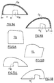
- FIGS. 9A and 9B show a front view of the left and right smooth windows G R and G L of elliptical headlights fitted to a motor vehicle, these windows G R and G L being each provided with an adaptation device 10 R and 10 L respectively, shown in Figures 10A and 10B. It can be seen in FIGS. 9A and 9B that the adaptation devices 10 R and 10 L are arranged on the smooth glass differently depending on whether one considers the right headlight or the left headlight of the vehicle.
- the present invention also provides for providing a fitting template, such as those which have been represented in FIGS. 11A and 11B for the headlamps the windows G R and G L of which are shown in FIGS. 9A and 9B.
- a fitting template such as those which have been represented in FIGS. 11A and 11B for the headlamps the windows G R and G L of which are shown in FIGS. 9A and 9B.
- each template 11 R and 11 L is adapted to the total shape of the protective glass of the dipped headlight for which it is intended, and that it delimits the second region of the protective glass , the one on which the adaptation device must be affixed. It is then easy for the user to install, without risk of error, the adaptation devices 10 R and 10 L to a change of direction of circulation.
- the template simply delimits the region of the headlamp protection glass on which the adaptation device must be placed.
- a template may consist of indication of the distance X or Y from the outer edge of the window to which it is suitable affix the adaptation device.
- the template may also consist of markers such only salient points, slight veins, screen printing, etc. on the glass of the projector.
- the glass G can be more or less inclined compared to vertically, more or less distant from the light source or the reflecting mirror, so that the adaptation device that has just been described may only provide an adaptation imperfect. We can then make such an adaptation device as shown in Figures 12 and 13.
- the adaptation device 10 can comprise several sections, in this case sections 20, 30, 40 and 50, each being carried out according to one of the modes described above.
- section 20 may consist of streaks at triangular profile, as in Figure 7A, section 30 of ridges with curvilinear profile, as in FIG. 7C, and the sections 40 and 50 of grooves with a substantially prismatic profile, as in Figure 7B.
- the angle at the top of the downward deflecting part may vary from one section to another, for example between sections 40 and 50.
- the downward deviating part of the adaptation device shown on Figure 12 can be made in the form of a Fresnel prism, as shown in Figures 5 and 8.
- this modification of the geometry of the beam is carried out only on the undesirable part of the beam, while preserving intact the part of the beam which is not likely to disturb other users.
- the half-cut C g is not affected by the method or the device according to the present invention, only the part F II of the beam located under the half-cut C d being adapted to adjust to the level of the half-cut C g .
- the adaptation device according to the present invention is thus arranged only on a part of the protective glass, so as to deflect vertically and horizontally only a part of the light beam emitted by the projector, in the manner of the holiday mask of the prior art.
- the adaptation device according to the present invention may be placed on a mask surface different from that which is constituted by the protective glass of the headlamp, in the event that such a surface exists upstream of the protective glass.
- the adaptation device can be made in the form of a flexible plastic adhesive film to be able to conform the curvature of the protective glass of the headlamp to be fitted. The characteristics of vertical and horizontal deviation of the device will then have been calculated to be optimal in such a non-planar configuration.
- the foregoing description is more particularly reported in the case where a beam for traffic on the right must be adapted for suitable for left-hand traffic, the skilled person will immediately be able to make the adaptations allowing to treat the opposite case.
Landscapes
- Engineering & Computer Science (AREA)
- General Engineering & Computer Science (AREA)
- Non-Portable Lighting Devices Or Systems Thereof (AREA)
Abstract
- déterminer sur la surface de la glace (G) au moins une première région (I) à travers laquelle passent les rayons lumineux situés en dessous de l'horizontale et au moins une deuxième région (II) à travers laquelle passent des rayons lumineux situés entre l'horizontale (Y'Y) et la demi-coupure (Cd),
- disposer sur la deuxième région (II) de la surface extérieure de la glace de protection (G) au moins un dispositif (10) modifiant le trajet des rayons lumineux passant par cette deuxième région (II),
- dévier vers le bas le trajet des rayons lumineux traversant la deuxième région (II) de glace (G) pour qu'ils soient situés en dessous de l'horizontale (Y'Y).
- dévier horizontalement les rayons lumineux traversant la deuxième région (II) de la surface de la glace de protection (G) pour qu'ils soient situés dans la partie (FI) du faisceau de croisement située en dessous de l'horizontale (Y'Y) et répartis dans cette partie (FI) du faisceau de croisement.
Description
- déterminer sur la surface extérieure de la glace de protection au moins une première région à travers laquelle passent les rayons lumineux correspondant à la partie du faisceau de croisement située en dessous de l'horizontale et au moins une deuxième région à travers laquelle passent des rayons lumineux correspondant à la partie du faisceau de croisement située entre l'horizontale et la demi-coupure située au-dessus de l'horizontale,
- disposer sur la deuxième région de la surface extérieure de la glace de protection au moins un dispositif modifiant le trajet des rayons lumineux passant par cette deuxième région,
- dévier vers le bas le trajet des rayons lumineux traversant la deuxième région de glace de protection pour qu'ils soient situés dans la partie du faisceau de croisement située en dessous de l'horizontale.
- la déviation du trajet des rayons lumineux passant par la deuxième région de la glace de protection du projecteur est effectuée par un élément transparent et déviateur de lumière ;
- l'élément transparent et déviateur de lumière comporte, lorsqu'il est en place sur le projecteur du véhicule, une première partie sensiblement prismatique déviant la lumière vers le bas et une deuxième partie déviant la lumière horizontalement ;
- au moins une des première ou deuxième parties est constituée par un prisme de Fresnel ;
- au moins une des première ou deuxième parties est constituée par des stries à profil curviligne.
- le dispositif comporte, lorsqu'il est en place sur le projecteur du véhicule, une première partie sensiblement prismatique déviant la lumière vers le bas et une deuxième partie déviant la lumière latéralement ;
- au moins une des première et deuxième parties est constituée par un prisme de Fresnel ;
- au moins une des première et deuxième parties est constituée par des stries à profil curviligne ;
- le dispositif est disposé sur la surface extérieure de la glace de protection du projecteur ;
- le dispositif comporte au moins deux sections comprenant chacune une première et une deuxième partie, l'angle au sommet de la première partie sensiblement prismatique de chaque section étant différent ;
- le dispositif comporte au moins deux sections comprenant chacune une première et une deuxième partie, le profil des stries de la deuxième partie de chaque section étant différent.
- la Figure 1 représente une vue schématique en coupe selon un plan vertical d'un projecteur du genre elliptique auquel est applicable la présente invention ;
- la Figure 2 représente une vue schématique en coupe selon un plan horizontal du projecteur de la Figure 1 ;
- les Figures 3A, 3B et 3C représentent chacune la trace d'un faisceau lumineux sur un écran disposé à distance et perpendiculairement à l'axe d'un projecteur respectivement avant adaptation du faisceau lumineux, et avec adaptation du faisceau lumineux selon un premier et un deuxième mode de réalisation de la présente invention ;
- la Figure 4 représente une vue en perspective un dispositif d'adaptation selon un premier mode de réalisation de la présente invention ;
- la Figure 5 représente une vue en perspective d'une variante de réalisation du dispositif d'adaptation de la Figure 4 ;
- la Figure 6 représente une vue en perspective d'un dispositif d'adaptation selon un deuxième mode de réalisation de la présente invention ;
- les Figure 7A, 7B et 7C représentent des vues en coupe de profils de stries utilisables dans le dispositif d'adaptation des Figures 5 et 6 ;
- la Figure 8 représente une vue en perspective d'un dispositif d'adaptation selon une variante du deuxième mode de réalisation de la présente invention ;
- les Figures 9A et 9B représentent une vue de face des glaces des projecteurs droit et gauche respectivement d'un véhicule automobile, munies chacune d'un dispositif d'adaptation selon la présente invention ;
- les Figures 10A et 10B représentent une vue en plan à échelle agrandie des dispositifs d'adaptation destinés à équiper les glaces des Figures 9A et 9B respectivement ;
- les Figures 11A et 11B représentent une vue en plan des gabarits de pose des dispositifs d'adaptation sur les glaces des Figures 9A et 9B respectivement ;
- la Figure 12 représente une vue en perspective d'un dispositif d'adaptation selon un troisième mode de réalisation de la présente invention, et
- la Figure 13 représente une vue en plan du dispositif d'adaptation de la Figure 12.
Claims (16)
- Procédé pour adapter un faisceau de croisement d'un projecteur du genre elliptique pour véhicule automobile à un sens de circulation inverse, le projecteur comportant, en amont d'une glace de protection (G) non déviatrice ou faiblement déviatrice de la lumière, une source lumineuse (S) émettant des rayons lumineux vers un miroir récupérateur et concentrateur (M) qui les renvoie en direction d'une lentille convergente (L) pour former, en coopération avec un cache (CA) un faisceau de croisement comportant de part et d'autre d'un axe optique (X'X) une demi-coupure (Cg) sensiblement horizontale s'étendant d'un côté de l'axe optique (X'X) et une demi-coupure (Cd) située au-dessus de l'horizontale (Y'Y) s'étendant de l'autre côté de l'axe optique (X'X), le procédé comportant les étapes consistant à :déterminer sur la surface extérieure de la glace de protection (G) au moins une première région (I) à travers laquelle passent les rayons lumineux correspondant à la partie (FI) du faisceau de croisement située en dessous de l'horizontale et au moins une deuxième région (II) à travers laquelle passent des rayons lumineux correspondant à la partie (FII) du faisceau de croisement située entre l'horizontale (Y'Y) et la demi-coupure (Cd) située au-dessus de l'horizontale (Y'Y),disposer sur la deuxième région (II) de la surface extérieure de la glace de protection (G) au moins un dispositif (10) modifiant le trajet des rayons lumineux passant par cette deuxième région (II),dévier vers le bas le trajet des rayons lumineux traversant la deuxième région (II) de glace de protection (G) pour qu'ils soient situés dans la partie (FI) du faisceau de croisement située en dessous de l'horizontale (Y'Y), le procédé étant caractérisé en ce qu'il comporte l'étape supplémentaire consistant à dévier horizontalement les rayons lumineux traversant la deuxième région (II) de la surface de la glace de protection (G) pour qu'ils soient situés dans la partie (FI) du faisceau de croisement située en dessous de l'horizontale (Y'Y) et répartis dans cette partie (FI) du faisceau de croisement.
- Procédé selon la revendication 1, caractérisé en ce que la déviation du trajet des rayons lumineux passant par la deuxième région (II) de la glace (G) de protection du projecteur est effectuée par un élément (10) transparent et déviateur de lumière.
- Procédé selon la revendication 2, caractérisé en ce que l'élément (10) transparent et déviateur de lumière comporte, lorsqu'il est en place sur le projecteur du véhicule, une première partie sensiblement prismatique déviant la lumière vers le bas et une deuxième partie déviant la lumière horizontalement
- Procédé selon la revendication 3, caractérisé en ce qu'au moins une des première ou deuxième parties est constituée par un prisme de Fresnel (16, 18).
- Procédé selon la revendication 3, caractérisé en ce qu'au moins une des première ou deuxième parties est constituée par des stries à profil curviligne (16, 18).
- Dispositif d'adaptation (10) pour la mise en oeuvre du procédé selon l'une quelconque des revendications précédentes, caractérisé en ce qu'il est destiné à être interposé sur le trajet d'une partie d'un faisceau lumineux émis par un projecteur de croisement du genre elliptique pour véhicule automobile comportant, en amont d'une glace de protection (G) non déviatrice ou faiblement déviatrice de la lumière, une source lumineuse (S) émettant des rayons lumineux vers un miroir récupérateur et concentrateur (M) qui les renvoie en direction d'une lentille convergente (L) pour former, en coopération avec un cache (CA) un faisceau de croisement comportant de part et d'autre d'un axe optique (X'X) une demi-coupure (Cg) sensiblement horizontale s'étendant d'un côté de l'axe optique (X'X) et une demi-coupure (Cd) située au-dessus de l'horizontale (Y'Y) s'étendant de l'autre côté de l'axe optique (X'X), le dispositif étant destiné à adapter la partie située au-dessus de l'horizontale (Y'Y) du faisceau lumineux émis par le projecteur de croisement lorsque le véhicule circule selon un sens de trafic inverse à celui pour lequel le projecteur a été conçu, et en ce qu'il est constitué d'un matériau transparent et déviateur de la lumière.
- Dispositif selon la revendication 6, caractérisé en ce qu'il comporte, lorsqu'il est en place sur le projecteur du véhicule, une première partie sensiblement prismatique déviant la lumière vers le bas et une deuxième partie déviant la lumière latéralement.
- Dispositif selon la revendication 7, caractérisé en ce qu'au moins une des première et deuxième parties est constituée par un prisme de Fresnel (16, 18).
- Dispositif selon la revendication 7, caractérisé en ce qu'au moins une des première et deuxième parties est constituée par des stries à profil curviligne (16, 18).
- Dispositif selon l'une quelconque des revendications 6 à 9, caractérisé en ce qu'il est disposé sur la surface extérieure de la glace (G) de protection du projecteur.
- Dispositif selon l'une quelconque des revendications 6 à 10, caractérisé en ce qu'il comporte au moins deux sections (20, 30, 40, 50) comprenant chacune une première et une deuxième partie, l'angle au sommet de la première partie sensiblement prismatique de chaque section (20, 30, 40, 50) étant différent.
- Dispositif selon l'une quelconque des revendications 6 à 10, caractérisé en ce qu'il comporte au moins deux sections (20, 30, 40, 50) comprenant chacune une première et une deuxième partie, le profil des stries de la deuxième partie de chaque section (20, 30, 40, 50) étant différent.
- Gabarit (11R, 11L) pour la mise en oeuvre du procédé selon l'une quelconque des revendications 1 à 5, caractérisé en ce qu'il délimite la deuxième région (II) de la glace (G) de protection du projecteur sur laquelle doit être disposé le dispositif (10) selon l'une quelconque des revendications 9 à 17.
- Gabarit selon la revendication 13, caractérisé en ce qu'il est adapté à la forme totale de la glace (G) de protection du projecteur de croisement et en ce qu'il délimite la deuxième région (II) de la glace (G) de protection du projecteur sur laquelle doit être disposé le dispositif (10) selon l'une quelconque des revendications 9 à 17.
- Projecteur de croisement du genre elliptique pour véhicule automobile, comportant, en amont d'une glace de protection (G) non déviatrice ou faiblement déviatrice de la lumière, une source lumineuse (S) émettant des rayons lumineux vers un miroir récupérateur et concentrateur (M) qui les renvoie en direction d'une lentille convergente (L) pour former, en coopération avec un cache (CA) un faisceau de croisement comportant de part et d'autre d'un axe optique (X'X) une demi-coupure (Cg) supérieure sensiblement horizontale s'étendant d'un côté de l'axe optique (X'X) et une demi-coupure (Cd) située au-dessus de l'horizontale (Y'Y) s'étendant de l'autre côté de l'axe optique (X'X), le faisceau de croisement étant susceptible d'être adapté selon un procédé conforme à l'une quelconque des revendications 1 à 5, caractérisé en ce que la glace (G) de protection est munie d'un gabarit (11R, 11L) selon l'une des revendications 13 ou 14.
- Projecteur de croisement pour véhicule automobile, comportant une source lumineuse (S) émettant des rayons lumineux vers un miroir réflecteur (M) qui les renvoie en direction d'une glace de protection (G) pour former, en coopération avec un cache (CA) un faisceau de croisement comportant de part et d'autre d'un axe optique (X'X) une demi-coupure (Cg) supérieure sensiblement horizontale s'étendant d'un côté de l'axe optique (X'X) et une demi-coupure (Cd) située au-dessus de l'horizontale (Y'Y) s'étendant de l'autre côté de l'axe optique (X'X), le faisceau de croisement étant susceptible d'être adapté selon un procédé conforme à l'une quelconque des revendications 1 à 5, caractérisé en ce que la glace (G) de protection est munie d'un dispositif (10) selon l'une quelconque des revendications 6 à 12.
Applications Claiming Priority (2)
| Application Number | Priority Date | Filing Date | Title |
|---|---|---|---|
| FR0007188 | 2000-05-31 | ||
| FR0007188A FR2809798B1 (fr) | 2000-05-31 | 2000-05-31 | Procede pour adapter un faisceau de croisement de projecteur elliptique a un sens de circulation inverse, dispositif, gabarit et projecteur pour la mise en oeuvre de ce procede |
Publications (2)
| Publication Number | Publication Date |
|---|---|
| EP1160505A1 true EP1160505A1 (fr) | 2001-12-05 |
| EP1160505B1 EP1160505B1 (fr) | 2007-01-10 |
Family
ID=8850985
Family Applications (1)
| Application Number | Title | Priority Date | Filing Date |
|---|---|---|---|
| EP01400962A Expired - Lifetime EP1160505B1 (fr) | 2000-05-31 | 2001-04-13 | Procédé pour adapter un faisceau de croisement de projecteur elliptique à un sens de circulation inverse, dispositif, gabarit et projecteur pour la mise en oeuvre de ce procédé |
Country Status (4)
| Country | Link |
|---|---|
| EP (1) | EP1160505B1 (fr) |
| DE (1) | DE60125863T2 (fr) |
| ES (1) | ES2280323T3 (fr) |
| FR (1) | FR2809798B1 (fr) |
Citations (8)
| Publication number | Priority date | Publication date | Assignee | Title |
|---|---|---|---|---|
| GB1462044A (en) * | 1973-02-26 | 1977-01-19 | Schmidt N | Headlamp converters |
| FR2428204A1 (fr) * | 1978-06-09 | 1980-01-04 | Cibie Projecteurs | Perfectionnements aux glaces de projecteurs automobiles comportant des stries de deviation de lumiere |
| FR2542422A1 (fr) * | 1983-03-08 | 1984-09-14 | Cibie Projecteurs | Projecteur d'automobile a glace inclinee munie d'elements optiques redresseurs |
| DE4202762A1 (de) * | 1992-01-31 | 1993-08-05 | Hella Kg Hueck & Co | Scheinwerfer fuer fahrzeuge |
| FR2704044A1 (fr) | 1993-04-15 | 1994-10-21 | Valeo Vision | Projecteur du genre elliptique pour véhicule automobile. |
| FR2773604A1 (fr) | 1998-01-09 | 1999-07-16 | Valeo Vision | Projecteur du genre elliptique pour vehicule automobile |
| DE19830396A1 (de) * | 1998-07-08 | 2000-02-10 | Bosch Gmbh Robert | Scheinwerferanordnung für Kraftfahrzeuge |
| GB2350671A (en) * | 1999-04-10 | 2000-12-06 | Bosch Gmbh Robert | Optical element for attachment to a headlamp glass of a motor vehicle |
-
2000
- 2000-05-31 FR FR0007188A patent/FR2809798B1/fr not_active Expired - Fee Related
-
2001
- 2001-04-13 DE DE60125863T patent/DE60125863T2/de not_active Expired - Lifetime
- 2001-04-13 EP EP01400962A patent/EP1160505B1/fr not_active Expired - Lifetime
- 2001-04-13 ES ES01400962T patent/ES2280323T3/es not_active Expired - Lifetime
Patent Citations (8)
| Publication number | Priority date | Publication date | Assignee | Title |
|---|---|---|---|---|
| GB1462044A (en) * | 1973-02-26 | 1977-01-19 | Schmidt N | Headlamp converters |
| FR2428204A1 (fr) * | 1978-06-09 | 1980-01-04 | Cibie Projecteurs | Perfectionnements aux glaces de projecteurs automobiles comportant des stries de deviation de lumiere |
| FR2542422A1 (fr) * | 1983-03-08 | 1984-09-14 | Cibie Projecteurs | Projecteur d'automobile a glace inclinee munie d'elements optiques redresseurs |
| DE4202762A1 (de) * | 1992-01-31 | 1993-08-05 | Hella Kg Hueck & Co | Scheinwerfer fuer fahrzeuge |
| FR2704044A1 (fr) | 1993-04-15 | 1994-10-21 | Valeo Vision | Projecteur du genre elliptique pour véhicule automobile. |
| FR2773604A1 (fr) | 1998-01-09 | 1999-07-16 | Valeo Vision | Projecteur du genre elliptique pour vehicule automobile |
| DE19830396A1 (de) * | 1998-07-08 | 2000-02-10 | Bosch Gmbh Robert | Scheinwerferanordnung für Kraftfahrzeuge |
| GB2350671A (en) * | 1999-04-10 | 2000-12-06 | Bosch Gmbh Robert | Optical element for attachment to a headlamp glass of a motor vehicle |
Also Published As
| Publication number | Publication date |
|---|---|
| ES2280323T3 (es) | 2007-09-16 |
| EP1160505B1 (fr) | 2007-01-10 |
| FR2809798B1 (fr) | 2002-11-29 |
| DE60125863T2 (de) | 2007-10-25 |
| FR2809798A1 (fr) | 2001-12-07 |
| DE60125863D1 (de) | 2007-02-22 |
Similar Documents
| Publication | Publication Date | Title |
|---|---|---|
| EP3301348B1 (fr) | Dispositif d'éclairage en bandes pour projecteur de véhicule automobile | |
| EP2006605B1 (fr) | Module optique pour dispositif d'éclairage automobile | |
| EP1369639B1 (fr) | Projecteur d'éclairage elliptique comportant une source lumineuse secondaire | |
| EP1308669A1 (fr) | Dispositif d'éclairage de type elliptique pour véhicule automobile | |
| FR2787863A1 (fr) | Installation de projecteurs pour vehicules generant des faisceaux lumineux a caracteristiques differentes | |
| EP1449716B1 (fr) | Dispositif d'éclairage pour un véhicule automobile | |
| EP1197387A1 (fr) | Projecteur pour véhicule automobile à écran d'occultation mobile | |
| FR2819578A1 (fr) | Phare de vehicule a eclairage reglable lateralement | |
| EP1564482B1 (fr) | Projecteur elliptique équipé d'un écran d'occultation en matière transparente | |
| FR2855245A1 (fr) | Phare de vehicule a obturateur pivotant | |
| FR2787864A1 (fr) | Projecteur permettant une attenuation de l'eclairage de la zone proche a l'avant du vehicule | |
| FR2769071A1 (fr) | Projecteur de type elliptique a faisceau variable, notamment pour vehicule automobile | |
| EP1442928B1 (fr) | Dispositif d'éclairage comportant des moyens pour compenser la défaillance d'un code virage | |
| EP3350507B1 (fr) | Dispositif d'éclairage pour véhicules automobiles | |
| EP1422471A2 (fr) | Projecteur elliptique pour véhicule automobile émettant des faisceaux d'éclairage différents | |
| EP0684420B1 (fr) | Projecteur comportant une lampe à deux filaments pour engendrer un faisceau coupé et un faisceau non coupé | |
| EP1170546A1 (fr) | Projecteur elliptique à modification de faisceau par mouvement d'éléments optiques | |
| EP1348594B1 (fr) | Projecteur d'éclairage équipé d'un réflecteur elliptique pivotant et d'une lentille fixe pour la réalisation d'un faisceau de virage | |
| FR2773604A1 (fr) | Projecteur du genre elliptique pour vehicule automobile | |
| EP1870283B1 (fr) | Ensemble projecteur à trois fonctions pour véhicule automobile | |
| EP1160505B1 (fr) | Procédé pour adapter un faisceau de croisement de projecteur elliptique à un sens de circulation inverse, dispositif, gabarit et projecteur pour la mise en oeuvre de ce procédé | |
| EP1160504B1 (fr) | Procédé pour adapter un faisceau de projecteur de croisement à un sens de circulation inverse, dispositif, gabarit et projecteur pour la mise en oeuvre de ce procédé | |
| FR2793001A1 (fr) | Projecteur de vehicule automobile susceptible d'emettre un faisceau de croisement et un faisceau de croisement modifie pour circulation autoroutiere | |
| EP1288563A1 (fr) | Dispositif d'éclairage réalisant un faisceau d'éclairage pour la circulation par temps pluvieux | |
| FR2491196A1 (fr) | Phare pour vehicule automobile |
Legal Events
| Date | Code | Title | Description |
|---|---|---|---|
| PUAI | Public reference made under article 153(3) epc to a published international application that has entered the european phase |
Free format text: ORIGINAL CODE: 0009012 |
|
| AK | Designated contracting states |
Kind code of ref document: A1 Designated state(s): AT BE CH CY DE DK ES FI FR GB GR IE IT LI LU MC NL PT SE TR Kind code of ref document: A1 Designated state(s): DE ES GB IT |
|
| AX | Request for extension of the european patent |
Free format text: AL;LT;LV;MK;RO;SI |
|
| 17P | Request for examination filed |
Effective date: 20020531 |
|
| AKX | Designation fees paid |
Free format text: DE ES GB IT |
|
| GRAP | Despatch of communication of intention to grant a patent |
Free format text: ORIGINAL CODE: EPIDOSNIGR1 |
|
| GRAS | Grant fee paid |
Free format text: ORIGINAL CODE: EPIDOSNIGR3 |
|
| GRAA | (expected) grant |
Free format text: ORIGINAL CODE: 0009210 |
|
| AK | Designated contracting states |
Kind code of ref document: B1 Designated state(s): DE ES GB IT |
|
| REG | Reference to a national code |
Ref country code: GB Ref legal event code: FG4D Free format text: NOT ENGLISH |
|
| REF | Corresponds to: |
Ref document number: 60125863 Country of ref document: DE Date of ref document: 20070222 Kind code of ref document: P |
|
| GBT | Gb: translation of ep patent filed (gb section 77(6)(a)/1977) |
Effective date: 20070222 |
|
| REG | Reference to a national code |
Ref country code: ES Ref legal event code: FG2A Ref document number: 2280323 Country of ref document: ES Kind code of ref document: T3 |
|
| PLBE | No opposition filed within time limit |
Free format text: ORIGINAL CODE: 0009261 |
|
| STAA | Information on the status of an ep patent application or granted ep patent |
Free format text: STATUS: NO OPPOSITION FILED WITHIN TIME LIMIT |
|
| 26N | No opposition filed |
Effective date: 20071011 |
|
| PGFP | Annual fee paid to national office [announced via postgrant information from national office to epo] |
Ref country code: DE Payment date: 20120416 Year of fee payment: 12 |
|
| PGFP | Annual fee paid to national office [announced via postgrant information from national office to epo] |
Ref country code: GB Payment date: 20120423 Year of fee payment: 12 |
|
| PGFP | Annual fee paid to national office [announced via postgrant information from national office to epo] |
Ref country code: IT Payment date: 20120423 Year of fee payment: 12 |
|
| PGFP | Annual fee paid to national office [announced via postgrant information from national office to epo] |
Ref country code: ES Payment date: 20120425 Year of fee payment: 12 |
|
| GBPC | Gb: european patent ceased through non-payment of renewal fee |
Effective date: 20130413 |
|
| PG25 | Lapsed in a contracting state [announced via postgrant information from national office to epo] |
Ref country code: DE Free format text: LAPSE BECAUSE OF NON-PAYMENT OF DUE FEES Effective date: 20131101 Ref country code: GB Free format text: LAPSE BECAUSE OF NON-PAYMENT OF DUE FEES Effective date: 20130413 |
|
| REG | Reference to a national code |
Ref country code: DE Ref legal event code: R119 Ref document number: 60125863 Country of ref document: DE Effective date: 20131101 |
|
| PG25 | Lapsed in a contracting state [announced via postgrant information from national office to epo] |
Ref country code: IT Free format text: LAPSE BECAUSE OF NON-PAYMENT OF DUE FEES Effective date: 20130413 |
|
| REG | Reference to a national code |
Ref country code: ES Ref legal event code: FD2A Effective date: 20140606 |
|
| PG25 | Lapsed in a contracting state [announced via postgrant information from national office to epo] |
Ref country code: ES Free format text: LAPSE BECAUSE OF NON-PAYMENT OF DUE FEES Effective date: 20130414 |