EP1160167A2 - Process and machine for exact positioning of a web of foil lids on moulded packages - Google Patents
Process and machine for exact positioning of a web of foil lids on moulded packages Download PDFInfo
- Publication number
- EP1160167A2 EP1160167A2 EP01103721A EP01103721A EP1160167A2 EP 1160167 A2 EP1160167 A2 EP 1160167A2 EP 01103721 A EP01103721 A EP 01103721A EP 01103721 A EP01103721 A EP 01103721A EP 1160167 A2 EP1160167 A2 EP 1160167A2
- Authority
- EP
- European Patent Office
- Prior art keywords
- photocell
- film
- brake
- cover film
- strip
- Prior art date
- Legal status (The legal status is an assumption and is not a legal conclusion. Google has not performed a legal analysis and makes no representation as to the accuracy of the status listed.)
- Withdrawn
Links
Images


Classifications
-
- B—PERFORMING OPERATIONS; TRANSPORTING
- B65—CONVEYING; PACKING; STORING; HANDLING THIN OR FILAMENTARY MATERIAL
- B65B—MACHINES, APPARATUS OR DEVICES FOR, OR METHODS OF, PACKAGING ARTICLES OR MATERIALS; UNPACKING
- B65B41/00—Supplying or feeding container-forming sheets or wrapping material
- B65B41/18—Registering sheets, blanks, or webs
Definitions
- the present invention relates to a method and an apparatus for cyclical Positioning images over packaging trays printed on a lidding film are.
- Packaging especially food packaging, is gaining one these days ever greater importance. These packages often consist of one Packaging tray into which the packaged goods, for example food, are filled be and on which a cover film is sealed so that the goods to be packaged is airtight.
- the packaging troughs are used in cycles to seal conveyed from a servo chain drive system into the so-called sealing station, the lid film is sealed onto the packaging trough and then as finished packaging transported further by the servo chain drive system. Since the cover film after the Sealing is firmly connected to the packaging tray, the lid film is at Further transport of the finished packaging unrolled from a roll in cycles.
- the task, a method and a device are therefore available with which images that are printed on cover foils exactly over Packaging trays can be positioned.
- the cover film is any cover film known to the person skilled in the art which is produced by a Roll is unrolled and printed with pictures.
- An image in the sense of the invention is any printable representation of z. B. products, advertising slogans and / or Company logos.
- the pictures are at a certain distance from each other, so that there is an unprinted stripe between two pictures.
- the method according to the invention are only the unprinted strips which run across extend to the direction of the cover film, relevant.
- the lidding film is filled with packaging material in the sealing station Sealed packaging troughs.
- the packaging trays are intermittently z. B. transported to the sealing station with a servo chain drive, the cover film on the packaging trough sealed and the packaging thus obtained with the servo chain drive transported by a precisely defined amount, so that the subsequent packaging troughs can be sealed.
- the lidding film is firmly connected to the packaging tray, the lid film is during further transport the finished packaging unrolled from the roll. The expert understands that this unrolling takes place in cycles.
- the packaging is separated in a cutting station cut.
- the exact positioning of the images takes place via the Packaging trays with a first and a second photocell and a film brake, which is arranged between the two photocells.
- the second photocell Related to the The direction of the cover film is the second photocell behind the film brake.
- the second photocell checks whether it is one strip perpendicular to the direction of the film, which is between two Pictures. If this is the case, the print images have advanced and the first photocell is activated so that it in turn activates the film brake, as soon as the first photocell has a streak between two passing images recognized.
- any film brake known to the person skilled in the art can be used as the film brake be used.
- the time of activation of the first photocell is freely selectable, but should be first take place when the cover film is already being transported; i.e. at the next Clock.
- the first photocell is preferably activated shortly before the Feed of the finished packaging and thus the lidding film is finished. Activation is particularly preferably 40 to 100 mm, very particularly preferably 50 to 80 mm before the feed of the cover film has ended.
- first photocell can be moved along the x-axis (see FIG. 3). Because of this The time at which a strip is recognized can be shifted. If the photocell is moved against the direction of the film, the time will be the detection of a strip preferred, so that the cover film after actuation the film brake is stretched more because the remaining feed of the Cover film is longer. If the photocell is moved in the direction of the film, the time of detection of a strip is delayed and, accordingly, the cover film stretched less after applying the film brake.
- the cover film is between each two images printed marks then printed instead of the strips for positioning of the images are used. The positioning follows the positioning With stripes.
- the method according to the invention has the advantage that pictures can be obtained in a very simple manner be positioned very precisely on cover foils with a deviation of ⁇ 0.5 mm can.
- the method can be carried out with very little effort and has proved to be very robust. Despite the film change and the machine at a standstill could the method according to the invention over a very long period of trouble be used.
- Another object of the present invention is a device for cyclical, exact positioning of images printed on a cover film over packaging trays with a first and a second photocell and with a film brake, which is arranged between the photocells.
- any film brake known to the person skilled in the art can be used as the film brake be used.
- the second photocell is located in relation to the running direction of the cover film behind the film brake.
- the second photocell is preferably based on the Direction of the film, immediately before the sealing device or after the sealing device arranged.
- the second photocell detects each time it stops the position of the cover film, preferably during the sealing Strip and / or a print mark and activated depending on it if necessary the first photocell, which in turn, if activated, controls the film brake, as soon as they pass a stripe and / or a print mark between two Recognized images.
- the time of activation of the first photocell is freely selectable, but should be first take place when the cover film is already being transported; i.e. at the next Clock.
- the first photocell is preferably activated shortly before the Feed of the finished packaging and thus the lidding film is finished. Activation is particularly preferably 40 to 100 mm, very particularly preferably 50 to 80 mm before the feed of the cover film has ended.
- first photocell can be moved along the x-axis (see FIG. 3). Because of this The time at which a strip is recognized can be shifted. If the photocell is moved against the direction of the film, the time will be the detection of a strip preferred, so that the cover film after actuation the film brake is stretched more because the remaining feed of the Cover film is longer. If the photocell is moved in the direction of the film, the time of detection of a strip is delayed and, accordingly, the cover film stretched less after applying the film brake.
- the recognition hysteresis of the second photocell is preferably, in particular however, preferably both photocells ⁇ 0.4 mm, preferably ⁇ 0.25 mm, particularly preferably ⁇ 0.15 mm, measured at a normal distance of 9.5 mm between Lens and film.
- the device according to the invention is advantageously operated by a programmable logic controller (PLC) controlled. Control is also preferred using a personal computer or a microprocessor.
- PLC programmable logic controller
- the device according to the invention has the advantage that images are generated in a very simple manner be positioned very precisely on cover foils with a deviation of ⁇ 0.5 mm can.
- the device is very easy to set up and has proven to be very robust proven. Despite changing the film and the machine at a standstill, the invention Device can be used without problems over a very long period.
- Another object of the present invention is a film brake with three Rolls over which the film runs and two brake means. Based on the direction of travel In the film, the rolls are arranged one after the other, the middle roll being different Direction of rotation has as the two outer rollers. The two outer roles preferably interact with the two braking means. Preferably the middle roll is slidably mounted.
- the braking means are preferably driven pneumatically or electrically.
- the film brake according to the invention is from the first photocell of the device according to the invention for positioning Images on packaging trays activated.
- the film brake according to the invention is simple and inexpensive to manufacture.
- the Foil brake has a very short response time. Slipping through the film the film brake is excluded.
- the film brake according to the invention has proven to be very robust.
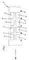
- Figure 1 shows a cover film, which is printed with pictures.
- FIG. 2 shows a cover film printed with pictures, which additionally has print marks.
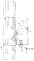
- Figure 3 shows a sealing station with the positioning device according to the invention.
- Figure 4 shows the film brake according to the invention.
- Figure 1 shows a cover film 1, on which pictures 3 are printed.
- the pictures 3 are printed at a certain distance from one another on the cover film, so that strips 2 are produced transversely to the running direction of the film (represented by the arrow).
- the strips in the running direction of the film are irrelevant to the present invention.
- the cover film according to FIG. 2 essentially corresponds to the cover film according to FIG. 1, the cover film according to FIG. 2 additionally having print marks 9.
- Figure 3 shows a sealing station with the positioning device according to the invention.
- the packaging troughs 4 filled with packaging material are conveyed in cycles by a servo chain drive into the sealing station in order to be sealed there with a cover film 1 in the sealing device 11.
- the packs 8 thus finished are conveyed by the servo chain drive to a cutting station (not shown) in cycles, each time by a fixed amount.
- the cover film 1 is rolled off the roll 17 in cycles.
- the positioning device consists of a first and a second photocell (5, 6) and a film brake arranged between the photocells 7.
- the second photocell 6 is, based on the running direction of the cover film, arranged immediately in front of the sealing device 11.
- the lidding film runs with the printed side directly past the photocells 5, 6 and partially encloses the rollers of the film brake 7.
- the photocells 5, 6 are products of the Visolux company Electronics GmbH, Prinzenstr. 85, 10969 Berlin and have a recognition hysteresis of 0.1 mm, measured at a distance of 9.5 mm between the lens and the film.
- the positioning according to the invention is controlled by a PLC.
- the PLC queries whether the second photocell 6 is one Strip 2 or a print mark 9 recognizes. If this is the case, it knows System that the picture 3 has advanced.
- the photocell 5 is activated by the PLC.
- the first photocell 5 in turn activates the film brake 7 as soon as it is one Strip 2 or a print mark 9 between two passing images 3 recognized Has. Due to the film brake 7, the further transport of the cover film 1 at the location of the Foil brake 7 stopped abruptly while the packaging 8 was still being fed something lasts so that the cover film 1 between the last sealed Package 8 and the film brake 7 is stretched.
- the Pictures based on the running direction of the cover film 1, pulled back a little. This process is repeated until the second photocell 6 during the Standstill of the cover film 1 no longer recognizes a strip 2 or a print mark 9. If the second photocell 6 does not recognize a strip 2 or a print mark 9, becomes the first photocell 5 and thus the film brake at the next cycle not activated.
- Figure 4 shows the film brake 7 according to the invention with three rollers 12-14 and two brake discs 15 and 16, which cooperate with the rollers 12 and 14.
- the roller 13 is slidably mounted so that the wrap angle of the rollers can be adjusted through the cover film.
- the brake discs are driven by two pneumatic cylinders.
- the film brake according to the invention is activated by the first photocell 5.
Abstract
Description
Die vorliegende Erfindung betrifft ein Verfahren und eine Vorrichtung zur taktweisen Positionierung von Bildern über Verpackungsmulden, die auf eine Deckelfolie gedruckt sind.The present invention relates to a method and an apparatus for cyclical Positioning images over packaging trays printed on a lidding film are.
Verpackungen, insbesondere Lebensmittelverpackungen, gewinnen heutzutage eine immer größere Bedeutung. Diese Verpackungen bestehen oftmals aus einer Verpackungsmulde, in die das Verpackungsgut, beispielsweise Lebensmittel, eingefüllt werden und auf die eine Deckelfolie gesiegelt wird, damit das Verpackungsgut luftdicht abgeschlossen ist. Zum Siegeln werden die Verpackungsmulden taktweise von einem Servo-Kettenantriebssystem in die sogenannte Siegelstation gefördert, die Deckelfolie auf die Verpackungsmulde gesiegelt und dann als fertige Verpackung vom Servo-Kettenantriebssystem weiter transportiert. Da die Deckelfolie nach dem Siegeln fest mit der Verpackungsmulde verbunden ist, wird die Deckelfolie beim Weitertransport der fertigen Verpackung taktweise von einer Rolle abgerollt.Packaging, especially food packaging, is gaining one these days ever greater importance. These packages often consist of one Packaging tray into which the packaged goods, for example food, are filled be and on which a cover film is sealed so that the goods to be packaged is airtight. The packaging troughs are used in cycles to seal conveyed from a servo chain drive system into the so-called sealing station, the lid film is sealed onto the packaging trough and then as finished packaging transported further by the servo chain drive system. Since the cover film after the Sealing is firmly connected to the packaging tray, the lid film is at Further transport of the finished packaging unrolled from a roll in cycles.
Heutzutage werden als Deckelfolien immer öfter Folien verwendet, die mit Bildern bedruckt sind, die sich nahezu über den gesamten Querschnitt der Verpackungsmulde erstrecken, damit die Verpackungen ansprechender aussehen. Da die Bilder nahezu dieselbe Größe wie die Verpackungsmulde haben, auf die sie gesiegelt werden, müssen die Bilder mit einer Toleranz von ± 0,5 mm positioniert werden, was sich in der Vergangenheit als nicht realisierbar herausgestellt hat, weil sich z. B. der Füllzustand der Verpackungsmulden und damit die benötigte Länge der Deckelfolie sowie das Dehnverhalten der Folie in Abhängigkeit von der Temperatur bzw. der Luftfeuchtigkeit ständig verändert.Nowadays, films with pictures are used more and more as cover films are printed, which cover almost the entire cross section of the packaging tray stretch to make the packaging look more appealing. Because the pictures are almost the same size as the packaging tray on which they are sealed, the images must be positioned with a tolerance of ± 0.5 mm, what has proven to be impossible in the past because e.g. B. the Filling status of the packaging troughs and thus the required length of the cover film as well as the stretching behavior of the film depending on the temperature or Humidity is constantly changing.
Es stellt sich deshalb die Aufgabe, ein Verfahren und eine Vorrichtung zur Verfügung zu stellen, mit denen Bilder, die auf Deckelfolien gedruckt sind, exakt über Verpackungsmulden positioniert werden können.The task, a method and a device are therefore available with which images that are printed on cover foils exactly over Packaging trays can be positioned.
Die Aufgabe wird erfindungsgemäß durch ein Verfahren zur taktweisen exakten Positionierung von auf eine Deckelfolie in einem gewissen Abstand unter Einhaltung eines unbedruckten Streifens aufgedruckten Bildern über Verpackungsmulden mit einer Vorrichtung, die aus einer ersten und einer zweiten Photozelle und einer zwischen den Photozellen angeordneten Folienbremse besteht, gelöst, wobei die Deckelfolie nach dem Positionieren auf die Verpackungsmulde gesiegelt wird und die so erhaltene Verpackung und damit die Deckelfolie danach um ein festgelegtes Maß weiter transportiert wird, bei dem:
- während jedes Stillstands der Folie, vorzugsweise während des Siegelns ermittelt wird, ob die zweite Photozelle einen Streifen erkennt, und bei Erkennen eines Streifens die erste Photozelle aktiviert wird,
- während des Weitertransports der Deckelfolie die erste Photozelle die Folienbremse ansteuert, sobald sie einen Streifen zwischen zwei vorbeilaufenden Bildern erkannt hat, so daß der Weitertransport der Deckelfolie am Ort der Folienbremse gestoppt und die Deckelfolie aufgrund des andauernden Vorschubs der zuletzt gesiegelten Verpackung gedehnt wird.
- during each standstill of the film, preferably during the sealing, it is determined whether the second photocell recognizes a streak, and when a stripe is recognized, the first photocell is activated,
- during the further transport of the cover film, the first photocell controls the film brake as soon as it detects a streak between two passing images, so that the further transport of the cover film is stopped at the location of the film brake and the cover film is stretched due to the continuous advance of the last sealed packaging.
Die Deckelfolie ist jede beliebige, dem Fachmann bekannte Deckelfolie, die von einer Rolle abgerollt wird und die mit Bildern bedruckt ist. Ein Bild im Sinne der Erfindung ist jede beliebige druckbare Darstellung von z. B. Produkten, Werbeslogans und/oder Firmenlogos. Die Bilder weisen untereinander jeweils einen gewissen Abstand auf, so daß sich jeweils zwischen zwei Bildern ein unbedruckter Streifen ergibt. Für das erfindungsgemäße Verfahren sind lediglich die unbedruckten Streifen, die sich quer zur Laufrichtung der Deckelfolie erstrecken, relevant.The cover film is any cover film known to the person skilled in the art which is produced by a Roll is unrolled and printed with pictures. An image in the sense of the invention is any printable representation of z. B. products, advertising slogans and / or Company logos. The pictures are at a certain distance from each other, so that there is an unprinted stripe between two pictures. For the The method according to the invention are only the unprinted strips which run across extend to the direction of the cover film, relevant.
Die Deckelfolie wird in der Siegelstation auf mit Verpackungsgut gefüllte Verpackungsmulden gesiegelt. Dafür werden die Verpackungsmulden taktweise z. B. mit einem Servo-Kettenantrieb in die Siegelstation transportiert, die Deckelfolie auf die Verpackungsmulde gesiegelt und die so erhaltene Verpackung mit dem Servo-Kettenantrieb um ein genau festgelegtes Maß weiter transportiert, damit dann die nachfolgenden Verpackungsmulden gesiegelt werden können. Da die Deckelfolie fest mit der Verpackungsmulde verbunden ist, wird die Deckelfolie beim Weitertransport der fertigen Verpackung zwangsweise von der Rolle abgerollt. Der Fachmann versteht, daß dieses Abrollen taktweise erfolgt. The lidding film is filled with packaging material in the sealing station Sealed packaging troughs. For this, the packaging trays are intermittently z. B. transported to the sealing station with a servo chain drive, the cover film on the packaging trough sealed and the packaging thus obtained with the servo chain drive transported by a precisely defined amount, so that the subsequent packaging troughs can be sealed. Because the lidding film is firmly connected to the packaging tray, the lid film is during further transport the finished packaging unrolled from the roll. The expert understands that this unrolling takes place in cycles.
Nach dem Siegeln werden die Verpackungen in einer Schneidstation auseinander geschnitten.After sealing, the packaging is separated in a cutting station cut.
Erfindungsgemäß erfolgt die exakte Positionierung der Bilder über den Verpackungsmulden mit einer ersten und einer zweiten Photozelle sowie einer Folienbremse, die zwischen den beiden Photozellen angeordnet ist. Bezogen auf die Laufrichtung der Deckelfolie befindet sich die zweite Photozelle hinter der Folienbremse. Während jedes Stillstands der Deckelfolie, vorzugsweise beim Siegeln der Deckelfolie auf die Verpackungsmulde, überprüft die zweite Photozelle, ob sie einen senkrecht zur Laufrichtung der Folie verlaufenden Streifen, der sich zwischen zwei Bildern befindet, erkennt. Falls dies der Fall ist, sind die Druckbilder vorgelaufen und die erste Photozelle wird aktiviert, damit diese wiederum die Folienbremse aktiviert, sobald die erste Photozelle einen Streifen zwischen zwei vorbeilaufenden Bildern erkannt hat.According to the invention, the exact positioning of the images takes place via the Packaging trays with a first and a second photocell and a film brake, which is arranged between the two photocells. Related to the The direction of the cover film is the second photocell behind the film brake. During each standstill of the cover film, preferably when sealing the Cover film on the packaging tray, the second photocell checks whether it is one strip perpendicular to the direction of the film, which is between two Pictures. If this is the case, the print images have advanced and the first photocell is activated so that it in turn activates the film brake, as soon as the first photocell has a streak between two passing images recognized.
Als Folienbremse kann jede beliebige, dem Fachmann bekannte Folienbremse eingesetzt werden.Any film brake known to the person skilled in the art can be used as the film brake be used.
Durch das Bremsen während des Weitertransports wird die Deckelfolie zwischen der Folienbremse und der zuletzt gesiegelten Verpackung gedehnt, so daß die Position des Bildes, das als nächstes auf eine Verpackungsmulde gesiegelt werden soll, bezogen auf die Laufrichtung der Deckelfolie, weiter zurückversetzt wird. Dieser Vorgang wird bei jedem Takt und solange wiederholt, bis die zweite Photozelle keine Streifen mehr erkennt und wieder begonnen, sobald die zweite Photozelle wieder einen Streifen erkennt.By braking during further transport, the cover film between the Film brake and the last sealed package stretched so that the position of the image to be sealed next to a packaging tray on the running direction of the cover film, is set back further. This process is repeated with every cycle and until the second photocell does not Detects more stripes and started again as soon as the second photocell again recognizes a streak.
Der Zeitpunkt der Aktivierung der ersten Photozelle ist frei wählbar, sollte aber erst erfolgen, wenn die Deckelfolie bereits weiter transportiert wird; d.h. beim nächsten Takt. Vorzugsweise erfolgt die Aktivierung der ersten Photozelle kurz bevor der Vorschub der fertigen Verpackungen und damit der Deckelfolie beendet ist. Besonders bevorzugt erfolgt die Aktivierung 40 bis 100 mm, ganz besonders bevorzugt 50 bis 80 mm, bevor der Vorschub der Deckfolie beendet ist. The time of activation of the first photocell is freely selectable, but should be first take place when the cover film is already being transported; i.e. at the next Clock. The first photocell is preferably activated shortly before the Feed of the finished packaging and thus the lidding film is finished. Activation is particularly preferably 40 to 100 mm, very particularly preferably 50 to 80 mm before the feed of the cover film has ended.
In einer bevorzugten Ausführungsform des erfindungsgemäßen Verfahrens ist die erste Photozelle entlang der x-Achse (vgl. Figur 3) verschiebbar. Durch dieses Verschieben kann der Zeitpunkt des Erkennens eines Streifens verändert werden. Wird die Photozelle gegen die Laufrichtung der Folie verschoben, wird der Zeitpunkt der Erkennung eines Streifens vorgezogen, so daß die Deckelfolie nach Betätigung der Folienbremse stärker gedehnt wird, weil der verbleibende Vorschub der Deckelfolie länger ist. Wird die Photozelle in Laufrichtung der Folie verschoben, wird der Zeitpunkt des Erkennens eines Streifens verzögert und demnach die Deckelfolie nach Betätigung der Folienbremse weniger gedehnt.In a preferred embodiment of the method according to the invention first photocell can be moved along the x-axis (see FIG. 3). Because of this The time at which a strip is recognized can be shifted. If the photocell is moved against the direction of the film, the time will be the detection of a strip preferred, so that the cover film after actuation the film brake is stretched more because the remaining feed of the Cover film is longer. If the photocell is moved in the direction of the film, the time of detection of a strip is delayed and, accordingly, the cover film stretched less after applying the film brake.
In einer bevorzugten Ausführungsform werden auf die Deckelfolie jeweils zwischen zwei Bildern Druckmarken gedruckt, die dann anstatt der Streifen für die Positionierung der Bilder eingesetzt werden. Die Positionierung erfolgt anlog der Positionierung mit Streifen.In a preferred embodiment, the cover film is between each two images printed marks then printed instead of the strips for positioning of the images are used. The positioning follows the positioning With stripes.
Das erfindungsgemäße Verfahren hat den Vorteil, daß auf sehr einfache Weise Bilder auf Deckelfolien sehr exakt mit einer Abweichung ≤ 0,5 mm positioniert werden können. Das Verfahren ist mit einem sehr geringen Aufwand durchführbar und hat sich als sehr robust erwiesen. Trotz Folienwechsel und Stillstand der Maschine konnte das erfindungsgemäße Verfahren über einen sehr langen Zeitraum störungsfrei eingesetzt werden.The method according to the invention has the advantage that pictures can be obtained in a very simple manner be positioned very precisely on cover foils with a deviation of ≤ 0.5 mm can. The method can be carried out with very little effort and has proved to be very robust. Despite the film change and the machine at a standstill could the method according to the invention over a very long period of trouble be used.
Ein weiterer Gegenstand der vorliegenden Erfindung ist eine Vorrichtung zur taktweisen, exakten Positionierung von auf eine Deckelfolie gedruckten Bildern über Verpackungsmulden mit einer ersten und einer zweiten Photozelle und mit einer Folienbremse, die zwischen den Photozellen angeordnet ist.Another object of the present invention is a device for cyclical, exact positioning of images printed on a cover film over packaging trays with a first and a second photocell and with a film brake, which is arranged between the photocells.
Als Folienbremse kann jede beliebige, dem Fachmann bekannte Folienbremse eingesetzt werden.Any film brake known to the person skilled in the art can be used as the film brake be used.
Bezogen auf die Laufrichtung der Deckelfolie befindet sich die zweite Photozelle hinter der Folienbremse. Vorzugsweise ist die zweite Photozelle, bezogen auf die Laufrichtung der Folie, unmittelbar vor der Siegelvorrichtung oder nach der Siegelvorrichtung angeordnet. The second photocell is located in relation to the running direction of the cover film behind the film brake. The second photocell is preferably based on the Direction of the film, immediately before the sealing device or after the sealing device arranged.
In einer bevorzugten Ausführungsform ermittelt die zweite Photozelle bei jedem Stillstand der Deckelfolie vorzugsweise während des Siegelns die Position eines Streifens und/oder einer Druckmarke und aktiviert abhängig davon gegebenenfalls die erste Photozelle, die ihrerseits, sofern aktiviert, die Folienbremse ansteuert, sobald sie einen Streifen und/oder eine Druckmarke zwischen zwei vorbeilaufenden Bildern erkannt hat.In a preferred embodiment, the second photocell detects each time it stops the position of the cover film, preferably during the sealing Strip and / or a print mark and activated depending on it if necessary the first photocell, which in turn, if activated, controls the film brake, as soon as they pass a stripe and / or a print mark between two Recognized images.
Der Zeitpunkt der Aktivierung der ersten Photozelle ist frei wählbar, sollte aber erst erfolgen, wenn die Deckelfolie bereits weiter transportiert wird; d.h. beim nächsten Takt. Vorzugsweise erfolgt die Aktivierung der ersten Photozelle kurz bevor der Vorschub der fertigen Verpackungen und damit der Deckelfolie beendet ist. Besonders bevorzugt erfolgt die Aktivierung 40 bis 100 mm, ganz besonders bevorzugt 50 bis 80 mm, bevor der Vorschub der Deckfolie beendet ist.The time of activation of the first photocell is freely selectable, but should be first take place when the cover film is already being transported; i.e. at the next Clock. The first photocell is preferably activated shortly before the Feed of the finished packaging and thus the lidding film is finished. Activation is particularly preferably 40 to 100 mm, very particularly preferably 50 to 80 mm before the feed of the cover film has ended.
In einer bevorzugten Ausführungsform der erfindungsgemäßen Vorrichtung ist die erste Photozelle entlang der x-Achse (vgl. Figur 3) verschiebbar. Durch dieses Verschieben kann der Zeitpunkt des Erkennens eines Streifens verändert werden. Wird die Photozelle gegen die Laufrichtung der Folie verschoben, wird der Zeitpunkt der Erkennung eines Streifens vorgezogen, so daß die Deckelfolie nach Betätigung der Folienbremse stärker gedehnt wird, weil der verbleibende Vorschub der Deckelfolie länger ist. Wird die Photozelle in Laufrichtung der Folie verschoben, wird der Zeitpunkt des Erkennens eines Streifens verzögert und demnach die Deckelfolie nach Betätigung der Folienbremse weniger gedehnt.In a preferred embodiment of the device according to the invention first photocell can be moved along the x-axis (see FIG. 3). Because of this The time at which a strip is recognized can be shifted. If the photocell is moved against the direction of the film, the time will be the detection of a strip preferred, so that the cover film after actuation the film brake is stretched more because the remaining feed of the Cover film is longer. If the photocell is moved in the direction of the film, the time of detection of a strip is delayed and, accordingly, the cover film stretched less after applying the film brake.
Vorzugsweise beträgt die Erkennungshysterese der zweiten Photozelle, besonders bevorzugt jedoch beider Photozellen < 0,4 mm, vorzugsweise < 0,25 mm, besonders bevorzugt < 0,15 mm, gemessen bei einem Normalabstand von 9,5 mm zwischen Linse und Folie.The recognition hysteresis of the second photocell is preferably, in particular however, preferably both photocells <0.4 mm, preferably <0.25 mm, particularly preferably <0.15 mm, measured at a normal distance of 9.5 mm between Lens and film.
Vorteilhafterweise wird die erfindungsgemäße Vorrichtung von einer Speicherprogrammierbaren-Steuerung (SPS) gesteuert. Ebenfalls bevorzugt ist die Steuerung mittels eines Personal-Computers oder eines Mikroprozessors. The device according to the invention is advantageously operated by a programmable logic controller (PLC) controlled. Control is also preferred using a personal computer or a microprocessor.
Die erfindungsgemäße Vorrichtung hat den Vorteil, daß auf sehr einfache weise Bilder auf Deckelfolien sehr exakt mit einer Abweichung < 0,5 mm positioniert werden können. Die Vorrichtung ist sehr einfach zu errichten und hat sich als sehr robust erwiesen. Trotz Folienwechsel und Stillstand der Maschine konnte die erfindungsgemäße Vorrichtung über einen sehr langen Zeitraum störungsfrei eingesetzt werden.The device according to the invention has the advantage that images are generated in a very simple manner be positioned very precisely on cover foils with a deviation of <0.5 mm can. The device is very easy to set up and has proven to be very robust proven. Despite changing the film and the machine at a standstill, the invention Device can be used without problems over a very long period.
Ein weiterer Gegenstand der vorliegenden Erfindung ist eine Folienbremse mit drei Rollen, über die die Folie lauft und zwei Bremsmitteln. Bezogen auf die Laufrichtung der Folie sind die Rollen nacheinander angeordnet, wobei die mittlere Rolle eine andere Drehrichtung aufweist als die beiden äußeren Rollen. Die beiden äußeren Rollen wirken vorzugsweise mit den beiden Bremsmitteln zusammen. Vorzugsweise ist die mittlere Rolle verschieblich gelagert.Another object of the present invention is a film brake with three Rolls over which the film runs and two brake means. Based on the direction of travel In the film, the rolls are arranged one after the other, the middle roll being different Direction of rotation has as the two outer rollers. The two outer roles preferably interact with the two braking means. Preferably the middle roll is slidably mounted.
Vorzugsweise werden die Bremsmittel pneumatisch oder elektrisch angetrieben.The braking means are preferably driven pneumatically or electrically.
In einer bevorzugten Ausführungsform wird die erfindungsgemäße Folienbremse von der ersten Photozelle der erfindungsgemäßen Vorrichtung zum Positionieren von Bildern auf Verpackungsmulden aktiviert.In a preferred embodiment, the film brake according to the invention is from the first photocell of the device according to the invention for positioning Images on packaging trays activated.
Die erfindungsgemäße Folienbremse ist einfach und kostengünstig herzustellen. Die Folienbremse hat eine sehr kurze Ansprechzeit. Ein Durchrutschen der Folie durch die Folienbremse ist ausgeschlossen. Die erfindungsgemäße Folienbremse hat sich als sehr robust erwiesen.The film brake according to the invention is simple and inexpensive to manufacture. The Foil brake has a very short response time. Slipping through the film the film brake is excluded. The film brake according to the invention has proven to be very robust.
Im folgenden wird die Erfindung anhand der Figuren 1-4 erläutert. Diese Erläuterungen sind lediglich beispielhaft und schränken den allgemeinen Erfindungsgedanken nicht ein.The invention is explained below with reference to FIGS. 1-4 . These explanations are only examples and do not limit the general idea of the invention.
Figur 1 zeigt eine Deckelfolie, die mit Bildern bedruckt ist. Figure 1 shows a cover film, which is printed with pictures.
Figur 2 zeigt eine mit Bildern bedruckte Deckelfolie, die zusätzlich Druckmarken aufweist. FIG. 2 shows a cover film printed with pictures, which additionally has print marks.
Figur 3 zeigt eine Siegelstation mit der erfindungsgemäßen Positioniervorrichtung. Figure 3 shows a sealing station with the positioning device according to the invention.
Figur 4 zeigt die erfindungsgemäße Folienbremse. Figure 4 shows the film brake according to the invention.
Figur 1 zeigt eine Deckelfolie 1, auf die Bilder 3 aufgedruckt sind. Die Bilder 3 sind
mit einem gewissen Abstand untereinander auf die Deckelfolie gedruckt, so daß sich
quer zur Laufrichtung der Folie (dargestellt durch den Pfeil) Streifen 2 ergeben. Die
Streifen in Laufrichtung der Folie sind für die vorliegende Erfindung irrelevant. Figure 1 shows a
Die Deckelfolie gemäß Figur 2 entspricht im wesentlichen der Deckelfolie gemäß Figur 1, wobei die Deckelfolie gemäß Figur 2 zusätzlich Druckmarken 9 aufweist.The cover film according to FIG. 2 essentially corresponds to the cover film according to FIG. 1, the cover film according to FIG. 2 additionally having print marks 9.
Figur 3 zeigt eine Siegelstation mit der erfindungsgemäßen Positioniervorrichtung.
Die mit Verpackungsgut gefüllten Verpackungsmulden 4 werden taktweise von einem
Servo-Kettenantrieb in die Siegelstation gefördert, um dort in der Siegelvorrichtung
11 mit einer Deckelfolie 1 gesiegelt zu werden. Nach dem Siegeln werden die so fertiggestellten
Verpackungen 8 durch den Servo-Kettenantrieb zu einer Schneidstation
(nicht dargestellt) taktweise, jeweils um ein festgelegtes Maß weiter gefördert. Durch
den Weitertransport der Verpackungen 8 wird die Deckelfolie 1 taktweise von der
Rolle 17 abgerollt. Figure 3 shows a sealing station with the positioning device according to the invention. The packaging troughs 4 filled with packaging material are conveyed in cycles by a servo chain drive into the sealing station in order to be sealed there with a
Die erfindungsgemäße Positioniervorrichtung besteht aus einer ersten und einer
zweiten Photozelle (5, 6) und einer zwischen den Photozellen angeordneten Folienbremse
7. Die zweite Photozelle 6 ist, bezogen auf die Laufrichtung der Deckelfolie,
unmittelbar vor der Siegelvorrichtung 11 angeordnet. Die Deckelfolie läuft mit der
bedruckten Seite unmittelbar an den Photozellen 5, 6 vorbei und umschließt teilweise
die Rollen der Folienbremse 7. Die Photozellen 5, 6 sind Produkte der Firma Visolux
Elektronik GmbH, Prinzenstr. 85, 10969 Berlin und haben eine Erkennungshysterese
von 0,1 mm, gemessen bei einem Abstand von 9,5 mm zwischen Linse und Folie.
Die erfindungsgemäße Positionierung wird von einer SPS gesteuert.The positioning device according to the invention consists of a first and a
second photocell (5, 6) and a film brake arranged between the
Während des Siegelns wird von der SPS abgefragt, ob die zweite Photozelle 6 einen
Streifen 2 oder eine Druckmarke 9 erkennt. Falls dies der Fall sein sollte, weiß das
System, daß das Bild 3 vorgelaufen ist. Während des nächsten Weitertransports der
Deckelfolie 1 und 60 - 70 mm bevor der Vorschub der gesiegelten Verpackungen 8
und damit der Deckelfolie beendet ist, wird die Photozelle 5 von der SPS aktiviert.
Die erste Photozelle 5 wiederum aktiviert die Folienbremse 7, sobald sie einen
Streifen 2 oder eine Druckmarke 9 zwischen zwei vorbeilaufenden Bildern 3 erkannt
hat. Durch die Folienbremse 7 wird der Weitertransport der Deckelfolie 1 am Ort der
Folienbremse 7 abrupt gestoppt, während der Vorschub der Verpackungen 8 noch
etwas andauert, so daß die Deckelfolie 1 zwischen der zuletzt gesiegelten
Verpackung 8 und der Folienbremse 7 gedehnt wird. Dementsprechend werden die
Bilder, bezogen auf die Laufrichtung der Deckelfolie 1, etwas nach hinten gezogen.
Dieser Vorgang wird solange wiederholt, bis die zweite Photozelle 6 während des
Stillstands der Deckelfolie 1 keinen Streifen 2 oder keine Druckmarke 9 mehr erkennt.
Falls die zweite Photozelle 6 keinen Streifen 2 oder keine Druckmarke 9 erkennt,
wird die erste Photozelle 5 und damit die Folienbremse beim nächsten Takt
nicht aktiviert.During the sealing, the PLC queries whether the
Figur 4 zeigt die erfindungsgemäße Folienbremse 7 mit drei Rollen 12 - 14 und zwei
Bremsscheiben 15 und 16, die mit den Rollen 12 und 14 zusammenwirken. Die Rolle
13 ist verschieblich gelagert, so daß der Umschlingungswinkel der Rollen durch die
Deckelfolie eingestellt werden kann. Die Bremsscheiben werden durch zwei Pneumatikzylinder
angetrieben. Die erfindungsgemäße Folienbremse wird durch die erste
Photozelle 5 aktiviert. Figure 4 shows the
Claims (13)
Applications Claiming Priority (2)
| Application Number | Priority Date | Filing Date | Title |
|---|---|---|---|
| DE10027048A DE10027048A1 (en) | 2000-06-02 | 2000-06-02 | Method and device for positioning covering foil with pictures on packing trays in a cycle uses a servo chain drive to convey filled packing trays in a cycle into a sealing unit to seal them there in a sealing device with foil |
| DE10027048 | 2000-06-02 |
Publications (2)
| Publication Number | Publication Date |
|---|---|
| EP1160167A2 true EP1160167A2 (en) | 2001-12-05 |
| EP1160167A3 EP1160167A3 (en) | 2002-01-30 |
Family
ID=7644268
Family Applications (1)
| Application Number | Title | Priority Date | Filing Date |
|---|---|---|---|
| EP01103721A Withdrawn EP1160167A3 (en) | 2000-06-02 | 2001-02-15 | Process and machine for exact positioning of a web of foil lids on moulded packages |
Country Status (3)
| Country | Link |
|---|---|
| US (1) | US20010047638A1 (en) |
| EP (1) | EP1160167A3 (en) |
| DE (1) | DE10027048A1 (en) |
Cited By (2)
| Publication number | Priority date | Publication date | Assignee | Title |
|---|---|---|---|---|
| WO2002042161A1 (en) * | 2000-11-24 | 2002-05-30 | Cfs Germany Gmbh | Method and device for positioning a web of film of a packaging device |
| WO2019219967A1 (en) * | 2018-05-18 | 2019-11-21 | Gea Food Solutions Germany Gmbh | Method for controlling the position of a material web edge |
Families Citing this family (3)
| Publication number | Priority date | Publication date | Assignee | Title |
|---|---|---|---|---|
| DE10243084B3 (en) * | 2002-09-16 | 2004-01-29 | CSAT Gesellschaft für Computer-Systeme und Automations-Technik mbH | Device for the precise joining of two strands of material |
| JP5570772B2 (en) * | 2009-07-30 | 2014-08-13 | ウルマ パッケージング テクノロジカル センター エス コープ | Heat seal packaging apparatus and heat seal packaging method |
| DE102011054080A1 (en) * | 2011-09-30 | 2013-04-04 | Krones Aktiengesellschaft | Integrated quality control of consumables for packaging machines |
Citations (5)
| Publication number | Priority date | Publication date | Assignee | Title |
|---|---|---|---|---|
| US3427778A (en) * | 1965-08-10 | 1969-02-18 | Continental Can Co | Web registering method and apparatus for package-forming machines and the like |
| US3706183A (en) * | 1969-10-22 | 1972-12-19 | Anderson Bros Mfg Co | Rotary heat-sealing and cut-off mechanism |
| US3979877A (en) * | 1974-08-01 | 1976-09-14 | Multivac Sepp Haggenmueller Kg | Vacuum packaging machine with web registration means |
| DE4041547A1 (en) * | 1990-01-30 | 1991-08-01 | Hassia Verpackung Ag | Foil closure of deep drawn plastic containers - has movable sealing station to maintain register with variable shrinkage during start=up |
| EP1038780A1 (en) * | 1999-03-26 | 2000-09-27 | Focke & Co. (GmbH & Co.) | Method and apparatus for printing blanks |
Family Cites Families (3)
| Publication number | Priority date | Publication date | Assignee | Title |
|---|---|---|---|---|
| US3374602A (en) * | 1965-08-18 | 1968-03-26 | Mahaffy & Harder Eng Co | Indicia registration method and apparatus |
| US4018028A (en) * | 1971-07-23 | 1977-04-19 | Societe D'application Plastique Mecanique Et Electronique, Plastimecanique S.A. | Arrangement for aligning heat-sealable lids on mating product-filled containers |
| DE3042709A1 (en) * | 1980-11-13 | 1982-06-24 | Robert Bosch Gmbh, 7000 Stuttgart | Guide for thermoplastics wrapping in packaging machine - has cover track guided in loop above lower track which includes article receptacles |
-
2000
- 2000-06-02 DE DE10027048A patent/DE10027048A1/en not_active Withdrawn
-
2001
- 2001-02-15 EP EP01103721A patent/EP1160167A3/en not_active Withdrawn
- 2001-05-30 US US09/867,903 patent/US20010047638A1/en not_active Abandoned
Patent Citations (5)
| Publication number | Priority date | Publication date | Assignee | Title |
|---|---|---|---|---|
| US3427778A (en) * | 1965-08-10 | 1969-02-18 | Continental Can Co | Web registering method and apparatus for package-forming machines and the like |
| US3706183A (en) * | 1969-10-22 | 1972-12-19 | Anderson Bros Mfg Co | Rotary heat-sealing and cut-off mechanism |
| US3979877A (en) * | 1974-08-01 | 1976-09-14 | Multivac Sepp Haggenmueller Kg | Vacuum packaging machine with web registration means |
| DE4041547A1 (en) * | 1990-01-30 | 1991-08-01 | Hassia Verpackung Ag | Foil closure of deep drawn plastic containers - has movable sealing station to maintain register with variable shrinkage during start=up |
| EP1038780A1 (en) * | 1999-03-26 | 2000-09-27 | Focke & Co. (GmbH & Co.) | Method and apparatus for printing blanks |
Cited By (5)
| Publication number | Priority date | Publication date | Assignee | Title |
|---|---|---|---|---|
| WO2002042161A1 (en) * | 2000-11-24 | 2002-05-30 | Cfs Germany Gmbh | Method and device for positioning a web of film of a packaging device |
| US6820399B2 (en) | 2000-11-24 | 2004-11-23 | Cfs Germany Gmbh | Method and device for positioning a web of film of a packaging device |
| US7100345B2 (en) | 2000-11-24 | 2006-09-05 | Cfs Germany Gmbh | Device for positioning a web of film of a packaging device |
| WO2019219967A1 (en) * | 2018-05-18 | 2019-11-21 | Gea Food Solutions Germany Gmbh | Method for controlling the position of a material web edge |
| US11767138B2 (en) | 2018-05-18 | 2023-09-26 | Gea Food Solutions Germany Gmbh | Method for controlling the position of a material web edge |
Also Published As
| Publication number | Publication date |
|---|---|
| EP1160167A3 (en) | 2002-01-30 |
| DE10027048A1 (en) | 2001-12-06 |
| US20010047638A1 (en) | 2001-12-06 |
Similar Documents
| Publication | Publication Date | Title |
|---|---|---|
| DE3621556C2 (en) | ||
| DE19824797B4 (en) | Bag manufacturing apparatus and method for manufacturing foil bags | |
| DE4337514A1 (en) | Computer-controlled horizontal packaging device | |
| DE2527655A1 (en) | DEVICE FOR HANDLING RAILS OF MATERIAL | |
| DD152516A5 (en) | PACKAGING METHOD AND DEVICE | |
| DD296641A5 (en) | ONLINE LAYERING DEVICE FOR LETTERING MACHINES | |
| EP3395702A1 (en) | Sealing device | |
| EP3505454A2 (en) | Machine for packaging objects | |
| EP1714874A1 (en) | Method of unwinding web material in a packaging machine and a packaging machine | |
| EP2058115A2 (en) | Rotation stamping device | |
| EP1160167A2 (en) | Process and machine for exact positioning of a web of foil lids on moulded packages | |
| EP1620317A1 (en) | Cover film stretching device | |
| EP1216817A2 (en) | Machine for producing packaging bags | |
| DE3039616A1 (en) | METHOD AND DEVICE FOR MERGING TWO CONTINUOUSLY MOVING FILM LINES INTO THE REGISTER | |
| EP3278943A1 (en) | Deep-drawing machine with rotary cutting device | |
| EP3793907A1 (en) | Method for controlling the position of a material web edge | |
| DE19525639A1 (en) | Gluing system for gluing folding boxes | |
| DE2653196C3 (en) | Device for centering the labels on packaging | |
| WO2019219966A1 (en) | Unwinding a film roll in a packaging machine | |
| EP1036002B1 (en) | Method and device for producing a package unit, especially for protective gloves | |
| EP3966111A1 (en) | Packaging machine without dancer | |
| DE60305408T2 (en) | Horizontal packaging machine for producing fluid-tight packaging equipped with a zip closure | |
| DE102013015005A1 (en) | Device for producing molded containers and for positionally correct closing of the mold container with closure elements | |
| EP0648177B1 (en) | Process and device for supplying a packaging machine with packaging material | |
| EP1697098A1 (en) | Longitudinal cutter with a vertically displaceable blade and counter-roller |
Legal Events
| Date | Code | Title | Description |
|---|---|---|---|
| PUAI | Public reference made under article 153(3) epc to a published international application that has entered the european phase |
Free format text: ORIGINAL CODE: 0009012 |
|
| AK | Designated contracting states |
Kind code of ref document: A2 Designated state(s): AT BE CH CY DE DK ES FI FR GB GR IE IT LI LU MC NL PT SE TR |
|
| AX | Request for extension of the european patent |
Free format text: AL;LT;LV;MK;RO;SI |
|
| PUAL | Search report despatched |
Free format text: ORIGINAL CODE: 0009013 |
|
| AK | Designated contracting states |
Kind code of ref document: A3 Designated state(s): AT BE CH CY DE DK ES FI FR GB GR IE IT LI LU MC NL PT SE TR |
|
| AX | Request for extension of the european patent |
Free format text: AL;LT;LV;MK;RO;SI |
|
| STAA | Information on the status of an ep patent application or granted ep patent |
Free format text: STATUS: THE APPLICATION HAS BEEN WITHDRAWN |
|
| 18W | Application withdrawn |
Withdrawal date: 20020511 |