EP1160121A1 - Device for securing a seat back to a body of a motor vehicle - Google Patents
Device for securing a seat back to a body of a motor vehicle Download PDFInfo
- Publication number
- EP1160121A1 EP1160121A1 EP01113307A EP01113307A EP1160121A1 EP 1160121 A1 EP1160121 A1 EP 1160121A1 EP 01113307 A EP01113307 A EP 01113307A EP 01113307 A EP01113307 A EP 01113307A EP 1160121 A1 EP1160121 A1 EP 1160121A1
- Authority
- EP
- European Patent Office
- Prior art keywords
- fork
- retainer
- pin
- seat
- towards
- Prior art date
- Legal status (The legal status is an assumption and is not a legal conclusion. Google has not performed a legal analysis and makes no representation as to the accuracy of the status listed.)
- Granted
Links
Images


Classifications
-
- B—PERFORMING OPERATIONS; TRANSPORTING
- B60—VEHICLES IN GENERAL
- B60N—SEATS SPECIALLY ADAPTED FOR VEHICLES; VEHICLE PASSENGER ACCOMMODATION NOT OTHERWISE PROVIDED FOR
- B60N2/00—Seats specially adapted for vehicles; Arrangement or mounting of seats in vehicles
- B60N2/005—Arrangement or mounting of seats in vehicles, e.g. dismountable auxiliary seats
- B60N2/015—Attaching seats directly to vehicle chassis
- B60N2/01508—Attaching seats directly to vehicle chassis using quick release attachments
- B60N2/01516—Attaching seats directly to vehicle chassis using quick release attachments with locking mechanisms
- B60N2/01583—Attaching seats directly to vehicle chassis using quick release attachments with locking mechanisms locking on transversal elements on the vehicle floor or rail, e.g. transversal rods
-
- B—PERFORMING OPERATIONS; TRANSPORTING
- B60—VEHICLES IN GENERAL
- B60N—SEATS SPECIALLY ADAPTED FOR VEHICLES; VEHICLE PASSENGER ACCOMMODATION NOT OTHERWISE PROVIDED FOR
- B60N2/00—Seats specially adapted for vehicles; Arrangement or mounting of seats in vehicles
- B60N2/02—Seats specially adapted for vehicles; Arrangement or mounting of seats in vehicles the seat or part thereof being movable, e.g. adjustable
- B60N2/20—Seats specially adapted for vehicles; Arrangement or mounting of seats in vehicles the seat or part thereof being movable, e.g. adjustable the back-rest being tiltable, e.g. to permit easy access
Definitions
- the present invention relates to a device for securing a seat back, particularly a rear seat back, to a body of a motor vehicle.
- securing devices which generally comprise a pin fixed to the body of the motor vehicle and an attachment mechanism carried on the seat back and capable of being coupled to the pin.
- the attachment mechanism essentially comprises a supporting body fixed to the seat back, a fork hinged to the supporting body about a first fixed pivot and having an engagement seat for a generally cylindrical portion of the pin, and a retainer hinged to the supporting body about a second fixed pivot, loaded by a spring against a peripheral edge of the fork and capable of being snapped on to the fork to lock it releasably in an attachment position in which the cylindrical portion of the pin is locked in the seat of the fork.
- the fork is loaded by a corresponding spring towards an open position, in which it permits the engagement and disengagement of the cylindrical portion of the pin with its seat, and is rotated about the first pivot as a result of the impact with the cylindrical portion of the pin.
- the fork During its movements, the fork is subjected to a degree of «braking» as a result of the friction of its peripheral edge against the retainer, and it is therefore possible that, following the release of the retainer, the fork may be in a position different from the open position; in other words, it may be displaced from the ideal position for receiving the cylindrical portion of the pin. Consequently, during the securing of the seat back to the body, the attachment mechanism, and in particular the fork, could interact with unsuitable parts of the pin, thus causing, in the best case, the blocking of the attachment mechanism, and, in the worst case, the forcing, and possible breaking, of the mechanism.
- the braking effect exerted by the retainer on the fork is particularly marked in the case of seat backs divided into two independent portions releasably interconnected by a fixing pin, which in turn is fixed to the retainer by a flexible cable transmision, of the Bowden type for example.
- the fixing pin is normally loaded by a corresponding spring towards the position of securing the two portions of seat back and, therefore, during the engagement of the fork with the cylindrical portion of the pin, the load which pushes the retainer into contact with the fork is increased by the elastic reaction of the aforesaid spring.
- the object of the present invention is to provide an attachment device, for securing a seat back to a body of a motor vehicle, which makes it possible to overcome in a simple and economic way the disadvantage associated with the known securing devices specified above.
- the aforesaid object is achieved by the present invention, in that it relates to a device for securing a seat back to a body of a motor vehicle, comprising at least one pin carried on either the seat back or the body, and an attachment mechanism carried on another of either the seat back or the body and capable of interacting with the said pin, the said attachment mechanism comprising:
- the number 1 indicates in a general way a device for securing a back of a rear seat (known and not illustrated) to a body of a motor vehicle (not illustrated).
- the seat back is conveniently divided into two independent portions secured together releasably in the raised operating position by means of a fixing pin.
- the device 1 comprises a pin 2 fixed to the body of the motor vehicle and shown schematically in broken lines in Figure 2, an attachment mechanism 3 carried on the seat back and capable of being coupled to a cylindrical portion 4 of the pin 2 in a direction D of relative coupling to secur the seat back releasably to the body, and an operating lever 5, of a known type, which can be operated manually to release the attachment mechanism 3 from the pin 2.
- the attachment mechanism 3 essentially comprises a supporting frame 6 fixed to the seat back, and a fork 7 and a retainer 8 hinged to the frame 6.
- the frame 6 is formed by a box-shaped body 10 made from sheet material, creating a compartment 11 for housing the fork 7 and the retainer 8, and having a thickness which is small with respect to the other dimensions, and by a shell body 12, preferably made from plastic material, joined to an end extension 13 of the box-shaped body 10 and housing the operating lever 5.
- the shell body 12 In the position in which it is fitted to the seat back, the shell body 12 is located vertically above the box-shaped body 10.
- the box-shaped body 10 comprises a base plate 15 made from plastic material and having an approximately trapezoidal profile, from whose outer perimeter there extends a lateral projecting edge 16 delimiting, together with the plate 15, the compartment 11.
- the box-shaped body 10 additionally comprises a metal cover plate 17 of the compartment 11, located opposite and parallel to the plate 15.
- the extension 13 is of essentially parallelepipedal shape and extends integrally with, and projects from, an upper end portion of the edge 16.
- the box-shaped body 10 includes a lateral C-shaped seat 18 formed in the plate 15, communicating with the compartment 11 and capable of being engaged, with a degree of play, by the portion 4 of the pin 2 during the coupling of the latter to the attachment mechanism 3.
- the plate 17 has a lateral recess 19 whose shape matches that of the seat 18.
- the edge 16 is also interrupted in the area of the seat 18 to permit communication between the seat 18 and the compartment 11.
- the seat 18 has an entry aperture 14 facing in the direction D.
- the box-shaped body 10 is also provided with a damping element or buffer 29, made from relatively yielding material, typically rubber, fixed on an inner edge 28 of the seat 18 opposite the entry aperture 14, extending transversely with respect to the direction D and forming a stop for the portion 4 of the pin 2 during the coupling of the pin 2 to the attachment mechanism 3.
- a damping element or buffer 29 made from relatively yielding material, typically rubber, fixed on an inner edge 28 of the seat 18 opposite the entry aperture 14, extending transversely with respect to the direction D and forming a stop for the portion 4 of the pin 2 during the coupling of the pin 2 to the attachment mechanism 3.
- the fork 7 and the retainer 8 are hinged, respectively, about pivots 20, 21 fixed integrally with the plates 15, 17, extending through the compartment 11 between the aforesaid plates 15, 17 and having respective axes A, B parallel to each other and orthogonal to the plates 15, 17 and to the direction D.
- the fork 7 consists of a shaped metal plate, is hinged in an intermediate portion to the pivot 20 and has a peripheral C-shaped seat 22 capable of receiving the portion 4 of the pin 2 and delimited laterally by a pair of teeth 23, 24.
- the fork 7 is rotatable about the axis A of the pivot 20 between an open position and a position of attachment to the portion 4 of the pin 2.
- the seat 22 In the open position ( Figure 2), the seat 22 has an entry aperture 34 essentially facing in the direction D in a similar way to the aperture 14 of the seat 18 to pemit the engagement and disengagement of the portion 4 of the pin 2; in the attachment position ( Figures 1 and 3), the portion 4 of the pin 2 is locked within the seats 18 and 22 in a fixing compartment 32 delimited, on one side, by the damping element 29 and, on the opposite side, by the tooth 23, which intercepts the seat 18.
- the fixing compartment 32 has a cross section which decreases towards the entry aperture 34 of the seat 22 of the fork 7, and which forms an interference fit with the portion 4 of the pin 2.
- the portion 4 of the pin 2 can be locked within the fixing compartment 32 in any position, and in particular at any distance from the bottom of the seat 22.
- the fixing compartment 32 is delimited by a pair of essentially flat stop surfaces 30, 31, formed respectively by the damping element 29 and by the tooth 23 of the fork 7, and converging towards each other towards the entry aperture 34 of the seat 22.
- the fork 7 is loaded in a known way towards the opening position by a compression spring 25, of the cylindrical coil type for example (indicated by a broken line in Figures 2 and 3), which is housed in a curved C-shaped channel 26 formed in the plate 15 and is compressed by a pin 27 projecting from the fork 7 and coupled slidably within the channel 26. More precisely, the open position is determined by the contact between a portion of the peripheral edge of the fork 7 adjacent to the tooth 23 and a portion of the edge 16 of the box-shaped body 10 adjacent to the seat 18.
- the tooth 24 of the fork 7 projects partially through the seat 18 and the recess 19 of the box-shaped body 10 in such a way that it intercepts the portion 4 of the pin 2 during the securing of the seat back to the body, and receives, in the impact with the portion 4, a thrust action tending to rotate the fork 7 about the axis A against the action of the spring 25.
- the fork 7 is covered externally with a shell of plastic material, from which the free end of the tooth 23 projects.
- peripheral edge of the fork 7 has, in a position adjacent to the tooth 24, a protuberance 33 having a convex curved profile, whose function will be explained subsequently.
- the retainer 8 consists of an elongate plate coplanar with the fork 7 and made from metal.
- the retainer 8 is positioned at one side of the fork 7 and is loaded in a known way towards the latter by a spring 35 wound around the pivot 21 and having a first end portion bent around a stud on the retainer 8 and a second end portion positioned in contact with the edge 16 of the box-shaped body 10. More precisely, in the position in which the securing device 1 is fitted on the back of the rear seat of the motor vehicle, the retainer 8 is located above the fork 7 in a position between the fork 7 and the operating lever 5.
- the retainer 8 comprises a first end portion 40 adjacent to the seat 18 and hinged on the pivot 21, an intermediate portion 41 connected to the operating lever 5 by means of a link 42, and a second end portion 43 bent in an L-shape towards the fork 7 and coupled in a known way by means of corresponding flexible cable transmissions 39a, 39b, for example of the type generally known as Bowden transmissions, to, respectively, a winding device (known and not illustrated) of the safety belts associated with the rear seat and to the fixing pin for the releasable connection of the two portions into which the back of the seat is divided.
- a winding device known and not illustrated
- the retainer 8 can releasably lock the fork 7 in the attachment position, by forming with its shoulder 44, positioned in the proximity of the end portion 40, a stop for the free end of the tooth 23 ( Figure 3).
- the attachment mechanism 3 comprises a lever locking element 45, which can be coupled releasably to the end portion 43 of the retainer 8 to keep the retainer 8 in a position of separation from the fork 7 against the action of the spring 35 ( Figure 2), and which can be disengaged from the retainer 8 by the displacement of the fork 7 in the attachment position ( Figure 3).
- the locking element 45 consists of a single-leaf spring, extending essentially in a vertical direction which is transverse with respect to the direction D, and positioned at the side of the fork 7 where the end portion 43 of the retainer 8 is located.
- the locking element 45 has a end portion 46 bent in a U-shape around a stud 47 projecting from the plate 15 of the box-shaped body 10, and trapped between the stud 47 and the edge 16 in such a way as to form an elastic hinge 48.
- the locking element 45 is pre-loaded towards the fork 7 and the retainer 8 in such a way that, in the absence of external actions, its free C-shaped end portion 49, opposite the end portion 46, tends to become engaged in a peripheral recess 50 of the retainer 8, thus defining a first operating position of the locking element 45.
- the recess 50 is essentially L-shaped, is formed in the end portion 43 of the retainer 8, and faces the edge 16.
- the protuberance 33 is able to interact with an intermediate portion 51 of the locking element 45, thus causing the locking element 45 to rotate about the hinge 48 towards a second operating position, in which the end portion 49 is rotated towards the edge 16 and is disengaged from the recess 50 of the retainer 8.
- the operating lever 5 is hinged to corresponding lateral walls of the shell body 12 about an axis C parallel to the axes A and B; the operating lever 5 has an integral lateral tongue 53 provided with an elongate slot 54 extending essentially in a vertical direction and engaged slidably by an end stud 55 of the link 42.
- the stud 55 of the link 42 is also fitted slidably within a further horizontal rectilinear slot 56 formed in a plate 57 fitted so that it can slide vertically through a slot of the shell body 12.
- the operating lever 5 is loaded by a corresponding spring (of a known type and not illustrated) into a rest position, in which it is housed completely within the shell body 12, and can be moved manually about the axis C towards an open position in which it projects outside the shell body 12 and, by means of the link 42, causes the retainer 8 to be disengaged from the fork 7.
- the plate 57 can be moved between a lowered position, corresponding to the attachment position of the fork 7, in which it is completely housed within the shell body 12, and a raised position, corresponding to the open position of the fork 7, in which it projects partially from the shell body 12.
- the plate 57 is moved from the lowered position to the raised position by the rotation of the operating lever 5 from the rest position to the opening position, while the opposite movement is generated by the rotation of the retainer 8 about the axis B following the impact of the pin 2 on the fork 7 which brings the latter to the attachment position.
- the plate 57 provides a visual indication of the condition of securing the rear seat back to the body of the motor vehicle.
- the operation of the securing device 1 is described from an initial configuration of disengagement of the rear seat back from the body of the motor vehicle.
- this configuration Figure 2
- the fork 7 is in the open position
- the portion 4 of the pin 2 is disengaged from the seats 18 and 22
- the retainer 8 is retained in the position of separation from the fork 7 as a result of the engagement of the end portion 49 of the locking element 45 in the recess 50
- the plate 57 is held in the raised position by the retainer 8 and the link 42.
- the retainer 8 keeps the fixing pin of the two portions of seat back disengaged from one of these portions.
- the protuberance 33 interacts with the locking element 45, causing it to rotate about the hinge 48 towards the edge 16 and consequently causing the end portion 49 of the locking element 45 to be disengaged from the recess 50 of the retainer 8.
- the retainer 8 therefore rotates about the axis B towards the fork 7, thus pulling the plate 57 into the lowered position by means of the link 42.
- the tooth 23 of the fork 7 snaps into a position where it bears on the shoulder 44 and is locked by the latter in the attachment position.
- the portion 4 of the pin 2 therefore remains enclosed within the seats 18 and 22 between the surface 30 of the tooth 23 and the surface 31 of the damping element 29, thus forming a configuration in which the seat back is secured to the body.
- the tooth 23 is disengaged from the shoulder 44 and, under the thrust action of the spring 25, the fork 7 rotates in the anti-clockwise direction towards the open position.
- the protuberance 33 is separated from the locking element 45, which can therefore rotate towards the fork 7 until its end portion 49 engages in the recess 50 of the retainer 8, thus locking the retainer 8 in the position of separation from the fork 7.
- the portion 4 of the pin 2 can be disengaged from the seat 22 of the fork 7.
- the fork 7 can move freely without friction between its open and attachement positions.
- attachment mechanism 3 could be fixed to the body of the motor vehicle and the pin 2 could be fixed to the seat back.
Abstract
Description
- The present invention relates to a device for securing a seat back, particularly a rear seat back, to a body of a motor vehicle.
- There are known securing devices, which generally comprise a pin fixed to the body of the motor vehicle and an attachment mechanism carried on the seat back and capable of being coupled to the pin.
- The attachment mechanism essentially comprises a supporting body fixed to the seat back, a fork hinged to the supporting body about a first fixed pivot and having an engagement seat for a generally cylindrical portion of the pin, and a retainer hinged to the supporting body about a second fixed pivot, loaded by a spring against a peripheral edge of the fork and capable of being snapped on to the fork to lock it releasably in an attachment position in which the cylindrical portion of the pin is locked in the seat of the fork.
- In particular, the fork is loaded by a corresponding spring towards an open position, in which it permits the engagement and disengagement of the cylindrical portion of the pin with its seat, and is rotated about the first pivot as a result of the impact with the cylindrical portion of the pin.
- During its movements, the fork is subjected to a degree of «braking» as a result of the friction of its peripheral edge against the retainer, and it is therefore possible that, following the release of the retainer, the fork may be in a position different from the open position; in other words, it may be displaced from the ideal position for receiving the cylindrical portion of the pin. Consequently, during the securing of the seat back to the body, the attachment mechanism, and in particular the fork, could interact with unsuitable parts of the pin, thus causing, in the best case, the blocking of the attachment mechanism, and, in the worst case, the forcing, and possible breaking, of the mechanism.
- The braking effect exerted by the retainer on the fork is particularly marked in the case of seat backs divided into two independent portions releasably interconnected by a fixing pin, which in turn is fixed to the retainer by a flexible cable transmision, of the Bowden type for example. In such a case, the fixing pin is normally loaded by a corresponding spring towards the position of securing the two portions of seat back and, therefore, during the engagement of the fork with the cylindrical portion of the pin, the load which pushes the retainer into contact with the fork is increased by the elastic reaction of the aforesaid spring.
- The object of the present invention is to provide an attachment device, for securing a seat back to a body of a motor vehicle, which makes it possible to overcome in a simple and economic way the disadvantage associated with the known securing devices specified above.
- The aforesaid object is achieved by the present invention, in that it relates to a device for securing a seat back to a body of a motor vehicle, comprising at least one pin carried on either the seat back or the body, and an attachment mechanism carried on another of either the seat back or the body and capable of interacting with the said pin, the said attachment mechanism comprising:
- a supporting body;
- a fork hinged to the said supporting body, forming an engagement seat for the said pin and loaded by first elastic means towards an open position, in which the engagement of the said pin with the said seat and its disengagement therefrom are permitted; and
- a retainer hinged to the said supporting body, loaded by second elastic means towards the said fork and capable of being snapped on to the fork to lock it releasably in an attachment position, in which the said pin is coupled to the said seat;
- For a clearer understanding of the present invention, a preferred embodiment is described below, purely by way of example, without restrictive intent and with reference to the attached drawings, in which:
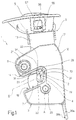
- Figure 1 shows, in a side view, a device for securing a seat back to a body of a motor vehicle; and
- Figures 2 and 3 show, in a side view and with parts removed for clarity, the securing device of Figure 1, in two different operating conditions.
- With reference to Figures 1 to 3, the number 1 indicates in a general way a device for securing a back of a rear seat (known and not illustrated) to a body of a motor vehicle (not illustrated). The seat back is conveniently divided into two independent portions secured together releasably in the raised operating position by means of a fixing pin.
- The device 1 comprises a
pin 2 fixed to the body of the motor vehicle and shown schematically in broken lines in Figure 2, anattachment mechanism 3 carried on the seat back and capable of being coupled to acylindrical portion 4 of thepin 2 in a direction D of relative coupling to secur the seat back releasably to the body, and anoperating lever 5, of a known type, which can be operated manually to release theattachment mechanism 3 from thepin 2. - The
attachment mechanism 3 essentially comprises a supportingframe 6 fixed to the seat back, and afork 7 and aretainer 8 hinged to theframe 6. - In particular, the
frame 6 is formed by a box-shaped body 10 made from sheet material, creating acompartment 11 for housing thefork 7 and theretainer 8, and having a thickness which is small with respect to the other dimensions, and by ashell body 12, preferably made from plastic material, joined to anend extension 13 of the box-shaped body 10 and housing theoperating lever 5. - In the position in which it is fitted to the seat back, the
shell body 12 is located vertically above the box-shaped body 10. - In greater detail, the box-shaped body 10 comprises a
base plate 15 made from plastic material and having an approximately trapezoidal profile, from whose outer perimeter there extends a lateral projectingedge 16 delimiting, together with theplate 15, thecompartment 11. The box-shaped body 10 additionally comprises ametal cover plate 17 of thecompartment 11, located opposite and parallel to theplate 15. Theextension 13 is of essentially parallelepipedal shape and extends integrally with, and projects from, an upper end portion of theedge 16. - The box-shaped body 10 includes a lateral C-
shaped seat 18 formed in theplate 15, communicating with thecompartment 11 and capable of being engaged, with a degree of play, by theportion 4 of thepin 2 during the coupling of the latter to theattachment mechanism 3. Conveniently, theplate 17 has a lateral recess 19 whose shape matches that of theseat 18. Theedge 16 is also interrupted in the area of theseat 18 to permit communication between theseat 18 and thecompartment 11. - To permit the engagement and disengagement of the
portion 4 of thepin 2, theseat 18 has anentry aperture 14 facing in the direction D. - The box-shaped body 10 is also provided with a damping element or
buffer 29, made from relatively yielding material, typically rubber, fixed on aninner edge 28 of theseat 18 opposite theentry aperture 14, extending transversely with respect to the direction D and forming a stop for theportion 4 of thepin 2 during the coupling of thepin 2 to theattachment mechanism 3. - The
fork 7 and theretainer 8 are hinged, respectively, aboutpivots plates compartment 11 between theaforesaid plates plates - With particular reference to Figures 2 and 3, the
fork 7 consists of a shaped metal plate, is hinged in an intermediate portion to thepivot 20 and has a peripheral C-shaped seat 22 capable of receiving theportion 4 of thepin 2 and delimited laterally by a pair ofteeth - The
fork 7 is rotatable about the axis A of thepivot 20 between an open position and a position of attachment to theportion 4 of thepin 2. - In the open position (Figure 2), the
seat 22 has anentry aperture 34 essentially facing in the direction D in a similar way to theaperture 14 of theseat 18 to pemit the engagement and disengagement of theportion 4 of thepin 2; in the attachment position (Figures 1 and 3), theportion 4 of thepin 2 is locked within theseats fixing compartment 32 delimited, on one side, by thedamping element 29 and, on the opposite side, by thetooth 23, which intercepts theseat 18. - Advantageously, the
fixing compartment 32 has a cross section which decreases towards theentry aperture 34 of theseat 22 of thefork 7, and which forms an interference fit with theportion 4 of thepin 2. Thus theportion 4 of thepin 2 can be locked within thefixing compartment 32 in any position, and in particular at any distance from the bottom of theseat 22. - Preferably, the
fixing compartment 32 is delimited by a pair of essentiallyflat stop surfaces damping element 29 and by thetooth 23 of thefork 7, and converging towards each other towards theentry aperture 34 of theseat 22. - The
fork 7 is loaded in a known way towards the opening position by acompression spring 25, of the cylindrical coil type for example (indicated by a broken line in Figures 2 and 3), which is housed in a curved C-shaped channel 26 formed in theplate 15 and is compressed by apin 27 projecting from thefork 7 and coupled slidably within thechannel 26. More precisely, the open position is determined by the contact between a portion of the peripheral edge of thefork 7 adjacent to thetooth 23 and a portion of theedge 16 of the box-shaped body 10 adjacent to theseat 18. - In detail, in the open position, the
tooth 24 of thefork 7 projects partially through theseat 18 and the recess 19 of the box-shaped body 10 in such a way that it intercepts theportion 4 of thepin 2 during the securing of the seat back to the body, and receives, in the impact with theportion 4, a thrust action tending to rotate thefork 7 about the axis A against the action of thespring 25. - Conveniently, the
fork 7 is covered externally with a shell of plastic material, from which the free end of thetooth 23 projects. - Finally, the peripheral edge of the
fork 7 has, in a position adjacent to thetooth 24, aprotuberance 33 having a convex curved profile, whose function will be explained subsequently. - The
retainer 8 consists of an elongate plate coplanar with thefork 7 and made from metal. Theretainer 8 is positioned at one side of thefork 7 and is loaded in a known way towards the latter by aspring 35 wound around thepivot 21 and having a first end portion bent around a stud on theretainer 8 and a second end portion positioned in contact with theedge 16 of the box-shaped body 10. More precisely, in the position in which the securing device 1 is fitted on the back of the rear seat of the motor vehicle, theretainer 8 is located above thefork 7 in a position between thefork 7 and theoperating lever 5. - The
retainer 8 comprises afirst end portion 40 adjacent to theseat 18 and hinged on thepivot 21, anintermediate portion 41 connected to theoperating lever 5 by means of alink 42, and asecond end portion 43 bent in an L-shape towards thefork 7 and coupled in a known way by means of correspondingflexible cable transmissions - The
retainer 8 can releasably lock thefork 7 in the attachment position, by forming with itsshoulder 44, positioned in the proximity of theend portion 40, a stop for the free end of the tooth 23 (Figure 3). - According to an important aspect of the present invention, the
attachment mechanism 3 comprises alever locking element 45, which can be coupled releasably to theend portion 43 of theretainer 8 to keep theretainer 8 in a position of separation from thefork 7 against the action of the spring 35 (Figure 2), and which can be disengaged from theretainer 8 by the displacement of thefork 7 in the attachment position (Figure 3). - In particular, the
locking element 45 consists of a single-leaf spring, extending essentially in a vertical direction which is transverse with respect to the direction D, and positioned at the side of thefork 7 where theend portion 43 of theretainer 8 is located. Thelocking element 45 has aend portion 46 bent in a U-shape around astud 47 projecting from theplate 15 of the box-shaped body 10, and trapped between thestud 47 and theedge 16 in such a way as to form anelastic hinge 48. - The
locking element 45 is pre-loaded towards thefork 7 and theretainer 8 in such a way that, in the absence of external actions, its free C-shaped end portion 49, opposite theend portion 46, tends to become engaged in aperipheral recess 50 of theretainer 8, thus defining a first operating position of thelocking element 45. In particular, therecess 50 is essentially L-shaped, is formed in theend portion 43 of theretainer 8, and faces theedge 16. - During the rotation of the
fork 7 about the axis A towards the attachment position, theprotuberance 33 is able to interact with an intermediate portion 51 of thelocking element 45, thus causing thelocking element 45 to rotate about thehinge 48 towards a second operating position, in which theend portion 49 is rotated towards theedge 16 and is disengaged from therecess 50 of theretainer 8. - The
operating lever 5 is hinged to corresponding lateral walls of theshell body 12 about an axis C parallel to the axes A and B; theoperating lever 5 has an integrallateral tongue 53 provided with anelongate slot 54 extending essentially in a vertical direction and engaged slidably by anend stud 55 of thelink 42. - The
stud 55 of thelink 42 is also fitted slidably within a further horizontalrectilinear slot 56 formed in aplate 57 fitted so that it can slide vertically through a slot of theshell body 12. Theoperating lever 5 is loaded by a corresponding spring (of a known type and not illustrated) into a rest position, in which it is housed completely within theshell body 12, and can be moved manually about the axis C towards an open position in which it projects outside theshell body 12 and, by means of thelink 42, causes theretainer 8 to be disengaged from thefork 7. Theplate 57 can be moved between a lowered position, corresponding to the attachment position of thefork 7, in which it is completely housed within theshell body 12, and a raised position, corresponding to the open position of thefork 7, in which it projects partially from theshell body 12. - The
plate 57 is moved from the lowered position to the raised position by the rotation of theoperating lever 5 from the rest position to the opening position, while the opposite movement is generated by the rotation of theretainer 8 about the axis B following the impact of thepin 2 on thefork 7 which brings the latter to the attachment position. - The
plate 57 provides a visual indication of the condition of securing the rear seat back to the body of the motor vehicle. - The operation of the securing device 1 is described from an initial configuration of disengagement of the rear seat back from the body of the motor vehicle. In this configuration (Figure 2), the
fork 7 is in the open position, theportion 4 of thepin 2 is disengaged from theseats retainer 8 is retained in the position of separation from thefork 7 as a result of the engagement of theend portion 49 of thelocking element 45 in therecess 50, and theplate 57 is held in the raised position by theretainer 8 and thelink 42. Additionally, by means of theflexible cable transmission 39b, theretainer 8 keeps the fixing pin of the two portions of seat back disengaged from one of these portions. - By rotating the seat back to its raised position for use, an impact is caused in the direction D between the
portion 4 of thepin 2 and thetooth 24 of thefork 7, which rotates in the clockwise direction from the open position of Figure 2 towards the attachment position of Figures 1 and 3. - During the rotation of the
fork 7, theprotuberance 33 interacts with thelocking element 45, causing it to rotate about thehinge 48 towards theedge 16 and consequently causing theend portion 49 of thelocking element 45 to be disengaged from therecess 50 of theretainer 8. Under the action of thespring 35, theretainer 8 therefore rotates about the axis B towards thefork 7, thus pulling theplate 57 into the lowered position by means of thelink 42. At the same time, thetooth 23 of thefork 7 snaps into a position where it bears on theshoulder 44 and is locked by the latter in the attachment position. Theportion 4 of thepin 2 therefore remains enclosed within theseats surface 30 of thetooth 23 and thesurface 31 of the dampingelement 29, thus forming a configuration in which the seat back is secured to the body. - To return to the initial configuration of disengagement, it is simply necessary to move the operating
lever 5, rotating it in the clockwise direction according to Figures 2 and 3 towards the open position. Because of the essentially orthogonal arrangement of the directions of extension of theslots plate 57 is moved towards its raised position together with thestud 55 of thelink 42. At the same time, theretainer 8 is rotated in the anti-clockwise direction (with reference to the attached figures) about the axis B, thus releasing thefork 7. - In particular, the
tooth 23 is disengaged from theshoulder 44 and, under the thrust action of thespring 25, thefork 7 rotates in the anti-clockwise direction towards the open position. During this movement, theprotuberance 33 is separated from the lockingelement 45, which can therefore rotate towards thefork 7 until itsend portion 49 engages in therecess 50 of theretainer 8, thus locking theretainer 8 in the position of separation from thefork 7. - When the open position of the
fork 7 has been reached, theportion 4 of thepin 2 can be disengaged from theseat 22 of thefork 7. - An examination of the characteristics of the securing device 1 made according to the present invention clearly reveals the advantages which it provides.
- In particular, owing to the arrangement of the locking
element 45, which holds theretainer 8 in a position of separation from thefork 7 in the stages of securing the seat back to the body and releasing it therefrom, thefork 7 can move freely without friction between its open and attachement positions. The risk that thefork 7, following the release of theretainer 8, may be placed in a position other than the open position, with the possible blocking or breaking of theattachment mechanism 3 in the next stage of securing the seat back to the body, is therefore avoided. - Finally, it is clear that modifications and variations can be made to the securing device 1 without departure from the scope of protection of the present invention.
- In particular, the
attachment mechanism 3 could be fixed to the body of the motor vehicle and thepin 2 could be fixed to the seat back.
Claims (8)
- Device (1) for securing a seat back to a body of a motor vehicle, comprising at least one pin (2) carried on either the seat back or the body, and an attachment mechanism (3) carried on another of either the seat back or the body and capable of interacting with the said pin (2), the said attachment mechanism (3) comprising:characterized in that the said attachment mechanism (3) comprises releasable locking means (45), which interact with the said retainer (8) to keep it in a position of separation from the said fork (7), and which can be selectively disabled by the movement of the fork (7) into the said attachment position.a supporting body (6);a fork (7) hinged to the said supporting body (6), forming an engagement seat (22) for the said pin (2) and loaded by first elastic means (25) towards an open position, in which the engagement of the said pin (2) with the said seat (22) and its disengagement therefrom are permitted; anda retainer (8) hinged to the said supporting body (6), loaded by second elastic means (35) towards the said fork (7) and capable of being snapped on to the fork (7) to lock it releasably in an attachment position, in which the said pin (2) is coupled to the said seat (22) ;
- Device according to Claim 1, characterized in that the said locking means comprise a lever element (45) movable between a first operating position, in which it is coupled releasably to the said retainer (8) and keeps it in the said position of separation from the said fork (7), and a second operating position, in which the lever element (45) is released from the said retainer (8).
- Device according to Claim 2, characterized in that the said lever element (45) is located at one side of the said fork (7) and is loaded towards the said first operating position of coupling to the said retainer (8), and in that the said fork (7) has an interaction portion (33) capable of exerting a thrust on the said lever element (45) to uncouple it from the said retainer (8) during the movement of the fork (7) towards the said attachment position.
- Device according to Claim 3, characterized in that the said interaction portion is formed by a protuberance (33) of the peripheral edge of the said fork (7).
- Device according to any one of Claims 2 to 4, characterized in that the said lever element (45) has a first end portion (46) secured in the form of a hinge to the said supporting body (6) and a second free end portion (49) which can be coupled releasably to an end recess (50) of the said retainer (8).
- Device according to Claim 5, characterized in that the said recess (50) is essentially L-shaped.
- Device according to any one of Claims 2 to 6, characterized in that the said lever element (45) consists of a leaf spring.
- Device according to Claim 7, characterized in that the said first end portion (46) of the said lever element (45) is essentially U-shaped, is wound around a stud (47) of the said supporting body (6) and is trapped between the stud (47) and a retaining portion (16) of the said supporting body (6).
Applications Claiming Priority (2)
| Application Number | Priority Date | Filing Date | Title |
|---|---|---|---|
| IT2000TO000521A IT1320387B1 (en) | 2000-06-02 | 2000-06-02 | BINDING DEVICE OF A SEAT BACKREST TO A BODY OF A VEHICLE. |
| ITTO000521 | 2000-06-02 |
Publications (2)
| Publication Number | Publication Date |
|---|---|
| EP1160121A1 true EP1160121A1 (en) | 2001-12-05 |
| EP1160121B1 EP1160121B1 (en) | 2004-10-27 |
Family
ID=11457778
Family Applications (1)
| Application Number | Title | Priority Date | Filing Date |
|---|---|---|---|
| EP01113307A Expired - Lifetime EP1160121B1 (en) | 2000-06-02 | 2001-05-31 | Device for securing a seat back to a body of a motor vehicle |
Country Status (6)
| Country | Link |
|---|---|
| EP (1) | EP1160121B1 (en) |
| BR (1) | BR0102953A (en) |
| DE (1) | DE60106673T2 (en) |
| ES (1) | ES2231344T3 (en) |
| IT (1) | IT1320387B1 (en) |
| PL (1) | PL201372B1 (en) |
Cited By (5)
| Publication number | Priority date | Publication date | Assignee | Title |
|---|---|---|---|---|
| EP1586484A2 (en) * | 2004-04-17 | 2005-10-19 | KEIPER GmbH & Co. KG | Locking device for a vehicle, particularly for a vehicle seat. |
| DE102004031266A1 (en) * | 2004-06-29 | 2006-01-19 | Bayerische Motoren Werke Ag | Lock with turning latch has hole for locking pin fixed between two limbs which close latch, spring-loaded link and spring piece to load locking pin against side of hole, narrow it and tension it when pushed into hole |
| WO2006084898A3 (en) * | 2005-02-11 | 2006-11-23 | Johnson Controls Gmbh | Device for locking and unlocking especially the backrest of an automotive seat, comprising signaling means, and automotive seat comprising such a device |
| WO2006128531A1 (en) | 2005-05-27 | 2006-12-07 | Johnson Controls Gmbh | Vehicle seat, in particular seat bench for a motor vehicle |
| US7188872B2 (en) * | 2000-03-23 | 2007-03-13 | Meritor Light Vehicle Systems (Uk) Limited | Latch mechanism |
Families Citing this family (1)
| Publication number | Priority date | Publication date | Assignee | Title |
|---|---|---|---|---|
| DE102005041744A1 (en) * | 2005-09-02 | 2007-03-08 | Bayerische Motoren Werke Ag | Safety device for e.g. police vehicle, has safety part preventing movement of unlocking and locking units and either loaded into locking position or retained in locking position by using retaining device that comprises clamping walls |
Citations (5)
| Publication number | Priority date | Publication date | Assignee | Title |
|---|---|---|---|---|
| DE1801154A1 (en) * | 1968-10-04 | 1970-04-23 | Saseb S A | Unlockable snap lock, especially for the lid of the engine and luggage compartment on motor vehicles |
| FR2306102A1 (en) * | 1975-04-04 | 1976-10-29 | Keiper Kg | Seat mechanism for motor vehicles - has locking system to prevent seat pivoting forward on heavy braking |
| GB2231617A (en) * | 1989-04-28 | 1990-11-21 | Keiper Recaro Gmbh Co | Vehicle seat tilt lock mechanism |
| US5722727A (en) * | 1995-08-23 | 1998-03-03 | Keiper Recaro Gmbh & Co. | Articulated fitting for vehicle seats, in particular motor vehicle seats |
| WO1999002365A1 (en) * | 1997-07-07 | 1999-01-21 | Atoma International Inc. | Removable vehicle seat assembly |
-
2000
- 2000-06-02 IT IT2000TO000521A patent/IT1320387B1/en active
-
2001
- 2001-05-31 ES ES01113307T patent/ES2231344T3/en not_active Expired - Lifetime
- 2001-05-31 DE DE60106673T patent/DE60106673T2/en not_active Expired - Fee Related
- 2001-05-31 BR BR0102953-3A patent/BR0102953A/en not_active Application Discontinuation
- 2001-05-31 EP EP01113307A patent/EP1160121B1/en not_active Expired - Lifetime
- 2001-06-01 PL PL347844A patent/PL201372B1/en not_active IP Right Cessation
Patent Citations (5)
| Publication number | Priority date | Publication date | Assignee | Title |
|---|---|---|---|---|
| DE1801154A1 (en) * | 1968-10-04 | 1970-04-23 | Saseb S A | Unlockable snap lock, especially for the lid of the engine and luggage compartment on motor vehicles |
| FR2306102A1 (en) * | 1975-04-04 | 1976-10-29 | Keiper Kg | Seat mechanism for motor vehicles - has locking system to prevent seat pivoting forward on heavy braking |
| GB2231617A (en) * | 1989-04-28 | 1990-11-21 | Keiper Recaro Gmbh Co | Vehicle seat tilt lock mechanism |
| US5722727A (en) * | 1995-08-23 | 1998-03-03 | Keiper Recaro Gmbh & Co. | Articulated fitting for vehicle seats, in particular motor vehicle seats |
| WO1999002365A1 (en) * | 1997-07-07 | 1999-01-21 | Atoma International Inc. | Removable vehicle seat assembly |
Cited By (10)
| Publication number | Priority date | Publication date | Assignee | Title |
|---|---|---|---|---|
| US7188872B2 (en) * | 2000-03-23 | 2007-03-13 | Meritor Light Vehicle Systems (Uk) Limited | Latch mechanism |
| EP1586484A2 (en) * | 2004-04-17 | 2005-10-19 | KEIPER GmbH & Co. KG | Locking device for a vehicle, particularly for a vehicle seat. |
| EP1586484A3 (en) * | 2004-04-17 | 2007-01-24 | KEIPER GmbH & Co. KG | Locking device for a vehicle, particularly for a vehicle seat |
| DE102004031266A1 (en) * | 2004-06-29 | 2006-01-19 | Bayerische Motoren Werke Ag | Lock with turning latch has hole for locking pin fixed between two limbs which close latch, spring-loaded link and spring piece to load locking pin against side of hole, narrow it and tension it when pushed into hole |
| WO2006084898A3 (en) * | 2005-02-11 | 2006-11-23 | Johnson Controls Gmbh | Device for locking and unlocking especially the backrest of an automotive seat, comprising signaling means, and automotive seat comprising such a device |
| EP2335970A1 (en) * | 2005-02-11 | 2011-06-22 | Johnson Controls GmbH | Device for locking and unlocking especially the backrest of a seat, especially of an automotive vehicle |
| EP2335968A1 (en) * | 2005-02-11 | 2011-06-22 | Johnson Controls GmbH | Device for locking and unlocking especially the backrest of a seat, especially of an automotive vehicle |
| EP2335969A1 (en) * | 2005-02-11 | 2011-06-22 | Johnson Controls GmbH | Device for locking and unlocking especially the backrest of a seat, especially of an automotive vehicle |
| US8882161B2 (en) | 2005-02-11 | 2014-11-11 | Johnson Controls Gmbh | Locking device with signal structure |
| WO2006128531A1 (en) | 2005-05-27 | 2006-12-07 | Johnson Controls Gmbh | Vehicle seat, in particular seat bench for a motor vehicle |
Also Published As
| Publication number | Publication date |
|---|---|
| IT1320387B1 (en) | 2003-11-26 |
| ES2231344T3 (en) | 2005-05-16 |
| ITTO20000521A0 (en) | 2000-06-02 |
| DE60106673T2 (en) | 2006-02-09 |
| ITTO20000521A1 (en) | 2001-12-02 |
| EP1160121B1 (en) | 2004-10-27 |
| PL347844A1 (en) | 2001-12-03 |
| PL201372B1 (en) | 2009-04-30 |
| DE60106673D1 (en) | 2004-12-02 |
| BR0102953A (en) | 2002-02-13 |
Similar Documents
| Publication | Publication Date | Title |
|---|---|---|
| US9810005B2 (en) | Vehicle door handle comprising an inertial mass | |
| US4527317A (en) | Buckle for a safety belt | |
| JPH0626167Y2 (en) | Latch buckle for seat belt | |
| EP3406831A1 (en) | Vehicular latch with double pawl arrangement | |
| JPS6335611Y2 (en) | ||
| JPS6343933Y2 (en) | ||
| EP1160121B1 (en) | Device for securing a seat back to a body of a motor vehicle | |
| US5915633A (en) | Buckle for safety belts | |
| JP2007503542A (en) | Handle assembly with double latch | |
| US8882161B2 (en) | Locking device with signal structure | |
| KR100512828B1 (en) | Seat sliding apparatus | |
| CN113653414B (en) | Sliding door locking means and vehicle | |
| EP0061465B1 (en) | Seat belt retractor assembly with post emergency spool release | |
| US4702494A (en) | Device for adjusting the position of a strap return element of a safety belt | |
| EP0719506B1 (en) | Buckle for seat belt device | |
| US20080040905A1 (en) | Seat belt buckle for use with pretensioner | |
| EP0411738A2 (en) | Seat belt retractor | |
| JP3736858B2 (en) | buckle | |
| US4490892A (en) | Buckle device | |
| HU202154B (en) | Lock-gear for the belt structure of parachute | |
| EP1033463A2 (en) | A disengageable door stop for vehicles | |
| CN113330176B (en) | Electric vehicle latch with emergency release | |
| JP2981440B2 (en) | Adjustment device for bending fixture | |
| JPS6030116Y2 (en) | Buckle device | |
| EP1374714A2 (en) | Buckle |
Legal Events
| Date | Code | Title | Description |
|---|---|---|---|
| PUAI | Public reference made under article 153(3) epc to a published international application that has entered the european phase |
Free format text: ORIGINAL CODE: 0009012 |
|
| AK | Designated contracting states |
Kind code of ref document: A1 Designated state(s): AT BE CH CY DE DK ES FI FR GB GR IE IT LI LU MC NL PT SE TR Kind code of ref document: A1 Designated state(s): DE ES FR GB IT |
|
| AX | Request for extension of the european patent |
Free format text: AL;LT;LV;MK;RO;SI |
|
| RAP1 | Party data changed (applicant data changed or rights of an application transferred) |
Owner name: INTIER AUTOMOTIVE CLOSURES S.P.A |
|
| 17P | Request for examination filed |
Effective date: 20020603 |
|
| AKX | Designation fees paid |
Free format text: DE ES FR GB IT |
|
| 17Q | First examination report despatched |
Effective date: 20030804 |
|
| GRAP | Despatch of communication of intention to grant a patent |
Free format text: ORIGINAL CODE: EPIDOSNIGR1 |
|
| RAP1 | Party data changed (applicant data changed or rights of an application transferred) |
Owner name: INTIER AUTOMOTIVE EYBL (GERMANY) GMBH |
|
| GRAS | Grant fee paid |
Free format text: ORIGINAL CODE: EPIDOSNIGR3 |
|
| GRAA | (expected) grant |
Free format text: ORIGINAL CODE: 0009210 |
|
| AK | Designated contracting states |
Kind code of ref document: B1 Designated state(s): DE ES FR GB IT |
|
| REG | Reference to a national code |
Ref country code: GB Ref legal event code: FG4D |
|
| REG | Reference to a national code |
Ref country code: IE Ref legal event code: FG4D |
|
| REF | Corresponds to: |
Ref document number: 60106673 Country of ref document: DE Date of ref document: 20041202 Kind code of ref document: P |
|
| REG | Reference to a national code |
Ref country code: ES Ref legal event code: FG2A Ref document number: 2231344 Country of ref document: ES Kind code of ref document: T3 |
|
| PLBE | No opposition filed within time limit |
Free format text: ORIGINAL CODE: 0009261 |
|
| STAA | Information on the status of an ep patent application or granted ep patent |
Free format text: STATUS: NO OPPOSITION FILED WITHIN TIME LIMIT |
|
| ET | Fr: translation filed | ||
| 26N | No opposition filed |
Effective date: 20050728 |
|
| PGFP | Annual fee paid to national office [announced via postgrant information from national office to epo] |
Ref country code: ES Payment date: 20090605 Year of fee payment: 9 |
|
| PGFP | Annual fee paid to national office [announced via postgrant information from national office to epo] |
Ref country code: DE Payment date: 20090529 Year of fee payment: 9 Ref country code: FR Payment date: 20090515 Year of fee payment: 9 Ref country code: IT Payment date: 20090521 Year of fee payment: 9 |
|
| PGFP | Annual fee paid to national office [announced via postgrant information from national office to epo] |
Ref country code: GB Payment date: 20090527 Year of fee payment: 9 |
|
| GBPC | Gb: european patent ceased through non-payment of renewal fee |
Effective date: 20100531 |
|
| REG | Reference to a national code |
Ref country code: FR Ref legal event code: ST Effective date: 20110131 |
|
| PG25 | Lapsed in a contracting state [announced via postgrant information from national office to epo] |
Ref country code: IT Free format text: LAPSE BECAUSE OF NON-PAYMENT OF DUE FEES Effective date: 20100531 |
|
| PG25 | Lapsed in a contracting state [announced via postgrant information from national office to epo] |
Ref country code: DE Free format text: LAPSE BECAUSE OF NON-PAYMENT OF DUE FEES Effective date: 20101201 |
|
| PG25 | Lapsed in a contracting state [announced via postgrant information from national office to epo] |
Ref country code: FR Free format text: LAPSE BECAUSE OF NON-PAYMENT OF DUE FEES Effective date: 20100531 |
|
| REG | Reference to a national code |
Ref country code: ES Ref legal event code: FD2A Effective date: 20110714 |
|
| PG25 | Lapsed in a contracting state [announced via postgrant information from national office to epo] |
Ref country code: ES Free format text: LAPSE BECAUSE OF NON-PAYMENT OF DUE FEES Effective date: 20110704 Ref country code: GB Free format text: LAPSE BECAUSE OF NON-PAYMENT OF DUE FEES Effective date: 20100531 |
|
| PG25 | Lapsed in a contracting state [announced via postgrant information from national office to epo] |
Ref country code: ES Free format text: LAPSE BECAUSE OF NON-PAYMENT OF DUE FEES Effective date: 20100601 |