EP1160115A2 - Antivibration device for the clutch pedal of a motor vehicle - Google Patents
Antivibration device for the clutch pedal of a motor vehicle Download PDFInfo
- Publication number
- EP1160115A2 EP1160115A2 EP00127676A EP00127676A EP1160115A2 EP 1160115 A2 EP1160115 A2 EP 1160115A2 EP 00127676 A EP00127676 A EP 00127676A EP 00127676 A EP00127676 A EP 00127676A EP 1160115 A2 EP1160115 A2 EP 1160115A2
- Authority
- EP
- European Patent Office
- Prior art keywords
- motor vehicle
- pedal
- push rod
- clutch pedal
- clutch
- Prior art date
- Legal status (The legal status is an assumption and is not a legal conclusion. Google has not performed a legal analysis and makes no representation as to the accuracy of the status listed.)
- Granted
Links
Images

Classifications
-
- G—PHYSICS
- G05—CONTROLLING; REGULATING
- G05G—CONTROL DEVICES OR SYSTEMS INSOFAR AS CHARACTERISED BY MECHANICAL FEATURES ONLY
- G05G1/00—Controlling members, e.g. knobs or handles; Assemblies or arrangements thereof; Indicating position of controlling members
- G05G1/30—Controlling members actuated by foot
-
- B—PERFORMING OPERATIONS; TRANSPORTING
- B60—VEHICLES IN GENERAL
- B60K—ARRANGEMENT OR MOUNTING OF PROPULSION UNITS OR OF TRANSMISSIONS IN VEHICLES; ARRANGEMENT OR MOUNTING OF PLURAL DIVERSE PRIME-MOVERS IN VEHICLES; AUXILIARY DRIVES FOR VEHICLES; INSTRUMENTATION OR DASHBOARDS FOR VEHICLES; ARRANGEMENTS IN CONNECTION WITH COOLING, AIR INTAKE, GAS EXHAUST OR FUEL SUPPLY OF PROPULSION UNITS IN VEHICLES
- B60K23/00—Arrangement or mounting of control devices for vehicle transmissions, or parts thereof, not otherwise provided for
- B60K23/02—Arrangement or mounting of control devices for vehicle transmissions, or parts thereof, not otherwise provided for for main transmission clutches
-
- B—PERFORMING OPERATIONS; TRANSPORTING
- B60—VEHICLES IN GENERAL
- B60T—VEHICLE BRAKE CONTROL SYSTEMS OR PARTS THEREOF; BRAKE CONTROL SYSTEMS OR PARTS THEREOF, IN GENERAL; ARRANGEMENT OF BRAKING ELEMENTS ON VEHICLES IN GENERAL; PORTABLE DEVICES FOR PREVENTING UNWANTED MOVEMENT OF VEHICLES; VEHICLE MODIFICATIONS TO FACILITATE COOLING OF BRAKES
- B60T7/00—Brake-action initiating means
- B60T7/02—Brake-action initiating means for personal initiation
- B60T7/04—Brake-action initiating means for personal initiation foot actuated
- B60T7/06—Disposition of pedal
-
- G—PHYSICS
- G05—CONTROLLING; REGULATING
- G05G—CONTROL DEVICES OR SYSTEMS INSOFAR AS CHARACTERISED BY MECHANICAL FEATURES ONLY
- G05G1/00—Controlling members, e.g. knobs or handles; Assemblies or arrangements thereof; Indicating position of controlling members
- G05G1/30—Controlling members actuated by foot
- G05G1/46—Means, e.g. links, for connecting the pedal to the controlled unit
Definitions
- the present invention refers to an anti-vibration and anti-noise device for the clutch pedal of a motor vehicle, where the clutch is controlled by means of a push rod, operated by the pedal itself.
- reference number 1 indicates a clutch pedal of a motor vehicle, presenting one hand hinged at 2 and being provided with a support 3 for the foot at the other end.
- the pedal 1 presents a seat 5 for the push rod 6 of an hydraulic control for the clutch (not shown).
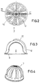
- an elastic cup-shaped bush 7 Inside the seat 5 there is, according to the invention, an elastic cup-shaped bush 7.
- the bush advantageously consists of a metal part 9, which is in contact with the push rod 6, and of a part 10 made of elastic material, preferably rubber vulcanised on it, which rests on the seat 5 in the pedal 1.
- the elastic part 10 presents advantageous ribs 12 on its external surface, the wideness and dimensions of the ribs being studied in order to be in accordance to the frequencies of the vibrations coming from the push rod, so that the vibrations are almost completely nullified, while the noise that could be transmitted inside the passenger compartment is reduced as well.
- the bushes shall be adapted to the different types of motor vehicle on which they are used. This is possible by means of varying the shape and wideness of said ribs 12 until the desired effect is achieved.
Landscapes
- Engineering & Computer Science (AREA)
- General Physics & Mathematics (AREA)
- Transportation (AREA)
- Mechanical Engineering (AREA)
- Physics & Mathematics (AREA)
- Automation & Control Theory (AREA)
- Combustion & Propulsion (AREA)
- Chemical & Material Sciences (AREA)
- Arrangement And Mounting Of Devices That Control Transmission Of Motive Force (AREA)
- Vibration Prevention Devices (AREA)
- Mechanical Operated Clutches (AREA)
- Mechanical Control Devices (AREA)
- Hydraulic Clutches, Magnetic Clutches, Fluid Clutches, And Fluid Joints (AREA)
Abstract

Description
Claims (4)
- A vibration-dampening device for the clutch pedal (1) of a motor vehicle, said pedal being provided with a seat (5) adapted to house the push rod (6) of a piston which is part of the hydraulic control of the clutch, characterised in that it consists of an elastic cup-shaped bush (7), located inside said seat, between the pedal and the push rod.
- Device as claimed in claim 1, characterised in that the cup shaped bush (7) consists of an inner metal part (9) and of an external part made of elastic material (10).
- Device as claimed in claim 2, characterised in that the elastic material (10) presents ribs (12) on its external surface.
- Device as claimed in claim 3 characterised in that the shape of the ribs varies as a function of the vibrations to be absorbed.
Applications Claiming Priority (2)
| Application Number | Priority Date | Filing Date | Title |
|---|---|---|---|
| IT2000TO000094 IT249529Y1 (en) | 2000-06-02 | 2000-06-02 | ANTI-VIBRATION DEVICE FOR THE CLUTCH PEDAL OF A VEHICLE. |
| ITTO000094 | 2000-06-02 |
Publications (3)
| Publication Number | Publication Date |
|---|---|
| EP1160115A2 true EP1160115A2 (en) | 2001-12-05 |
| EP1160115A3 EP1160115A3 (en) | 2002-11-06 |
| EP1160115B1 EP1160115B1 (en) | 2004-09-01 |
Family
ID=11457347
Family Applications (1)
| Application Number | Title | Priority Date | Filing Date |
|---|---|---|---|
| EP20000127676 Expired - Lifetime EP1160115B1 (en) | 2000-06-02 | 2000-12-18 | Antivibration device for the clutch pedal of a motor vehicle |
Country Status (4)
| Country | Link |
|---|---|
| EP (1) | EP1160115B1 (en) |
| BR (1) | BR0100243B1 (en) |
| DE (1) | DE60013415T2 (en) |
| IT (1) | IT249529Y1 (en) |
Cited By (2)
| Publication number | Priority date | Publication date | Assignee | Title |
|---|---|---|---|---|
| FR2842318A1 (en) * | 2002-07-09 | 2004-01-16 | Volkswagen Ag | PEDAL ASSEMBLY AND ASSEMBLY METHOD THEREFOR |
| WO2006066542A3 (en) * | 2004-12-22 | 2006-08-24 | Luk Lamellen & Kupplungsbau | Articulated connection for a release device |
Families Citing this family (1)
| Publication number | Priority date | Publication date | Assignee | Title |
|---|---|---|---|---|
| CN112918248B (en) * | 2021-01-29 | 2022-07-26 | 浙江吉利控股集团有限公司 | Automobile crumple type pedal assembly |
Family Cites Families (3)
| Publication number | Priority date | Publication date | Assignee | Title |
|---|---|---|---|---|
| DE7918243U1 (en) * | 1980-01-03 | Boge Gmbh, 5208 Eitorf | Noise isolation bearings | |
| DE19542071C2 (en) * | 1995-11-11 | 2000-03-30 | Trw Fahrwerksyst Gmbh & Co | Ball joint |
| IT1293682B1 (en) * | 1997-08-07 | 1999-03-08 | Siv S P A | DEVICE FOR ATTACHING THE BRAKE PEDAL OF A MOTOR VEHICLE TO THE BRAKE SERVO TIP. |
-
2000
- 2000-06-02 IT IT2000TO000094 patent/IT249529Y1/en active
- 2000-12-18 DE DE2000613415 patent/DE60013415T2/en not_active Expired - Lifetime
- 2000-12-18 EP EP20000127676 patent/EP1160115B1/en not_active Expired - Lifetime
-
2001
- 2001-02-01 BR BR0100243A patent/BR0100243B1/en not_active IP Right Cessation
Cited By (4)
| Publication number | Priority date | Publication date | Assignee | Title |
|---|---|---|---|---|
| FR2842318A1 (en) * | 2002-07-09 | 2004-01-16 | Volkswagen Ag | PEDAL ASSEMBLY AND ASSEMBLY METHOD THEREFOR |
| DE10230855A1 (en) * | 2002-07-09 | 2004-01-22 | Volkswagen Ag | Pedal arrangement and assembly method therefor |
| DE10230855B4 (en) * | 2002-07-09 | 2011-11-17 | Volkswagen Ag | Pedal assembly and mounting method for this |
| WO2006066542A3 (en) * | 2004-12-22 | 2006-08-24 | Luk Lamellen & Kupplungsbau | Articulated connection for a release device |
Also Published As
| Publication number | Publication date |
|---|---|
| EP1160115A3 (en) | 2002-11-06 |
| DE60013415T2 (en) | 2005-03-03 |
| ITTO20000094V0 (en) | 2000-06-02 |
| BR0100243B1 (en) | 2009-01-13 |
| IT249529Y1 (en) | 2003-05-19 |
| ITTO20000094U1 (en) | 2001-12-02 |
| DE60013415D1 (en) | 2004-10-07 |
| EP1160115B1 (en) | 2004-09-01 |
| BR0100243A (en) | 2002-02-13 |
Similar Documents
| Publication | Publication Date | Title |
|---|---|---|
| EP0148332B1 (en) | Shift lever | |
| EP2733390B1 (en) | Dampening structure for gear shift cables | |
| CN105383292B (en) | Clutch pedal system and master cylinder for clutch pedal system of vehicle | |
| US5452623A (en) | Noise and vibration damper for a transmission shift lever | |
| JP2006266354A (en) | Vibration isolator | |
| EP1160115B1 (en) | Antivibration device for the clutch pedal of a motor vehicle | |
| US7159486B2 (en) | Joint arrangement for a gear shift mechanism | |
| US9599213B2 (en) | Shift lever assembly with axially offset noise and vibration damper | |
| GB2165020A (en) | Vibration attenuator for a clutch control linkage | |
| KR102341479B1 (en) | Rear Mounting Structure of Powertrain for Automotive | |
| EP1657455B1 (en) | Clutch linkage with vibration isolation and damping | |
| KR100460929B1 (en) | A mounting device of transmission in vehicles | |
| KR100820202B1 (en) | Clutch pedal effort reduction device for vehicle | |
| KR102607627B1 (en) | Rear Mounting Structure of Powertrain for Automotive | |
| KR20040035263A (en) | rear roll stopper transmission mounting bracket for vehicle | |
| KR100483159B1 (en) | preventing vibration structure of clutch pedal for an automobile | |
| KR20030087491A (en) | Vibration Preventive Apparatus of Clutch Pedal | |
| JP4927081B2 (en) | Hydraulic prime mover bearing device | |
| KR200171629Y1 (en) | Clutch cable | |
| KR200166699Y1 (en) | Clutch pedal with anti-vibration structure | |
| JP2004211714A (en) | Anti-vibration device | |
| KR20040018805A (en) | transmission lever for a vehicle | |
| KR970065082A (en) | Anti-vibration device for automobile shift lever | |
| KR20090114160A (en) | Automotive Engine Mounts | |
| KR20080030741A (en) | Clutch pedal vibration reduction device for vehicle |
Legal Events
| Date | Code | Title | Description |
|---|---|---|---|
| PUAI | Public reference made under article 153(3) epc to a published international application that has entered the european phase |
Free format text: ORIGINAL CODE: 0009012 |
|
| AK | Designated contracting states |
Kind code of ref document: A2 Designated state(s): AT BE CH CY DE DK ES FI FR GB GR IE IT LI LU MC NL PT SE TR |
|
| AX | Request for extension of the european patent |
Free format text: AL;LT;LV;MK;RO;SI |
|
| PUAL | Search report despatched |
Free format text: ORIGINAL CODE: 0009013 |
|
| AK | Designated contracting states |
Kind code of ref document: A3 Designated state(s): AT BE CH CY DE DK ES FI FR GB GR IE IT LI LU MC NL PT SE TR |
|
| AX | Request for extension of the european patent |
Free format text: AL;LT;LV;MK;RO;SI |
|
| RIC1 | Information provided on ipc code assigned before grant |
Free format text: 7B 60K 23/02 A, 7B 60T 11/18 B, 7G 05G 1/14 B |
|
| 17P | Request for examination filed |
Effective date: 20021119 |
|
| AKX | Designation fees paid |
Designated state(s): DE FR GB IT |
|
| 17Q | First examination report despatched |
Effective date: 20030821 |
|
| GRAP | Despatch of communication of intention to grant a patent |
Free format text: ORIGINAL CODE: EPIDOSNIGR1 |
|
| GRAS | Grant fee paid |
Free format text: ORIGINAL CODE: EPIDOSNIGR3 |
|
| GRAA | (expected) grant |
Free format text: ORIGINAL CODE: 0009210 |
|
| AK | Designated contracting states |
Kind code of ref document: B1 Designated state(s): DE FR GB IT |
|
| REG | Reference to a national code |
Ref country code: GB Ref legal event code: FG4D |
|
| REG | Reference to a national code |
Ref country code: IE Ref legal event code: FG4D |
|
| REF | Corresponds to: |
Ref document number: 60013415 Country of ref document: DE Date of ref document: 20041007 Kind code of ref document: P |
|
| ET | Fr: translation filed | ||
| PLBE | No opposition filed within time limit |
Free format text: ORIGINAL CODE: 0009261 |
|
| STAA | Information on the status of an ep patent application or granted ep patent |
Free format text: STATUS: NO OPPOSITION FILED WITHIN TIME LIMIT |
|
| 26N | No opposition filed |
Effective date: 20050602 |
|
| EN | Fr: translation not filed | ||
| ET1 | Fr: translation filed ** revision of the translation of the patent or the claims | ||
| REG | Reference to a national code |
Ref country code: FR Ref legal event code: ERR Free format text: BOPI DE PUBLICATION N: 05/35 PAGES: 213 PARTIE DU BULLETIN CONCERNEE: BREVETS EUROPEENS DONT LA TRADUCTION N'A PAS ETE REMISE A I'INPI IL Y A LIEU DE SUPPRIMER: LA MENTION DE LA NON REMISE. LA REMISE DE LA TRADUCTION REVISEE EST PUBLIEE DANS LE PRESENT BOPI. |
|
| REG | Reference to a national code |
Ref country code: FR Ref legal event code: TP |
|
| REG | Reference to a national code |
Ref country code: GB Ref legal event code: 732E |
|
| PGFP | Annual fee paid to national office [announced via postgrant information from national office to epo] |
Ref country code: IT Payment date: 20061231 Year of fee payment: 7 |
|
| REG | Reference to a national code |
Ref country code: GB Ref legal event code: 732E |
|
| REG | Reference to a national code |
Ref country code: FR Ref legal event code: TP |
|
| PG25 | Lapsed in a contracting state [announced via postgrant information from national office to epo] |
Ref country code: IT Free format text: LAPSE BECAUSE OF NON-PAYMENT OF DUE FEES Effective date: 20071218 |
|
| REG | Reference to a national code |
Ref country code: FR Ref legal event code: RN |
|
| REG | Reference to a national code |
Ref country code: FR Ref legal event code: FC |
|
| REG | Reference to a national code |
Ref country code: FR Ref legal event code: PLFP Year of fee payment: 16 |
|
| REG | Reference to a national code |
Ref country code: FR Ref legal event code: PLFP Year of fee payment: 17 |
|
| REG | Reference to a national code |
Ref country code: FR Ref legal event code: PLFP Year of fee payment: 18 |
|
| PGFP | Annual fee paid to national office [announced via postgrant information from national office to epo] |
Ref country code: DE Payment date: 20181126 Year of fee payment: 19 |
|
| PGFP | Annual fee paid to national office [announced via postgrant information from national office to epo] |
Ref country code: GB Payment date: 20181127 Year of fee payment: 19 |
|
| PGFP | Annual fee paid to national office [announced via postgrant information from national office to epo] |
Ref country code: FR Payment date: 20181127 Year of fee payment: 19 |
|
| REG | Reference to a national code |
Ref country code: DE Ref legal event code: R119 Ref document number: 60013415 Country of ref document: DE |
|
| GBPC | Gb: european patent ceased through non-payment of renewal fee |
Effective date: 20191218 |
|
| PG25 | Lapsed in a contracting state [announced via postgrant information from national office to epo] |
Ref country code: DE Free format text: LAPSE BECAUSE OF NON-PAYMENT OF DUE FEES Effective date: 20200701 Ref country code: FR Free format text: LAPSE BECAUSE OF NON-PAYMENT OF DUE FEES Effective date: 20191231 Ref country code: GB Free format text: LAPSE BECAUSE OF NON-PAYMENT OF DUE FEES Effective date: 20191218 |