EP1160104B1 - Trailer coupling - Google Patents
Trailer coupling Download PDFInfo
- Publication number
- EP1160104B1 EP1160104B1 EP00117478A EP00117478A EP1160104B1 EP 1160104 B1 EP1160104 B1 EP 1160104B1 EP 00117478 A EP00117478 A EP 00117478A EP 00117478 A EP00117478 A EP 00117478A EP 1160104 B1 EP1160104 B1 EP 1160104B1
- Authority
- EP
- European Patent Office
- Prior art keywords
- sensor
- trailer
- coupling apparatus
- trailer coupling
- ball
- Prior art date
- Legal status (The legal status is an assumption and is not a legal conclusion. Google has not performed a legal analysis and makes no representation as to the accuracy of the status listed.)
- Expired - Lifetime
Links
Images


Classifications
-
- B—PERFORMING OPERATIONS; TRANSPORTING
- B60—VEHICLES IN GENERAL
- B60D—VEHICLE CONNECTIONS
- B60D1/00—Traction couplings; Hitches; Draw-gear; Towing devices
- B60D1/58—Auxiliary devices
- B60D1/62—Auxiliary devices involving supply lines, electric circuits, or the like
-
- B—PERFORMING OPERATIONS; TRANSPORTING
- B60—VEHICLES IN GENERAL
- B60D—VEHICLE CONNECTIONS
- B60D1/00—Traction couplings; Hitches; Draw-gear; Towing devices
- B60D1/01—Traction couplings or hitches characterised by their type
- B60D1/06—Ball-and-socket hitches, e.g. constructional details, auxiliary devices, their arrangement on the vehicle
-
- B—PERFORMING OPERATIONS; TRANSPORTING
- B60—VEHICLES IN GENERAL
- B60D—VEHICLE CONNECTIONS
- B60D1/00—Traction couplings; Hitches; Draw-gear; Towing devices
- B60D1/24—Traction couplings; Hitches; Draw-gear; Towing devices characterised by arrangements for particular functions
- B60D1/246—Traction couplings; Hitches; Draw-gear; Towing devices characterised by arrangements for particular functions for actuating the hitch by powered means
-
- B—PERFORMING OPERATIONS; TRANSPORTING
- B60—VEHICLES IN GENERAL
- B60D—VEHICLE CONNECTIONS
- B60D1/00—Traction couplings; Hitches; Draw-gear; Towing devices
- B60D1/24—Traction couplings; Hitches; Draw-gear; Towing devices characterised by arrangements for particular functions
- B60D1/248—Traction couplings; Hitches; Draw-gear; Towing devices characterised by arrangements for particular functions for measuring, indicating or displaying the weight
-
- B—PERFORMING OPERATIONS; TRANSPORTING
- B60—VEHICLES IN GENERAL
- B60D—VEHICLE CONNECTIONS
- B60D1/00—Traction couplings; Hitches; Draw-gear; Towing devices
- B60D1/24—Traction couplings; Hitches; Draw-gear; Towing devices characterised by arrangements for particular functions
- B60D1/36—Traction couplings; Hitches; Draw-gear; Towing devices characterised by arrangements for particular functions for facilitating connection, e.g. hitch catchers, visual guide means, signalling aids
-
- B—PERFORMING OPERATIONS; TRANSPORTING
- B60—VEHICLES IN GENERAL
- B60D—VEHICLE CONNECTIONS
- B60D1/00—Traction couplings; Hitches; Draw-gear; Towing devices
- B60D1/48—Traction couplings; Hitches; Draw-gear; Towing devices characterised by the mounting
- B60D1/54—Traction couplings; Hitches; Draw-gear; Towing devices characterised by the mounting collapsible or retractable when not in use, e.g. hide-away hitches
Definitions
- the invention relates to a towing device for motor vehicles, comprising a held on a vehicle-mounted recording Ball neck, which faces away from the receptacle End carries a coupling ball, a fixing device, which in a state of fixation the ball neck in a working position determines and which in a release state the ball neck releases for movement out of the working position.
- the invention is therefore based on the object, a hitch to improve the generic type such that this works reliably.
- This object is in a hitch of the above described type inventively achieved in that the hitch with at least one an indication of the Presence of a trailer detecting sensor for generating a Trailer presence signal is provided that a controller provided is with which a change of state of Fixing device is blocked, and that the controller Queries trailer presence signal of at least one sensor and a change in the presence of the trailer presence signal the state of the fixing blocked.
- the controller queries a sensor, which a Indicator recorded for the presence of a trailer.
- Such an indication could be, for example, a detection of Tensile or support load on the coupling.
- a particularly advantageous solution provides that the sensor monitored a trailer power supply and their existence as Indicator for an attached trailer evaluates and in this Case the trailer presence signal outputs.
- Such monitoring of the trailer power supply can also done in different ways.
- the senor has a in plugged in the socket for the trailer power supply Plug of the trailer recognizes.
- a particularly simple solution provides that the sensor a plug body of the plugged into the socket Plug detected and thus on the detection of the presence of Plug body plugged into the socket recognizes.
- a particularly simple solution provides in that the sensor which detects the plug body is a push-button switch includes.
- the senor does not detect the presence of the plug, but detects whether with the socket an electrical load connected, which is typical for a trailer.
- Such a sensor can now be arranged in the socket be.
- a particularly favorable solution provides that the sensor is integrated into a power supply for the socket is and thus arranged independently of the socket can be.
- the sensor monitors the coupling ball and attacking the Object on the coupling ball as an indication of the presence of a Trailer evaluates.
- the advantage of this solution is the fact that the actual for the security of the state change of Fixing device relevant fact is detected, namely the presence of an object acting on the coupling ball, such a detection on the coupling ball
- the attacking object may also have situations with it Indicator for the presence of a trailer that actually evaluates not at all the presence of a trailer.
- the Socket as conventionally known, associated with the ball neck be, but arranged next to the hitch be.
- the senor can, for example, on a surface of the Ball neck, for example, be fixed in a housing.
- a power outlet is, it is particularly appropriate to the sensor in the To arrange the socket to easily the already existing Connection to on-board electrical system or on-board electronics to be able to use.
- this solution is particularly favorable because with the at the ball neck provided socket is possible To place the sensor as close to the coupling ball.
- the sensor could, for example, in addition to the socket housing be arranged connected to this.
- the Sensor is integrated into the socket, that is, for example the sensor and the socket in one common Housing are arranged.
- a particularly expedient solution provides, the sensor at a socket integrated in the ball neck in the area to provide a protruding over the ball neck housing part.
- Another advantageous way of housing the Sensor provides that the sensor is located in the ball neck is, whereby an optimal protection for the sensor is given.
- the sensor over a side of the ball neck in the direction of the coupling ball extending detection area detects the coupling ball, preferably an area of the surface covered by the detection area the coupling ball is detected.
- another embodiment provides before, that the sensor on the coupling ball attacking object over which is between the sensor and the Coupling ball extending portion of the ball neck detected.
- Such detection may be via a variety of mechanisms take place, referring to the section of the ball neck between the sensor and the coupling ball.
- This can be any kind of material load or Change of material properties that have a
- suitable sensor can be detected.
- Another way to detect the action of a Object on the coupling ball is the, the sensor in the Self-locating coupling ball, with all detection options, such as As ultrasound, infrared or mechanical Actuation are possible.
- the senor one of a side of the coupling ball associated detection range that is, when in the hitch ball arranged sensor, for example, an upper of the road remote region of the coupling ball or a lateral Detect area of the coupling ball in position is.
- the arrangement of the sensor in the coupling ball is particular advantageous if the sensor is a touch sensor, that is, if by means of the sensor scanning at least one side of the coupling ball should be made.
- Such an action-actuatable sensor is, for example a sensor in which a mechanical action is detected and then to trigger the Trailer presence signal leads.
- Another form of realization such an action operable sensor one in which a manual action is detected and triggers the trailer presence signal.
- a particularly advantageous implementation of such action-actuable sensor is that the sensor having a Tastst Schemeel whose positions can be detected and in which in particular the achievement of a position for Triggering the signal leads.
- the detection of the influence can be of various kinds and done way.
- a particularly simple solution provides that the sensor comprises a switch.
- This switch can also be a non-contact switch.
- the senor has a mechanical operable switch includes, which, for example Press the push rod or the detection lever leaves.
- such a sensor can be particularly simple realize as a mechanical push button, which in the simplest Case includes a switch.
- a non-contact sensor is in very different Way realizable.
- a solution provides that the sensor operates as an optical sensor, for example with infrared radiation.
- the senor as Ultrasonic sensor works.
- a particularly advantageous embodiment of an inventive Non-contact sensor provides that this comprises a transmitter and a detector and thus the signal emitted by the transmitter depending on whether an object at the ball neck attacks or not, undergoes changes that can be detected by the detector.
- This solution is particularly useful in detection via infrared, Radar waves or ultrasound used in air.
- the arrangement of the sensor on the ball neck are also or in the hitch ball not just as alternatives but both cases can occur one part of the sensor on the ball neck and the other in the Coupling ball is arranged.
- the Equip sensor with a single transducer.
- Such a converter can, for example, both as a transmitter or be operable as a receiver.
- the Possibility the resonant frequency of the ultrasonic transducer through the coupling environment, so for example by the arranged close to the same and coupled by structure-borne sound Coupling ball, depending on which, whether an object attacks on the coupling ball or not, the Converter changes its resonant frequency.
- the senor can be designed so that it all Detected objects that attack the coupling ball.
- the senor is preferably associated with a control circuit, which activates the sensor during detection time intervals, stores the state detected by the activated sensor and then deactivate the sensor.
- this sensor control circuit provides that an activation of the sensor when a start signal is applied for the sensor control circuit, then the action state the coupling ball detects and stores and finally a deactivation of the sensor takes place.
- a particularly favorable solution provides that the sensor control circuit the state of action detected by the activated sensor stores as long until a re-activation the sensor takes place.
- the sensor control circuit after a definable time interval the sensor re-activated and the state detected by this stores.
- the sensor control circuit changed the time interval after specified periods.
- a further advantageous solution provides that the sensor control circuit sets the time interval according to event, that is, the sensor control circuit is capable of differentiate between different events and depending on Event sets the time interval.
- Such an event would be, for example, the transition of Ball neck from the rest position to the working position, a Another event would be a parking of the motor vehicle and another event would be an activation of a movement of the ball neck from the rest position to the working position.
- a particularly preferred embodiment of the invention Towing device provides that the ball neck by means of a drive between a working position and a rest position is movable and in the working position can be fixed with the fixing that a control is provided, with which the movement and fixation is controllable and that the control the trailer presence signal of the at least one sensor detected and in the presence of a corresponding to an object acting on the coupling ball Condition signal a release of the fixation in the working position prevented.
- the trailer presence signal of Exploiting the sensor to the user of the motor vehicle to report an existing trailer.
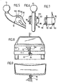
- a hitch shown in Fig. 1 comprises a ball neck 10 with a coupling ball 12, wherein the ball neck in a working position A in a Longitudinal plane 14 of a motor vehicle 16 extends and the Coupling ball 12 facing away on a roadway 18 Side of the ball neck 10 is.
- This ball neck 10 is in the first embodiment the hitch invention of a working position A in a rest position R pivotable, the Swivel axis can be aligned arbitrarily.
- the pivot axis can perpendicular to the longitudinal center plane 14 in horizontal direction, the pivot axis can in the Longitudinal plane 14 extend in approximately vertical direction.
- the pivot axis designated 22 in a Angle ⁇ with respect to the longitudinal center plane 14 of the motor vehicle 16 to let go the angle ⁇ in the range of is about 40 ° to about 70 ° and the pivot axis 22nd at an angle ⁇ relative to in the longitudinal center plane 14th lying horizontal 26 to let go, the Angle ⁇ is in the range of about 30 ° to about 50 °, and also the pivot axis 22 at an angle ⁇ a perpendicular to the longitudinal center plane 14 horizontal 24 to let go, the angle ⁇ im Range of about 20 ° to about 40 °.
- the first embodiment of a trailer coupling according to the invention now comprises for rotatable mounting of the ball neck 10 about the pivot axis 22nd a pivot bearing body 30, which for example a Base 32 and two projecting from the base 32 bearing cheeks 34th and 36.
- bearing cheeks 34 and 36 is a bearing pin 38 to his Axis 40 rotatably mounted, wherein the axis 40, the pivot axis 22 represents the ball neck 10.
- the bearing of the bearing pin 38 takes place in the bearing cheek 34, for example by means of a sliding bearing 42, formed by a peripheral surface 44 of the journal 38 and a Bearing bore 46 in the bearing cheek 34th
- the bearing pin 38 carries in its the bearing cheek 36th passing through an external thread 48, which in a Internal thread 50 engages in the bearing cheek 36, so that a Turning the bearing pin 38 causes that due to the interlocking threads 48 and 50 of the trunnions 40 in FIG a direction 52 parallel to the axis 40 relative to the bearing cheeks 34 and 36 can be moved.
- a pivot member 60 On the bearing pin 38 sits between the bearing cheek 34 and the bearing cheek 36 is a pivot member 60 as a whole, which rotatably connected to a pivot pinion 62 is, in turn driven by a pinion 64 is to a pivoting movement of the pivot member 60 to the Swivel axis 62 initiate.
- the pinion 64 is through a pivot drive 66 driven, which preferably also an electric motor with a reduction gear includes.
- pivot member 60 carries on its bearing cheek 36 facing side with a first positive locking elements 70th provided carrier 72, which in the simplest case as a toothed ring formed and concentric with the axis 40 of the Bearing pin 38 is arranged.
- the carrier 72 is non-rotatable and non-displaceable in the direction 52 connected to the pivot member 60, to which In addition, the ball neck 10 is formed.
- the ball neck 10, the pivoting element 60 and the carrier 72 with the first positive locking elements 70th formed as an integral part.
- a second positive locking elements 80 exhibiting carrier 82 arranged, wherein the second positive locking elements 80 the first positive locking elements 70 are facing and the first Positive locking elements 70 and the second positive locking elements 80th are formed so that these form-fitting and play-free Connect with each other to the pivoting element 60 play free rotation relative to the bearing cheek 36 set.
- the carrier 82 is formed as a separate part, which rotatably and in direction 52 immovable is connected to the bearing cheek 36. But it is also conceivable the second carrier 82 with the second positive locking elements 80 in one piece to form the bearing cheek 36.
- bearing pin 38 is on a pivot pinion 62 side facing provided with a shoulder 84, which is capable of the pivot pinion 62 together with the Swivel element 60 to move in the direction of the bearing cheek 36.
- bearing pin 38 is still further with a Shoulder 86 provided which, for example, by an attached Ring 88 is formed and serves to the pivoting element 60 in the direction of the bearing cheek 34 to move.
- pivot member 60 and the pivot pinion 62 are rotatable together, but in direction 52 substantially stored immovably on the bearing pin 38.
- the drive 58 is now in motion set, which via the pinion 56, the drive pinion 54th drives and thus is able to the bearing pin 38 in Direction 52 to move, either so that the Positive locking elements 70 and 80 engage each other, or so that they are disengaged, always the Pinion 64 and the pivot pinion 62 remain engaged.
- the hitch invention is preferably the ball neck 10 in a region between the coupling ball 12 and the pivot bearing body 30 with a receptacle 90 for a Housing 92 of a designated as a whole with 94 outlet provided, wherein the housing 92 on one side with a Lid 96 is provided and on an opposite side with a cap 98.
- the detection side 102 of the coupling ball 12 faces is such that an outgoing from the detection side 102 Detection area 104 as shown in Figs. 8, 9 and 10, the coupling ball 12 detected to essential parts, namely preferably such that at least half of the surface the coupling ball 12 can be seen whether on this, as in Fig. 10, a ball coupling 106 of a Trailer attacks and the coupling ball 12 in known Way comprises or whether the coupling ball 12 otherwise applied is, for example, by a shoe 108 or a another object. (Fig. 11)
- the senor 100 comprises a transmitter 110, which in the example, cone-shaped Detection area 104 airborne ultrasonic wave pulse packets 112 while one is also in the Sensor 100 provided detector 114 reflected, returning Ultrasonic wave pulse packets 116 detected.
- a transmitter 110 which in the example, cone-shaped Detection area 104 airborne ultrasonic wave pulse packets 112 while one is also in the Sensor 100 provided detector 114 reflected, returning Ultrasonic wave pulse packets 116 detected.
- the sensor 100 further comprises an evaluation 118, which are generated by evaluation of the detector 114 Signal in relation to the activity of the transmitter 110 capable is to determine whether the coupling ball 12, as in Fig. 8, 9, is free of external influence or whether this the ball coupling 106 or the object 108th Attack, as attacked by a on the coupling ball 12 attacking Object the transit time of the reflected ultrasonic wave pulse packets 116, which impinge on the detector 114, changes.
- the transmitter 118 Due to the changed duration of the reflected Ultrasonic wave pulse packets 116 is the transmitter 118 capable of outputting a detector signal SE, which is the existing or nonexistent effect on the Clutch ball 12 reports.
- a Ultrasonic transducer used to send the Ultraschallwellenimpulscous 112 as a transmitter and to detect the back-reflected ultrasonic wave pulse packets 116 as Detector is operable.
- an ultrasonic wave 112 emitting Transmitter 110 and an ultrasonic waves 116 detecting Detector 114 it is also conceivable infrared radiation with a corresponding transmitter 110 to send out and the infrared radiation with a correspondingly different detector 114 to detect or radar waves and send them to detect.
- the evaluation electronics 118 is, as shown in FIG. 13, connected to a sensor control circuit 120, which the Sensor 100 operates and, for example, a sensor 100 activating signal AK of the transmitter 118 then transmitted when the sensor 100 is to check whether the Clutch ball 12 is acted upon by an object or not.
- the sensor control circuit 120 is capable during defined detection time intervals Z with the signal AK the Sender 100 to activate, so that, for example, during the defined detection time intervals Z of the transmitter 110 the Ultrasonic waves 112 emits.
- the sensor control circuit 120 determines the transmitter 118, based on the signal received from the detector 114, whether the Coupling ball 12 is acted upon by an object or Not. If this is the case, as shown by way of example in FIG. 14, the sensor control circuit 120 always the transmitted from 0 different detector signal SE, if they in turn, with the signal AK activates the sensor 100.
- the sensor control circuit 120 in turn comprises a clock stage 122, which sets time intervals ⁇ t, the between the individual, consecutive, during the Detektionszeitintervals Z existing signal AK are.
- the time intervals ⁇ t are of different lengths adjustable.
- the sensor control circuit 120 If the sensor control circuit 120 has been activated, for example, by means of a start signal S, it enters its active state or mode and in this case the clock generator stage 122 generates the signals AK with time intervals ⁇ t 1 between them, which are the shortest possible.
- the clock stage 122 changes the time intervals ⁇ t to larger values, so that the latter now outputs the signals AK with time intervals ⁇ t 2 between them, these time intervals ⁇ t 2 being greater than the time intervals ⁇ t 1 .
- the clock generator stage 122 again changes the time intervals ⁇ t to even greater values, namely the values ⁇ t 3, and thus transmits the signals AK to the sensor 100 at even greater intervals during a period T 3 .
- the coupling ball 12 is checked very frequently by the sensor 100, while the frequency of the checks of the coupling ball 12 during the period T 2 becomes lower and becomes even lower during the period T 3 .
- the clock stage 122 After elapse of the period T 3 , the clock stage 122 no longer outputs signals AK, and thus the clock stage 122 of the sensor control circuit 120 transitions to its inactive state or inactive mode.
- the sensor control circuit includes 120 also has a memory stage 124, which, the from the evaluation 118 output detector signal SE stores until a re-activation of the sensor 100 is done by means of the signal AK and the transmitter 118 indicates by the signal SE, whether the coupling ball 12 through an object, such as the ball coupling 106, is charged or not.
- This storage stage 124 stores each of the sensor 100 detected impact state until the renewed query by the sensor 100, so that, as shown in Fig. 14, the Memory stage 124 is capable of a trailer presence signal To produce SZ, by means of which at any time t detected can be, whether the coupling ball 12 by a Object is acted upon or not.
- This trailer presence signal SZ is for example from a Control 130 of the hitch interrogated, the thus in is able to decide if at all the ball neck 10 may be swung out of the working position A or Not.
- the controller 130 includes, for example, a start button T, with which a movement of the ball neck 10th between the working position A and the rest position R triggered is. That is, when the button T in the rest position R the ball neck 10 is pressed, there is a pivoting of the ball neck 10 from the rest position R in the working position A, however, the button T is in the working position A is pressed, so pivoting of the ball neck 10 takes place from the working position A to the rest position R.
- a start button T with which a movement of the ball neck 10th between the working position A and the rest position R triggered is. That is, when the button T in the rest position R the ball neck 10 is pressed, there is a pivoting of the ball neck 10 from the rest position R in the working position A, however, the button T is in the working position A is pressed, so pivoting of the ball neck 10 takes place from the working position A to the rest position R.
- the controller 130 transmits the start signal S of the clock stage 122, which then during the period T 1 with short intervals .DELTA.t 1 the signal AK for activating the sensor 100 and at the same time stores the signal SE of the sensor 100, so that the controller 130 has the trailer presence signal SZ indicative of the state of action of the coupling ball 12 (FIG. 19).
- the controller 130 will first drive 58 to Release the fixation of the ball neck 10 in the working position A drive, then again query the status signal SZ and only when it is certain that the coupling ball 12 is not is acted upon by an object, the pivot drive 66th to control the ball neck 10 from the working position A in Towards the rest position R to pivot.
- a Sensor 140 is provided which checks whether a plug 142 a trailer is plugged into the socket 94 (FIG. 13 and 15).
- the senor 140 is a pushbutton 144 or Button formed, and it takes place when plugging the Plug 142 into the socket 94 an actuation of a Tastnase 146 of the key switch 144, which a switching contact 148 closes, which thus in the socket 94th Plug 142 of the controller 130, a trailer presence signal DZ reports.
- the controller 130 in terms of activation the drive 58 or the rotary actuator 66 is blocked
- the controller 130 is in terms of Activation of the drive 58 or the pivot drive 66 blocked.
- the push-button 144 sits in a for this purpose Contact socket 150 of socket 94 and is replaced by a projection 152 of the plug 142 is applied, wherein the projection 152, as shown in Fig. 15, the outer sleeve of Plug 142 may be, but it is also conceivable as a projection to provide an additional pin of the plug 142, which acts on the Tastnase 146.
- the senor 140 not as Actuate pushbutton 144, but as a proximity switch, which plugged into the socket 94 plug 142 detects without contact.
- the senor 140 As shown in Fig. 16, the sensor 140 as a detection circuit 154 designed for trailer-side electrical loads, which thus recognizes whether due to the in the socket 94 inserted plug 142 to the individual electrical Contacts the usual electrical loads, z. B. through the taillights and turn signals, are present.
- the detection circuit 154 generates the trailer presence signal DZ then, if these loads are present, because with it is ensures that not just any plug 142 in the Outlet 94 is plugged in, but the plug 142 actually with the usual electric in a trailer Loads connected.
- the detection circuit 154 is particularly easy realize that these each of the lines 156, the lead to the socket 94, taps and their resistance against Measures the mass then for the typical electrical load in the Trailer must correspond to corresponding resistance.
- the detection circuit 154 is switched to that they already have an existing electrical load between one of the lines 156 and ground the trailer presence signal DZ delivers, so this trailer presence signal also for example with a damaged trailer lamp is delivered.
- the sensor 140 designed as a detection circuit 154 can at any point of supply 158 of the trailer socket 94 be arranged and must therefore not necessarily in the Trailer socket 94 itself be arranged, the arrangement the detection circuit 154 between the individual Lines 156 connected switches for energizing the various lines 156 and the socket 94 arranged have to be.
- the controller 130 switches the sensor control circuit 120 and thus the sensor 100 by means of a switching signal SS at least when the ball neck 10 in the Resting position R or at least near the rest position R, to prevent when entering the rest position R the sensor 100 erroneously an admission of the Coupling ball 12 reports, although this is not the case but only the detection area 104, for example Body parts or other objects on the way to the Rest position detected.
- the sensor control circuit 120 and thus also the sensor 100 are turned on at least then by the switching signal SS, when the ball neck 10 in the working position A stands. But it is also possible, the sensor control circuit 120 already in all positions of the ball neck, which are close to working position A or the between a bottom dead center U of the coupling ball 12, in which this the road 18 comes closest, and the working position A are, so that for example already be recognized when swinging into the working position A. if that is provided for coupling the trailer Ball coupling 106 in the range of movement of Coupling ball 12 comes and the coupling ball 12, for example with this ball coupling piece 106 before reaching the Working position A or in working position A. would.
- the ball neck 10 from the rest position R pivoted into the working position A it takes place at the latest on reaching the working position A by the Start signal S is a start of the sensor control circuit 120 and, since it can be assumed that within a noteworthy attaching a trailer by putting on the trailer Ball coupling piece 106 takes place on the coupling ball 12, a frequent activation of the sensor 100 by means of the Signal AK.
- the ball coupling piece 106 placed If it is found that the ball coupling piece 106 placed is, then stores the memory stage 124 that the patch Ball coupling piece 106 corresponding detection signal SE, so that the controller 130 is always the status signal SZ is reported equal to 1, which documents that a Subject on the coupling ball 12 acts.
- the start signal S is not Mandatory to the signal of the button T or reaching the Working position coupled, but the signal S can, for example also by restarting the motor vehicle or certain driving conditions, that is, for example, a Reversing the motor vehicle, the sensor control circuit 120 are sent to verify a possible To act on the coupling ball 12 to cause.
- the Sensor 100 instead of working with ultrasound, also with Working infrared radiation and thus emit infrared radiation and the back-reflected infrared radiation, in particular which reflected back from the area of the coupling ball 12 Detect infrared radiation.
- the transmitter 110 is thus an infrared transmitter and the detector 114 is an infrared detector.
- the sensor 100 as a radar sensor form the electromagnetic waves in the frequency domain radar sends and receives.
- Such a sensor housing 164 is preferably so place the detection area 104 on the motor vehicle 16 facing surface region of the coupling ball 12th essentially completely check.
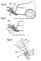
- a third embodiment of an inventive Towing device shown in FIGS. 18 and 19, is the Transmitter 110 'of the sensor 100' in an opening of the ball neck 10 used and produced by coupling to the ball neck 10 in the ball neck 10 structure-borne noise with ultrasonic waves 112 ', which propagate in the direction of the coupling ball 12, wherein the coupled system of transmitter 110 ', ball neck 10 and Clutch ball 12 operated in the region of its resonance frequency becomes, thereby amplitude and frequency of the ultrasonic waves of the structure-borne noise, their intensity and / or frequency changes when on the hitch ball the ball coupling 106 is seated or a rest of the object acts.
- the sensor 100 is in a bore 170 in FIG Ball neck 10 is arranged, which from a bottom 172 of the Ball neck 10 coaxially inserted into the coupling ball 12 in this is and for example in front of the coupling ball 12 adjacent constriction 174 ends, so that in the area of Constriction 174 and the coupling ball 12 no weakening of the material.
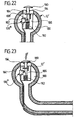
- the coupling ball 12 ' is hollow, wherein in an inner cavity 180 of the coupling ball 12 a Sensor 100 "'is provided with a push-button 182 detected a position of a Tastst Formulaels 184, which, for example is guided in a guide 186 in the cavity 180 and a curved path 188, which depends on the Position of the Tastst Schemeels 184 in different ways the key switch 182 acts, that is, for example, the Pushbutton 182 then acted when the Tastst Congressel 184, as shown in Fig. 23, acted upon by a force F. is, for example, by a on the coupling ball 12 ' mounted ball coupling 106 is generated.
- the tactile plunger 184 has a domed head 190, which approximately to an outer contour of the coupling ball 12 is adapted and by means of a spring 192 from an upper side 194 of the guide 186 is kept lifted, as long as the force F is not effective.
- Effective force F is the Head 190 in the direction of the top 194 of the guide 186 pressed and thus the cam track 188 causes an actuation of the touch sensor 100 "', which then its switching state relative to the non-actuated position of the Tastst formulateels 184th has changed.
- Towing device can account for the sensor control circuit 120, because the push button 100 "always clear and without power can report a switching state, which of the admission or non-loading of the coupling ball 12 ', so that the tact sensor 100 "'directly the Trailer presence signal SZ of the controller 130 available can make.
- the provided with the cavity 180 coupling ball 12 ' is suitable but also for the installation of a coupled to this ultrasonic transducer 110 ', which in the region of the resonant frequency is operated.
- the senor 100 "" includes a key switch 202 a nose 204, which by a cam 206 of a detector lever 208 is operable, which in turn about an axis 210 is pivotally mounted on the ball neck 10.
- the detector lever 208 is formed so that it is in a first position with an end 212 near the coupling ball 12 is, for example, at a small distance from this or is applied to this, so that in this first position of the Detector lever 208 to the coupling ball 12 is not a ball coupling 106 can attack or be put on can.
- end 212 is so far away from the coupling ball 12 movable that the ball coupling 106 can be placed.
- the cam 206 is now formed so that it the push button 202 in standing in the first position detector lever 208 is not actuated while the cam 206 the push button 202 then actuated when the detector lever 208 in its second position, in which the end 212 of the coupling ball 12 is moved away.
- the key switch 202 in the same way as the key switch 182 immediately the trailer presence signal SZ and provides this is available to the controller 130.
- the key switch 202 is near the socket 94 arranged so that in a simple manner via the supply line to Socket 94 also the electrical query of the push-button 202 can take place.
- the key switch 202 in the housing for the outlet immediately and over a between this and the cam 206 effective ram the push button 202 to operate.
Abstract
Description
Die Erfindung betrifft eine Anhängevorrichtung für Kraftfahrzeuge, umfassend einen an einer fahrzeugfesten Aufnahme gehaltenen Kugelhals, der an seinem der Aufnahme abgewandten Ende eine Kupplungskugel trägt, eine Fixiereinrichtung, welche in einem Fixierzustand den Kugelhals in einer Arbeitsstellung festlegt und welche in einem Lösezustand den Kugelhals für eine Bewegung aus der Arbeitsstellung freigibt.The invention relates to a towing device for motor vehicles, comprising a held on a vehicle-mounted recording Ball neck, which faces away from the receptacle End carries a coupling ball, a fixing device, which in a state of fixation the ball neck in a working position determines and which in a release state the ball neck releases for movement out of the working position.
Derartige Anhängevorrichtungen sind aus dem Stand der Technik bekannt. Bei diesen besteht das Problem, daß nicht sichergestellt ist, daß der Übergang der Fixiereinrichtung vom Fixierzustand in den Lösezustand oder umgekehrt unter Bedingungen erfolgt, die sicherheitstechnisch zulässig sind.Such hangers are known in the art known. In these, the problem is that not ensured is that the transition of the fixing of the Fixing state in the release state or vice versa Conditions that are permissible in terms of safety.
Der Erfindung liegt daher die Aufgabe zugrunde, eine Anhängevorrichtung der gattungsgemäßen Art derart zu verbessern, daß diese funktionssicher arbeitet.The invention is therefore based on the object, a hitch to improve the generic type such that this works reliably.
Diese Aufgabe wird bei einer Anhängevorrichtung der eingangs beschriebenen Art erfindungsgemäß dadurch gelöst, daß die Anhängevorrichtung mit mindestens einem ein Indiz für die Präsenz eines Anhängers erfassenden Sensor zum Erzeugen eines Anhängerpräsenzsignals versehen ist, daß eine Steuerung vorgesehen ist, mit welcher eine Änderung des Zustands der Fixiereinrichtung blockierbar ist, und daß die Steuerung das Anhängerpräsenzsignal des mindestens einen Sensors abfragt und beim Vorliegen des Anhängerpräsenzsignals eine Änderung des Zustands der Fixiereinrichtung blockiert.This object is in a hitch of the above described type inventively achieved in that the hitch with at least one an indication of the Presence of a trailer detecting sensor for generating a Trailer presence signal is provided that a controller provided is with which a change of state of Fixing device is blocked, and that the controller Queries trailer presence signal of at least one sensor and a change in the presence of the trailer presence signal the state of the fixing blocked.
Der Vorteil der erfindungsgemäßen Lösung ist somit darin zu sehen, daß bereits bei Vorliegen des Anhängerpräsenzsignals eine Zustandsänderung der Fixiereinrichtung automatisch verhindert wird und somit Fehlfunktionen vermieden werden.The advantage of the solution according to the invention is thus too see that already in the presence of the trailer presence signal a state change of the fixing automatically prevented and thus malfunctions are avoided.
Insbesondere wird bei der erfindungsgemäßen Lösung ein Übergang der Fixiereinrichtung von dem Fixierzustand in den Lösezustand verhindert, so daß damit eine der schwerwiegendsten Fehlfunktionen einer derartigen Anhängevorrichtung ausgeschlossen ist.In particular, in the solution according to the invention a transition the fixing device of the fixing state in the release state prevented, making it one of the most serious Malfunction of such a hitch excluded is.
Prinzipiell ist es im Rahmen der erfindungsgemäßen Lösung denkbar, daß die Steuerung einen Sensor abfragt, welcher ein Indiz für die Präsenz eines Anhängers erfaßt.In principle, it is within the scope of the inventive solution conceivable that the controller queries a sensor, which a Indicator recorded for the presence of a trailer.
Besonders günstig ist es jedoch, wenn die Steuerung die Anhängerpräsenzsignale mehrerer Sensoren abfragt und bei Vorliegen bereits eines Anhängerpräsenzsignals eine Änderung des Zustands der Fixiereinrichtung blockiert, so daß hierdurch die Sicherheit noch deutlich erhöht werden kann.It is particularly favorable, however, if the controller the Queries trailer presence signals of multiple sensors and if present already a trailer presence signal a change of State of the fixing blocked so that thereby the security can be increased significantly.
Insbesondere besteht die Möglichkeit, in unterschiedlicher Weise Indizien für die Anhängerpräsenz abzufragen und somit die Sicherheitsfunktionen zu verbessern, so daß bei eventueller Fehlanzeige eines der Sensoren damit gerechnet werden kann, daß der andere der Sensoren auf alle Fälle zu einer Blockierung der Fixiereinrichtung führt.In particular, there is the possibility in different Way to query indicia of trailer presence and thus to improve the security functions, so that in eventual Nil one of the sensors can be expected can be that the other of the sensors in any case to a Blocking the fixer leads.
Hinsichtlich der Art und Weise, welche Indizien von den Sensoren erfaßt werden, wurden bislang keine näheren Angaben gemacht. So sind die unterschiedlichsten Indizien für einen Anhänger durch einen Sensor detektierbar.Regarding the way, which indications of the Sensors are detected, have been no further details made. So are the most varied evidence for one Trailer detectable by a sensor.
Ein derartiges Indiz könnte beispielsweise eine Erfassung der Zug- oder Stützlast auf die Kupplung sein.Such an indication could be, for example, a detection of Tensile or support load on the coupling.
Eine besonders vorteilhafte Lösung sieht vor, daß der Sensor eine Anhängerstromversorgung überwacht und deren Existenz als Indiz für einen angehängten Anhänger wertet und in diesem Fall das Anhängerpräsenzsignal abgibt.A particularly advantageous solution provides that the sensor monitored a trailer power supply and their existence as Indicator for an attached trailer evaluates and in this Case the trailer presence signal outputs.
Eine derartige Überwachung der Anhängerstromversorgung kann ebenfalls in unterschiedlichster Art und Weise erfolgen.Such monitoring of the trailer power supply can also done in different ways.
Eine vorteilhafte Lösung sieht vor, daß der Sensor einen in die Steckdose für die Anhängerstromversorgung eingesteckten Stecker des Anhängers erkennt. Dabei wird die Existenz des in die Steckdose eingesteckten Steckers als ein Indiz für einen Anhänger angesehen.An advantageous solution provides that the sensor has a in plugged in the socket for the trailer power supply Plug of the trailer recognizes. The existence of the in the socket plugged in as an indication of a Trailer viewed.
Diese Überprüfung der Existenz des Steckers könnte über die eingesteckten elektrischen Kontakte erfolgen.This review of the existence of the plug could be about plugged electrical contacts.
Eine besonders einfache Lösung sieht vor, daß der Sensor einen Steckerkörper des in die Steckdose eingesteckten Steckers erfaßt und somit über die Erfassung der Präsenz des Steckerkörpers den in die Steckdose eingesteckten Stecker erkennt.A particularly simple solution provides that the sensor a plug body of the plugged into the socket Plug detected and thus on the detection of the presence of Plug body plugged into the socket recognizes.
Dies könnte beispielsweise mit einem berührungslosen Schalter erfolgen. Eine besonders einfache Lösung sieht jedoch vor, daß der den Steckerkörper erfassende Sensor einen Tastschalter umfaßt.This could be done, for example, with a non-contact switch respectively. A particularly simple solution, however, provides in that the sensor which detects the plug body is a push-button switch includes.
Alternativ oder ergänzend zum Erfassen des in die Steckdose eingesteckten Steckers als Indiz für den Anhänger sieht eine weitere Lösung vor, daß der Sensor als eine elektrische Last des Anhängers erkennende Schaltung ausgebildet ist.Alternatively or in addition to detecting the in the socket inserted plug as an indication of the trailer looks one Another solution that the sensor as an electrical load the trailer recognizing circuit is formed.
Damit erfaßt der Sensor nicht die Präsenz des Steckers, sondern erfaßt, ob mit der Steckdose eine elektrische Last verbunden ist, die typisch für einen Anhänger ist.Thus, the sensor does not detect the presence of the plug, but detects whether with the socket an electrical load connected, which is typical for a trailer.
Ein derartiger Sensor kann nun zwar in der Steckdose angeordnet sein. Eine besonders günstige Lösung sieht jedoch vor, daß der Sensor in eine Versorgung für die Steckdose integriert ist und somit unabhängig von der Steckdose angeordnet sein kann.Such a sensor can now be arranged in the socket be. However, a particularly favorable solution provides that the sensor is integrated into a power supply for the socket is and thus arranged independently of the socket can be.
Alternativ oder ergänzend zur Überwachung der Anhängerstromversorgung sieht eine weitere vorteilhafte Lösung vor, daß der Sensor die Kupplungskugel überwacht und ein Angreifen des Objekts an der Kupplungskugel als Indiz für die Präsenz eines Anhängers wertet.Alternatively or in addition to monitoring the trailer power supply provides a further advantageous solution that the sensor monitors the coupling ball and attacking the Object on the coupling ball as an indication of the presence of a Trailer evaluates.
Der Vorteil dieser Lösung ist darin zu sehen, daß der tatsächlich für die Sicherheit bei der Zustandsänderung der Fixiereinrichtung relevante Tatbestand erfaßt wird, nämlich die Präsenz eines an der Kupplungskugel angreifenden Objekts, wobei eine derartige Erfassung eines an der Kupplungskugel angreifenden Objekts auch möglicherweise Situationen mit als Indiz für die Präsenz eines Anhängers wertet, die tatsächlich gar nicht die Präsenz eines Anhängers darstellen.The advantage of this solution is the fact that the actual for the security of the state change of Fixing device relevant fact is detected, namely the presence of an object acting on the coupling ball, such a detection on the coupling ball The attacking object may also have situations with it Indicator for the presence of a trailer that actually evaluates not at all the presence of a trailer.
Dennoch ist es aus Sicherheitsgründen vorteilhafter, Tatbestände mitzuerfassen, die tatsächlich nicht die Präsenz eines Anhängers darstellen, wenn damit jedoch sichergestellt werden kann, daß in all den Fällen, in welchen ein Anhänger an der Kupplungskugel angreift, eine Blockierung der Fixiereinrichtung erfolgt.Nevertheless, it is advantageous for security reasons, facts that actually does not capture the presence of a trailer, but if so ensured can be that in all cases in which a follower engages the coupling ball, blocking the fixing he follows.
Hinsichtlich der Anordnung eines derartigen Sensors wurden im Zusammenhang mit der bisherigen Erläuterung der erfindungsgemäßen Lösung keine näheren Angaben gemacht. So ist es beispielsweise denkbar, daß der Sensor im Bereich einer Steckdose angeordnet ist. Diese Lösung hat den Vorteil, daß bei der Steckdose ohnehin eine elektrische Verbindung zur Bordelektrik des Kraftfahrzeugs vorliegt und somit in einfacher Weise eine Versorgung und eine Kommunikation mit dem Sensor erfolgen kann.With regard to the arrangement of such a sensor were in Context with the previous explanation of the invention Solution no details provided. That's the way it is, for example conceivable that the sensor in the range of a socket is arranged. This solution has the advantage that at the socket anyway an electrical connection to the on-board electrical system of the motor vehicle is present and thus in a simple Make a supply and a communication with the sensor can be done.
Hinsichtlich der Realisierbarkeit ist es besonders günstig, wenn der Sensor in die Steckdose integriert ist und somit auch mechanisch ein einfacher Schutz für den Sensor erhältlich ist, da die Steckdose ohnehin möglichst geschützt angeordnet werden soll. With regard to the feasibility, it is particularly favorable if the sensor is integrated into the socket and thus also mechanically a simple protection for the sensor available is because the outlet anyway arranged as protected as possible shall be.
Im Fall des Vorsehens des Sensors an der Steckdose kann die Steckdose, wie konventionell bekannt, dem Kugelhals zugeordnet sein, jedoch neben der Anhängevorrichtung angeordnet sein.In the case of providing the sensor to the socket, the Socket, as conventionally known, associated with the ball neck be, but arranged next to the hitch be.
Eine weitere vorteilhafte Möglichkeit der Anordnung des Sensors sieht vor, daß der Sensor am Kugelhals angeordnet ist. Diese Lösung hat den großen Vorteil, daß mit dieser der Sensor mit einfachen Mitteln möglichst nahe der Kupplungskugel angeordnet werden kann und somit eine möglichst direkte Überwachung der Kupplungskugel, insbesondere mit erheblicher Reduktion von Störungen, erfolgen kann.Another advantageous way of arranging the Sensor provides that the sensor is arranged on the ball neck is. This solution has the great advantage that with this the Sensor with simple means as close as possible to the coupling ball can be arranged and thus a direct as possible Monitoring the coupling ball, especially with considerable Reduction of interference, can be done.
Dabei kann der Sensor beispielsweise auf einer Oberfläche des Kugelhalses, beispielsweise in einem Gehäuse, fixiert sein.In this case, the sensor can, for example, on a surface of the Ball neck, for example, be fixed in a housing.
Da an dem Kugelhals in vielen Fällen eine Steckdose angeordnet ist, ist es besonders zweckmäßig, den Sensor in der Steckdose anzuordnen, um in einfacher Weise die ohnehin vorhandene Verbindung zur Bordelektrik oder Bordelektronik nutzen zu können.As arranged on the ball neck in many cases, a power outlet is, it is particularly appropriate to the sensor in the To arrange the socket to easily the already existing Connection to on-board electrical system or on-board electronics to be able to use.
In diesem Fall ist diese Lösung besonders günstig, da mit der am Kugelhals vorgesehenen Steckdose die Möglichkeit besteht, den Sensor möglichst nahe an der Kupplungskugel zu plazieren.In this case, this solution is particularly favorable because with the at the ball neck provided socket is possible To place the sensor as close to the coupling ball.
Dabei könnte der Sensor beispielsweise zusätzlich zum Steckdosengehäuse mit diesem verbunden angeordnet sein.The sensor could, for example, in addition to the socket housing be arranged connected to this.
Eine hinsichtlich der Funktionssicherheit und der Herstellbarkeit besonders günstige Lösung sieht jedoch vor, daß der Sensor in die Steckdose integriert ist, das heißt, daß beispielsweise der Sensor und die Steckdose in einem gemeinsamen Gehäuse angeordnet sind.One in terms of reliability and manufacturability However, particularly favorable solution provides that the Sensor is integrated into the socket, that is, for example the sensor and the socket in one common Housing are arranged.
Eine besonders zweckmäßige Lösung sieht dabei vor, den Sensor bei einer im Kugelhals integrierten Steckdose im Bereich eines über den Kugelhals überstehenden Gehäuseteils vorzusehen.A particularly expedient solution provides, the sensor at a socket integrated in the ball neck in the area to provide a protruding over the ball neck housing part.
Eine andere vorteilhafte Möglichkeit der Unterbringung des Sensors sieht vor, daß der Sensor im Kugelhals angeordnet ist, wodurch ein optimaler Schutz für den Sensor gegeben ist.Another advantageous way of housing the Sensor provides that the sensor is located in the ball neck is, whereby an optimal protection for the sensor is given.
Hinsichtlich der Detektion eines an der Kupplungskugel angreifenden Objekts sind die unterschiedlichsten Lösungsmöglichkeiten denkbar. So sieht eine vorteilhafte Ausführungsform vor, daß der Sensor über einen seitlich des Kugelhalses in Richtung der Kupplungskugel verlaufenden Erfassungsbereich die Kupplungskugel erfaßt, wobei vorzugsweise ein vom Erfassungsbereich überdeckter Bereich der Oberfläche der Kupplungskugel erfaßt wird.With regard to the detection of one on the coupling ball attacking object are a variety of possible solutions conceivable. This is an advantageous embodiment before that the sensor over a side of the ball neck in the direction of the coupling ball extending detection area detects the coupling ball, preferably an area of the surface covered by the detection area the coupling ball is detected.
Alternativ oder ergänzend dazu sieht ein weiteres Ausführungsbeispiel vor, daß der Sensor das an der Kupplungskugel angreifende Objekt über den sich zwischen dem Sensor und der Kupplungskugel erstreckenden Abschnitt des Kugelhalses detektiert.Alternatively or additionally, another embodiment provides before, that the sensor on the coupling ball attacking object over which is between the sensor and the Coupling ball extending portion of the ball neck detected.
Ein derartiges Detektieren kann über eine Vielzahl von Mechanismen erfolgen, die sich auf den Abschnitt des Kugelhalses zwischen dem Sensor und der Kupplungskugel auswirken. Beispielsweise kann dies jegliche Art von Materialbelastung oder Änderung von Materialeigenschaften sein, die über einen hierzu geeigneten Sensor detektiert werden.Such detection may be via a variety of mechanisms take place, referring to the section of the ball neck between the sensor and the coupling ball. For example This can be any kind of material load or Change of material properties that have a For this purpose, suitable sensor can be detected.
Besonders vorteilhaft ist es, die Einwirkung auf die Kupplungskugel über Körperschall zu erfassen, der sich über den zwischen Sensor und Kupplungskugel erstreckenden Abschnitt des Kugelhalses ausbreitet.It is particularly advantageous, the action on the Clutch ball to detect structure-borne noise, which is about extending between the sensor and coupling ball section of the ball neck spreads.
Eine weitere Möglichkeit zum Erfassen der Einwirkung eines Objekts auf die Kupplungskugel ist die, den Sensor in der Kupplungskugel selbst anzuordnen, wobei alle Detektionsmöglichkeiten, wie z. B. Ultraschall, Infrarot oder mechanische Betätigung, möglich sind.Another way to detect the action of a Object on the coupling ball is the, the sensor in the Self-locating coupling ball, with all detection options, such as As ultrasound, infrared or mechanical Actuation are possible.
In diesem Fall läßt sich die Einwirkung eines Objekts auf die Kupplungskugel besonders günstig erfassen, allerdings ist in diesem Fall die Kupplungskugel mit den notwendigen Hohlräumen zu versehen.In this case, the influence of an object on the Coupling ball particularly low capture, however, is in In this case, the coupling ball with the necessary cavities to provide.
Besonders günstig läßt sich dies realisieren, wenn der Sensor einen einer Seite der Kupplungskugel zugeordneten Erfassungsbereich aufweist, das heißt, wenn der in der Kupplungskugel angeordnete Sensor beispielsweise einen oberen der Fahrbahn abgewandten Bereich der Kupplungskugel oder auch einen seitlichen Bereich der Kupplungskugel zu detektieren in der Lage ist. This can be realized particularly favorably if the sensor one of a side of the coupling ball associated detection range that is, when in the hitch ball arranged sensor, for example, an upper of the road remote region of the coupling ball or a lateral Detect area of the coupling ball in position is.
Es ist aber auch denkbar, den Sensor so auszubilden, daß dieser alle wesentlichen Oberflächenbereiche der Kupplungskugel erfaßt, an denen ein Objekt angreifen kann.But it is also conceivable to form the sensor so that this all essential surface areas of the coupling ball detected at which an object can attack.
Die Anordnung des Sensors in der Kupplungskugel ist insbesondere dann vorteilhaft, wenn der Sensor ein Tastsensor ist, das heißt, wenn mittels des Sensors ein Abtasten mindestens einer Seite der Kupplungskugel erfolgen soll.The arrangement of the sensor in the coupling ball is particular advantageous if the sensor is a touch sensor, that is, if by means of the sensor scanning at least one side of the coupling ball should be made.
Hinsichtlich der Art des Sensors wurden bislang keine näheren Angaben gemacht. So sieht eine einfache Art der Ausbildung des Sensors vor, daß der Sensor als durch Einwirkung betätigbarer Sensor arbeitet.With regard to the type of sensor were so far no closer Information provided. This is a simple way of training of the sensor, that the sensor as actuated by action Sensor works.
Ein derartiger durch Einwirkung betätigbarer Sensor ist beispielsweise ein Sensor, bei welchem eine mechanische Einwirkung erkannt wird und diese dann zum Auslösen des Anhängerpräsenzsignals führt. Eine andere Realisierungsform eines derartigen durch Einwirkung betätigbaren Sensors ist eine solche, bei welchem eine manuelle Einwirkung erkannt wird und zur Auslösung des Anhängerpräsenzsignals führt.Such an action-actuatable sensor is, for example a sensor in which a mechanical action is detected and then to trigger the Trailer presence signal leads. Another form of realization such an action operable sensor one in which a manual action is detected and triggers the trailer presence signal.
Eine besonders günstige Realisierungsform eines derartigen durch Einwirkung betätigbaren Sensors ist die, daß der Sensor einen Taststößel aufweist, dessen Stellungen erfaßbar sind und bei welchem insbesondere das Erreichen einer Stellung zum Auslösen des Signals führt.A particularly advantageous implementation of such action-actuable sensor is that the sensor having a Taststößel whose positions can be detected and in which in particular the achievement of a position for Triggering the signal leads.
Eine andere vorteilhafte Realisierungsform eines derartigen durch Einwirkung betätigbaren Sensors ist die, daß der Sensor einen Detektorhebel aufweist, dessen Stellungen erfaßbar sind, wobei bei einer dieser Stellungen eine Auslösung des Anhängerpräsenzsignals erfolgt.Another advantageous implementation of such action-actuable sensor is that the sensor having a detector lever whose positions detectable are, wherein at one of these positions triggering the Trailer presence signal takes place.
Das Erfassen der Einwirkung kann in unterschiedlichster Art und Weise erfolgen. Eine besonders einfache Lösung sieht vor, daß der Sensor einen Schalter umfaßt.The detection of the influence can be of various kinds and done way. A particularly simple solution provides that the sensor comprises a switch.
Dieser Schalter kann auch ein berührungsloser Schalter sein.This switch can also be a non-contact switch.
Besonders günstig ist es, wenn der Sensor einen mechanisch betätigbaren Schalter umfaßt, welcher sich beispielsweise durch den Taststößel oder durch den Detektionshebel betätigen läßt.It is particularly favorable if the sensor has a mechanical operable switch includes, which, for example Press the push rod or the detection lever leaves.
Beispielsweise läßt sich ein derartiger Sensor besonders einfach als mechanischer Tastsensor realisieren, welcher im einfachsten Fall einen Schalter umfaßt.For example, such a sensor can be particularly simple realize as a mechanical push button, which in the simplest Case includes a switch.
Mit einem derartigen Schalter ist in besonders einfacher Weise ein Zustandssignal bezüglich des Angreifens oder Nichtangreifens des Objekts an der Kupplungskugel generierbar.With such a switch is particularly simple Make a state signal regarding attacking or non-attacking of the object can be generated on the coupling ball.
Darüber hinaus besteht aber auch die Möglichkeit, einen als Tastsensor arbeitenden Sensor am Kugelhals anzuordnen, wobei der Tastsensor in diesem Fall ebenfalls als mechanischer Tastsensor ausgebildet sein könnte.In addition, there is also the possibility of a Tastsensor working sensor to be arranged on the ball neck, wherein the push button sensor in this case also as a mechanical Touch sensor could be designed.
Alternativ zur Ausbildung des Sensors als Tastsensor sieht eine besonders günstige Lösung vor, daß der Sensor berührungslos arbeitet. As an alternative to the design of the sensor as a push button sensor sees a particularly favorable solution that the sensor without contact is working.
Ein berührungslos arbeitender Sensor ist in unterschiedlichster Art und Weise realisierbar. Eine Lösung sieht vor, daß der Sensor als optischer Sensor arbeitet, beispielsweise mit Infrarotstrahlung.A non-contact sensor is in very different Way realizable. A solution provides that the sensor operates as an optical sensor, for example with infrared radiation.
Eine andere vorteilhafte Lösung sieht vor, daß der Sensor als Radarsensor arbeitet.Another advantageous solution provides that the sensor as Radar sensor works.
Ferner ist es beispielsweise denkbar, daß der Sensor als Ultraschallsensor arbeitet.Furthermore, it is conceivable, for example, that the sensor as Ultrasonic sensor works.
Dabei sind zwei verschiedene Ultraschalldetektionsmethoden möglich, nämlich einmal Detektion über sich in Luft ausbreitenden Ultraschall oder Detektion über sich als Körperschall ausbreitenden Ultraschall.There are two different ultrasound detection methods possible, namely once detection of airborne spreading Ultrasound or detection above itself as structure-borne noise spreading ultrasound.
Eine besonders vorteilhafte Ausführungsform eines erfindungsgemäßen berührungslos arbeitenden Sensors sieht jedoch vor, daß dieser einen Sender und einen Detektor umfaßt und somit das vom Sender ausgesandte Signal je nach dem, ob ein Objekt am Kugelhals angreift oder nicht, Veränderungen erfährt, die durch den Detektor erfaßbar sind.A particularly advantageous embodiment of an inventive Non-contact sensor, however, provides that this comprises a transmitter and a detector and thus the signal emitted by the transmitter depending on whether an object at the ball neck attacks or not, undergoes changes that can be detected by the detector.
Diese Lösung wird insbesondere bei Detektion über Infrarot, Radarwellen oder Ultraschall in Luft eingesetzt.This solution is particularly useful in detection via infrared, Radar waves or ultrasound used in air.
In diesem Fall sind auch die Anordnung des Sensors am Kugelhals oder in der Kupplungskugel nicht nur als Alternativen anzusehen, sondern es können auch beide Fälle auftreten, bei denen ein Teil des Sensors am Kugelhals und der andere in der Kupplungskugel angeordnet ist. In this case, the arrangement of the sensor on the ball neck are also or in the hitch ball not just as alternatives but both cases can occur one part of the sensor on the ball neck and the other in the Coupling ball is arranged.
Alternativ zum Vorsehen eines Sensors, welcher einen Sender und einen Detektor umfaßt, besteht auch die Möglichkeit, den Sensor mit einem einzigen Wandler auszustatten.Alternatively, to provide a sensor which includes a transmitter and a detector, it is also possible, the Equip sensor with a single transducer.
Ein derartiger Wandler kann beispielsweise sowohl als Sender oder als Empfänger betreibbar sein.Such a converter can, for example, both as a transmitter or be operable as a receiver.
Es besteht aber auch die Möglichkeit, bei Verwenden eines einzigen Wandlers diesen bei der Resonanzfrequenz des Wandlers und der an diesen ankoppelnden Umgebung zu betreiben, wobei die Beeinflussung der Resonanzfrequenz durch körperliche Beeinflussung der ankoppelnden Umgebung des Wandlers erfolgt.But there is also the possibility of using a single converter this at the resonant frequency of the Converter and to operate in this docking environment, wherein the influence of the resonance frequency by physical influence on the coupling environment of the Converter takes place.
Beispielsweise besteht im Fall eines Ultraschallwandlers die Möglichkeit, die Resonanzfrequenz des Ultraschallwandlers durch die ankoppelnde Umgebung, also beispielsweise durch die nahe an demselben angeordnete und durch Körperschall angekoppelte Kupplungskugel, zu beeinflussen, wobei je nach dem, ob an der Kupplungskugel ein Objekt angreift oder nicht, der Wandler seine Resonanzfrequenz ändert.For example, in the case of an ultrasonic transducer, the Possibility, the resonant frequency of the ultrasonic transducer through the coupling environment, so for example by the arranged close to the same and coupled by structure-borne sound Coupling ball, depending on which, whether an object attacks on the coupling ball or not, the Converter changes its resonant frequency.
Prinzipiell kann der Sensor so ausgebildet sein, daß er alle Objekte erfaßt, die an der Kupplungskugel angreifen.In principle, the sensor can be designed so that it all Detected objects that attack the coupling ball.
Es ist aber auch im Rahmen der angegebenen Lösung der Fall denkbar, daß der Sensor als an der Kupplungskugel angreifendes Objekt nur ein Kugelkupplungsstück oder ein ähnlich nachhaltig an der Kupplungskugel angreifendes Objekt erfaßt, welches zur Verbindung eines Anhängers mit der erfindungsgemäßen Anhängevorrichtung dient und in bekannter Weise die Kupplungskugel umgreift.But it is also within the specified solution of Case conceivable that the sensor as acting on the coupling ball Object only a ball coupler or a similarly sustained attacking on the coupling ball object which is used for connecting a trailer with the invention Towing device is used and in a known manner the coupling ball engages around.
Um insbesondere bei fortlaufender Überwachung der Kupplungskugel die Sensoraktivitäten zeitlich zu beschränken, insbesondere in den Fällen, in denen der Sensor nennenswert Leistung zur Detektion eines an der Kupplungskugel angreifenden Objekts benötigt, oder in den Fällen, in denen der Sensor für die Umgebung oder Bedienungsperson erkennbar arbeitet, ist dem Sensor vorzugsweise eine Steuerschaltung zugeordnet, welche den Sensor während Detektionszeitintervallen aktiviert, den vom aktivierten Sensor erkannten Zustand speichert und anschließend den Sensor deaktiviert.In particular, with continuous monitoring of the coupling ball to limit the sensor activities in time, in particular in cases where the sensor is worth mentioning Power for detecting an attacking on the coupling ball Object needed, or in cases where the sensor recognizable for the environment or operator, the sensor is preferably associated with a control circuit, which activates the sensor during detection time intervals, stores the state detected by the activated sensor and then deactivate the sensor.
Eine derartige Lösung hat den großen Vorteil, daß der Sensor nicht ständig arbeitet, sondern daß der Sensor beispielsweise nur zu Zeiten aktiviert wird, in denen zu erwarten ist, daß sich eine Änderung des Einwirkungszustandes der Kupplungskugel ergibt oder wenn der Einwirkungszustand der Kupplungskugel beachtlich ist.Such a solution has the great advantage that the sensor not constantly working, but that the sensor, for example is activated only at times in which it is expected that a change in the state of action of the coupling ball gives or if the state of action of the coupling ball is considerable.
Beispielsweise sieht diese Sensorsteuerschaltung vor, daß eine Aktivierung des Sensors bei Anliegen eines Startsignals für die Sensorsteuerschaltung erfolgt, dann den Einwirkungszustand der Kupplungskugel erfaßt und speichert und schließlich eine Deaktivierung des Sensors erfolgt.For example, this sensor control circuit provides that an activation of the sensor when a start signal is applied for the sensor control circuit, then the action state the coupling ball detects and stores and finally a deactivation of the sensor takes place.
Hinsichtlich der Speicherzeitdauer sind die unterschiedlichsten Möglichkeiten denkbar. With regard to the storage period, the most varied Possibilities conceivable.
Beispielsweise ist es denkbar, den vom Sensor erkannten Einwirkungszustand für eine definierte Zeit nach Deaktivierung des Sensors noch zu speichern und somit erkennbar zu halten.For example, it is conceivable that detected by the sensor exposure state for a defined time after deactivation to save the sensor yet and thus to keep recognizable.
Eine besonders günstige Lösung sieht vor, daß die Sensorsteuerschaltung den vom aktivierten Sensor erkannten Einwirkungszustand so lange speichert, bis eine erneute Aktivierung des Sensors erfolgt.A particularly favorable solution provides that the sensor control circuit the state of action detected by the activated sensor stores as long until a re-activation the sensor takes place.
Um mit einem erfindungsgemäßen Sensor über einen gewissen Zeitraum den Einwirkungszustand der Kupplungskugel überprüfen zu können, ist vorzugsweise vorgesehen, daß die Sensorsteuerschaltung nach einem festlegbaren Zeitintervall den Sensor erneut aktiviert und den von diesem erfaßten Zustand speichert.To be with a sensor according to the invention over a certain Period check the state of action of the coupling ball to be able to, it is preferably provided that the sensor control circuit after a definable time interval the sensor re-activated and the state detected by this stores.
Dabei ist es denkbar, dieses Zeitintervall fest vorzugeben, so daß nach Deaktivierung des Sensors das Zeitintervall abgewartet wird und dann selbständig durch die Sensorsteuerschaltung eine erneute Aktivierung des Sensors erfolgt.It is conceivable to predetermine this time interval, so that after deactivation of the sensor, the time interval waited and then independently by the sensor control circuit a renewed activation of the sensor takes place.
Dies hätte jedoch zur Konsequenz, daß eine einmal gestartete Sensorsteuerschaltung stets nach Ablauf des Zeitintervalls erneut den Sensor aktiviert, so lange bis die Sensorsteuerschaltung abgeschaltet wird.However, this would have the consequence that a once started Sensor control circuit always after the expiration of the time interval again activates the sensor until the sensor control circuit is switched off.
Noch vorteilhafter ist es jedoch, wenn die Sensorsteuerschaltung das Zeitintervall nach festgelegten Zeiträumen verändert. However, it is even more advantageous if the sensor control circuit changed the time interval after specified periods.
So ist es beispielsweise denkbar, nach einem Startsignal für die Sensorsteuerschaltung zunächst während eines ersten Zeitraums stets nach kurzen Zeitintervallen den Sensor erneut zu aktivieren, dann jedoch nach Ablauf dieses ersten Zeitraums die Zeitintervalle zu vergrößern und beispielsweise während eines zweiten Zeitraums den Sensor stets nach Ablauf der verlängerten Zeitintervalle erneut zu aktivieren.So it is conceivable, for example, for a start signal for the sensor control circuit first during a first period always after short time intervals, the sensor again activate, but after this first period has expired to increase the time intervals and, for example, during a second period, the sensor always after the expiration of the extended To reactivate time intervals.
Um insbesondere während Standzeiten des Kraftfahrzeugs oder längerer Fahrten Leistung zu sparen, ist es ferner vorteilhaft, wenn die Sensorsteuerschaltung nach Ablauf eines aktiven Modes in einen inaktiven Mode übergeht, in welchem keine selbständige Aktivierung des Sensors mehr erfolgt.In particular, during life of the motor vehicle or longer trips to save power, it is also advantageous if the sensor control circuit after expiration of an active Modes goes into an inactive mode in which no independent activation of the sensor more occurs.
In diesem Fall erfolgt somit während des aktiven Modes stets ein selbständiges Aktivieren des Sensors nach Ablauf des jeweils festgelegten Zeitintervalls und am Ende des aktiven Modes, dessen Zeitraum ebenfalls festlegbar ist, ein Übergang in den inaktiven Mode, in welchem keine selbständige Aktivierung des Sensors mehr erfolgt, so lange bis die o.g. Sensorsteuerschaltung wieder ein Startsignal erhält.In this case, therefore, always takes place during the active mode an independent activation of the sensor after expiration of the each time interval specified and at the end of the active Modes, whose period is also definable, a transition in the inactive mode, in which no independent activation the sensor is more, until the o.g. Sensor control circuit again a start signal receives.
Eine weitere vorteilhafte Lösung sieht vor, daß die Sensorsteuerschaltung das Zeitintervall ereignisabhängig festlegt, das heißt, daß die Sensorsteuerschaltung in der Lage ist, unterschiedliche Ereignisse zu unterscheiden und je nach Ereignis das Zeitintervall festlegt.A further advantageous solution provides that the sensor control circuit sets the time interval according to event, that is, the sensor control circuit is capable of differentiate between different events and depending on Event sets the time interval.
Ein derartiges Ereignis wäre beispielsweise der Übergang des Kugelhalses von der Ruhestellung in die Arbeitsstellung, ein anderes Ereignis wäre ein Abstellen des Kraftfahrzeugs und ein weiteres Ereignis wäre eine Aktivierung einer Bewegung des Kugelhalses von der Ruhestellung in die Arbeitsstellung. Je nach dem jeweiligen Ereignis könnte somit eine Überprüfung des Zustandes der Kupplungskugel nach unterschiedlichen, von der Sensorsteuerung festgelegten Zeitintervallen für bestimmte Zeiträume erfolgen.Such an event would be, for example, the transition of Ball neck from the rest position to the working position, a Another event would be a parking of the motor vehicle and another event would be an activation of a movement of the ball neck from the rest position to the working position. Depending on the particular event could thus be a review the state of the coupling ball according to different, from the sensor control set time intervals for certain periods of time.
Eine besonders bevorzugte Ausführungsform der erfindungsgemäßen Anhängevorrichtung sieht vor, daß der Kugelhals mittels eines Antriebs zwischen einer Arbeitsstellung und einer Ruhestellung bewegbar ist und in der Arbeitsstellung mit der Fixiereinrichtung festlegbar ist, daß eine Steuerung vorgesehen ist, mit welcher die Bewegung und Fixierung steuerbar ist und daß die Steuerung das Anhängerpräsenzsignal des mindestens einen Sensors erfaßt und bei Vorliegen eines einem an der Kupplungskugel einwirkenden Objekt entsprechenden Zustandssignals ein Lösen der Fixierung in der Arbeitsstellung verhindert.A particularly preferred embodiment of the invention Towing device provides that the ball neck by means of a drive between a working position and a rest position is movable and in the working position can be fixed with the fixing that a control is provided, with which the movement and fixation is controllable and that the control the trailer presence signal of the at least one sensor detected and in the presence of a corresponding to an object acting on the coupling ball Condition signal a release of the fixation in the working position prevented.
Darüber hinaus sind auch noch weitere Funktionsmerkmale unter Heranziehen des erfindungsgemäßen Sensors denkbar.In addition, even more features are under Pulling the sensor according to the invention conceivable.
Außerdem ist es denkbar, das Anhängerpräsenzsignal des Sensors dahingehend auszunutzen, dem Benutzer des Kraftfahrzeugs einen vorhandenen Anhänger zu melden.In addition, it is conceivable, the trailer presence signal of Exploiting the sensor to the user of the motor vehicle to report an existing trailer.
Weitere Merkmale und Vorteile der durch die Merkmale des Anspruchs 1 definierten erfindungsgemäßen Lösung sind Gegenstand der nachfolgenden Beschreibung sowie der zeichnerischen Darstellung einiger Ausführungsbeispiele. Further features and advantages of the invention defined by the features of claim 1 solution are the subject of the following description as well as the Drawing of some embodiments.
In der Zeichnung zeigen:
- Fig. 1
- eine schematische Ansicht von hinten eines ersten Ausführungsbeispiels einer erfindungsgemäßen Anhängevorrichtung;
- Fig. 2
- einen Schnitt längs Linie 2-2 in Fig. 1;
- Fig. 3
- eine Draufsicht auf das erste Ausführungsbeispiel der erfindungsgemäßen Anhängevorrichtung in Richtung des Pfeils A in Fig. 1;
- Fig. 4
- eine schematische vergrößerte Darstellung des Bereichs B in Fig. 3;
- Fig. 5
- eine vergrößerte ausschnittsweise Darstellung des Kugelhalses des ersten Ausführungsbeispiels der erfindungsgemäßen Anhängevorrichtung entsprechend Fig. 2;
- Fig. 6
- eine vergrößerte ausschnittsweise Darstellung des Kugelhalses des ersten Ausführungsbeispiels entsprechend Fig. 1;
- Fig. 7
- eine Darstellung einer in den Kugelhals integrierten Steckdose beim ersten Ausführungsbeispiel;
- Fig. 8
- eine schematische Darstellung eines Erfassungsbereichs eines Sensors beim ersten Ausführungsbeispiel;
- Fig. 9
- eine schematische Darstellung des Erfassungsbereichs des ersten Ausführungsbeispiels bei Blick in Richtung C in Fig. 8;
- Fig. 10
- eine schematische Darstellung des Erfassungsbereichs in der Ansicht gemäß Fig. 2 bei einem an der Kupplungskugel angreifenden Kugelkupplungsstück eines Anhängers;
- Fig. 11
- eine schematische Darstellung einer Einwirkung eines Fremdobjekts, beispielsweise eines Schuhs, auf die Kupplungskugel;
- Fig. 12
- eine schematische Darstellung des Senders gemäß dem ersten Ausführungsbeispiel mit Darstellung des Erfassungsbereichs;
- Fig. 13
- eine schematische Darstellung eines Zusammenwirkens des Sensors mit einer Sensorsteuerschaltung und einer Steuerung für die Anhängevorrichtung;
- Fig. 14
- eine schematische Darstellung von Detektionszeitintervallen, detektierten Signalen und Zustandsintervallen beim ersten Ausführungsbeispiel;
- Fig. 15
- einen Längsschnitt durch eine Steckdose mit Sensor beim ersten Ausführungsbeispiel;
- Fig. 16
- eine Schaltskizze einer Variante des ersten Ausführungsbeispiels mit in einer Versorgung der Steckdose angeordnetem Sensor;
- Fig. 17
- eine schematische Darstellung eines zweiten Ausführungsbeispiels;
- Fig. 18
- eine schematische Darstellung eines Kugelhalses eines dritten Ausführungsbeispiels in der Ansicht gemäß Fig. 5;
- Fig. 19
- eine schematische Darstellung des Kugelhalses des dritten Ausführungsbeispiels mit angreifendem Kugelkupplungsstück;
- Fig. 20
- eine schematische Darstellung eines Kugelhalses eines vierten Ausführungsbeispiels in der Ansicht gemäß Fig. 5;
- Fig. 21
- eine schematische Darstellung des Kugelhalses des vierten Ausführungsbeispiels mit angreifendem Kugelkupplungsstück;
- Fig. 22
- eine ausschnittsweise Darstellung von Kupplungskugel und Kugelhals mit Sensor eines fünften Ausführungsbeispiels im Längsschnitt;
- Fig. 23
- eine schematische Darstellung eines Längsschnitts von Kupplungskugel und Kugelhals des fünften Ausführungsbeispiels mit kraftbeaufschlagtem Sensor;
- Fig. 24
- eine schematische Darstellung eines Kugelhalses eines sechsten Ausführungsbeispiels und
- Fig. 25
- eine Draufsicht auf das sechste Ausführungsbeispiel in Richtung des Pfeils D in Fig. 24.
- Fig. 1
- a schematic rear view of a first embodiment of a hitch according to the invention;
- Fig. 2
- a section along line 2-2 in Fig. 1;
- Fig. 3
- a plan view of the first embodiment of the hitch according to the invention in the direction of arrow A in Fig. 1;
- Fig. 4
- a schematic enlarged view of the area B in Fig. 3;
- Fig. 5
- an enlarged fragmentary view of the ball neck of the first embodiment of the hitch according to the invention according to FIG. 2;
- Fig. 6
- an enlarged fragmentary view of the ball neck of the first embodiment shown in FIG. 1;
- Fig. 7
- an illustration of an integrated into the ball neck socket in the first embodiment;
- Fig. 8
- a schematic representation of a detection range of a sensor in the first embodiment;
- Fig. 9
- a schematic representation of the detection range of the first embodiment when looking in the direction of C in Fig. 8;
- Fig. 10
- a schematic representation of the detection area in the view of Figure 2 in an engaging on the coupling ball ball coupling piece of a trailer ..;
- Fig. 11
- a schematic representation of an impact of a foreign object, such as a shoe, on the coupling ball;
- Fig. 12
- a schematic representation of the transmitter according to the first embodiment with representation of the detection area;
- Fig. 13
- a schematic representation of an interaction of the sensor with a sensor control circuit and a controller for the hitch;
- Fig. 14
- a schematic representation of detection time intervals, detected signals and state intervals in the first embodiment;
- Fig. 15
- a longitudinal section through a socket with sensor in the first embodiment;
- Fig. 16
- a circuit diagram of a variant of the first embodiment with arranged in a supply of the socket sensor;
- Fig. 17
- a schematic representation of a second embodiment;
- Fig. 18
- a schematic representation of a ball neck of a third embodiment in the view of FIG. 5;
- Fig. 19
- a schematic representation of the ball neck of the third embodiment with attacking ball coupling piece;
- Fig. 20
- a schematic representation of a ball neck of a fourth embodiment in the view of FIG. 5;
- Fig. 21
- a schematic representation of the ball neck of the fourth embodiment with attacking ball coupling piece;
- Fig. 22
- a partial view of coupling ball and ball neck with sensor of a fifth embodiment in longitudinal section;
- Fig. 23
- a schematic representation of a longitudinal section of the coupling ball and ball neck of the fifth embodiment with kraftbeaufschlagtem sensor;
- Fig. 24
- a schematic representation of a ball neck of a sixth embodiment and
- Fig. 25
- a top view of the sixth embodiment in the direction of arrow D in Fig. 24th
Eine in Fig. 1 dargestellte erfindungsgemäße Anhängevorrichtung
umfaßt einen Kugelhals 10 mit einer Kupplungskugel 12,
wobei der Kugelhals in einer Arbeitsstellung A sich in einer
Längsmittelebene 14 eines Kraftfahrzeugs 16 erstreckt und die
Kupplungskugel 12 auf einer einer Fahrbahn 18 abgewandten
Seite des Kugelhalses 10 steht.A hitch shown in Fig. 1 according to the invention
comprises a
Dieser Kugelhals 10 ist bei dem ersten Ausführungsbeispiel
der erfindungsgemäßen Anhängevorrichtung von einer Arbeitsstellung
A in eine Ruhestellung R schwenkbar, wobei die
Schwenkachse beliebig ausgerichtet sein kann.This
Die Schwenkachse kann senkrecht zur Längsmittelebene 14 in
horizontaler Richtung verlaufen, die Schwenkachse kann in der
Längsmittelebene 14 in ungefähr vertikaler Richtung verlaufen.The pivot axis can perpendicular to the
Bei dem ersten Ausführungsbeispiel ist, wie in Fig. 1, 2 und
3 dargestellt, die mit 22 bezeichnete Schwenkachse in einem
Winkel α gegenüber der Längsmittelebene 14 des Kraftfahrzeugs
16 verlaufen zu lassen, wobei der Winkel α im Bereich von
ungefähr 40° bis ungefähr 70° liegt und die Schwenkachse 22
in einem Winkel β relativ zur in der Längsmittelebene 14
liegenden Horizontalen 26 verlaufen zu lassen, wobei der
Winkel β im Bereich von ungefähr 30° bis ungefähr 50° liegt,
und außerdem die Schwenkachse 22 in einem Winkel γ gegenüber
einer senkrecht auf der Längsmittelebene 14 stehenden Horizontalen
24 verlaufen zu lassen, wobei der Winkel γ im
Bereich von ungefähr 20° bis ungefähr 40° liegt.In the first embodiment, as in Fig. 1, 2 and
3, the pivot axis designated 22 in a
Angle α with respect to the
Das erste Ausführungsbeispiel einer erfindungsgemäßen Anhängekupplung,
dargestellt in Fig. 3 und 4, umfaßt nun zur
drehbaren Lagerung des Kugelhalses 10 um die Schwenkachse 22
einen Schwenklagerkörper 30, welcher beispielsweise eine
Basis 32 und zwei von der Basis 32 abstehende Lagerwangen 34
und 36 umfaßt.The first embodiment of a trailer coupling according to the invention,
shown in Fig. 3 and 4, now comprises for
rotatable mounting of the
In den Lagerwangen 34 und 36 ist ein Lagerzapfen 38 um seine
Achse 40 drehbar gelagert, wobei die Achse 40 die Schwenkachse
22 für den Kugelhals 10 darstellt.In the bearing
Dabei erfolgt die Lagerung des Lagerzapfens 38 in der Lagerwange
34 beispielsweise mittels eines Gleitlagers 42, gebildet
durch eine Umfangsfläche 44 des Lagerzapfens 38 und eine
Lagerbohrung 46 in der Lagerwange 34.The bearing of the bearing
Ferner trägt der Lagerzapfen 38 in seinem die Lagerwange 36
durchsetzenden Abschnitt ein Außengewinde 48, welches in ein
Innengewinde 50 in der Lagerwange 36 eingreift, so daß ein
Drehen des Lagerzapfens 38 dazu führt, daß sich aufgrund der
ineinandergreifenden Gewinde 48 und 50 der Lagerzapfen 40 in
einer Richtung 52 parallel zur Achse 40 relativ zu den Lagerwangen
34 und 36 verschieben läßt. Furthermore, the bearing
Zum drehbaren Antrieb des Lagerzapfens 38 ist dieser auf
einer der Lagerwange 34 gegenüberliegenden Seite der Lagerwange
36 mit einem Antriebsritzel 54 versehen, in welches ein
Ritzel 56 eingreift, das durch einen Antrieb 58 antreibbar
ist, wobei der Antrieb 58 vorzugsweise einen Elektromotor mit
einem Untersetzungsgetriebe umfaßt.For rotatable drive of the
Auf dem Lagerzapfen 38 sitzt zwischen der Lagerwange 34 und
der Lagerwange 36 ein als Ganzes mit 60 bezeichnetes Schwenkelement,
welches drehfest mit einem Schwenkritzel 62 verbunden
ist, das seinerseits durch ein Ritzel 64 antreibbar
ist, um eine Schwenkbewegung des Schwenkelements 60 um die
Schwenkachse 62 einzuleiten. Hierzu ist das Ritzel 64 durch
einen Schwenkantrieb 66 angetrieben, welcher vorzugsweise
ebenfalls einen Elektromotor mit einem Untersetzungsgetriebe
umfaßt.On the
Ferner trägt das Schwenkelement 60 auf seiner der Lagerwange
36 zugewandten Seite einen mit ersten Formschlußelementen 70
versehenen Träger 72, welcher im einfachsten Fall als Verzahnungsring
ausgebildet und konzentrisch zur Achse 40 des
Lagerzapfens 38 angeordnet ist.Furthermore, the
Der Träger 72 ist dabei drehfest und in Richtung 52 unverschieblich
mit dem Schwenkelement 60 verbunden, an welches
außerdem der Kugelhals 10 angeformt ist.The
Im einfachsten Fall sind der Kugelhals 10, das Schwenkelement
60 und der Träger 72 mit den ersten Formschlußelementen 70
als einstückiges Teil ausgebildet. In the simplest case, the
Ferner ist an der Lagerwange 36, und zwar auf ihrer dem
Träger 72 mit den ersten Formschlußelementen 70 zugewandten
Seite, ein zweite Formschlußelemente 80 aufweisender Träger
82 angeordnet, wobei die zweiten Formschlußelemente 80 den
ersten Formschlußelementen 70 zugewandt sind und die ersten
Formschlußelemente 70 und die zweiten Formschlußelemente 80
so ausgebildet sind, daß diese eine formschlüssige und spielfreie
Verbindung miteinander eingehen können, um das Schwenkelement
60 spielfrei drehfest relativ zur Lagerwange 36 festzulegen.Further, on the bearing
Beispielsweise ist der Träger 82 als separates Teil ausgebildet,
welches drehfest und in Richtung 52 unverschieblich
mit der Lagerwange 36 verbunden ist. Es ist aber auch denkbar,
den zweiten Träger 82 mit den zweiten Formschlußelementen
80 einstückig an die Lagerwange 36 anzuformen.For example, the
Außerdem ist der Lagerzapfen 38 auf einer dem Schwenkritzel
62 zugewandten Seite mit einer Schulter 84 versehen, welche
in der Lage ist, das Schwenkritzel 62 zusammen mit dem
Schwenkelement 60 in Richtung der Lagerwange 36 zu verschieben.In addition, the bearing
Darüber hinaus ist der Lagerzapfen 38 noch ferner mit einer
Schulter 86 versehen, welche beispielsweise durch einen aufgesetzten
Ring 88 gebildet ist und dazu dient, das Schwenkelement
60 in Richtung der Lagerwange 34 zu verschieben. In addition, the bearing
Somit sind das Schwenkelement 60 und das Schwenkritzel 62
gemeinsam zwar drehbar, jedoch in Richtung 52 im wesentlichen
unverschieblich auf dem Lagerzapfen 38 gelagert.Thus, the
Zum drehfesten Festlegen der jeweiligen Schwenkstellung des
Schwenkelements 60 relativ zur Lagerwange 36 und somit relativ
zum Kraftfahrzeug wird nun der Antrieb 58 in Gang
gesetzt, welcher über das Ritzel 56 das Antriebsritzel 54
antreibt und somit in der Lage ist, den Lagerzapfen 38 in
Richtung 52 zu verschieben, und zwar entweder so, daß die
Formschlußelemente 70 und 80 miteinander in Eingriff kommen,
oder so, daß diese außer Eingriff kommen, wobei stets das
Ritzel 64 und das Schwenkritzel 62 in Eingriff bleiben.For non-rotatable setting of the respective pivot position of the
Sind die Formschlußelemente 70 und 80, wie in Fig. 4 dargestellt,
außer Eingriff, so besteht die Möglichkeit, über den
Schwenkantrieb 66 und das Ritzel 64 das Schwenkritzel 62 anzutreiben
und somit das Schwenkelement 60 mitsamt dem Kugelhals
10 von der Arbeitsstellung A in die Ruhestellung R oder
umgekehrt zu verschwenken, wobei die Arbeitsstellung A und
die Ruhestellung R beispielsweise durch Endschalter erfassbar
sind, so daß bei Erreichen der jeweiligen Stellung ein Stillsetzen
des Schwenkantriebs 66 und somit ein Festhalten der
Schwenkstellung erfolgen kann.Are the interlocking
Je nach dem ob der Kugelhals 10 in der Arbeitsstellung A oder
in der Ruhestellung R steht, besteht nun durch Betätigen des
Antriebs 58 die Möglichkeit, die Formschlußelemente 70 und 80
miteinander in Eingriff zu bringen, wobei der Lagerzapfen 38
das Schwenkritzel 62 und das Schwenkelement 60 in Richtung
der Lagerwange 36 beaufschlagt und diese soweit in Richtung
der Lagerwange 36 schiebt, bis die ersten Formschlußelemente
70 spielfrei in die zweiten Formschlußelemente 80 eingedrückt
sind.Depending on whether the
Damit ist das Schwenkelement 60 mitsamt den Trägern 72 und 82
und den Formschlußelementen 70 und 80 gegen die Lagerwange 36
verspannt, wobei der Lagerzapfen 38 seinerseits durch das
Außengewinde 48 in Richtung 52 in dem Innengewinde 50 in der
Lagerwange 36 fixiert ist und somit dazu dient, die in
axialer Richtung 52 desselben wirksamen Zugkräfte aufzubringen
und damit eine spielfreie Fixierung des Schwenkelements
60 durch Verspannen gegen die Lagerwange 36 erreicht.Thus, the
Bei der erfindungsgemäßen Anhängevorrichtung ist vorzugsweise der Kugelhals
10 in einem Bereich zwischen der Kupplungskugel 12 und
dem Schwenklagerkörper 30 mit einer Aufnahme 90 für ein
Gehäuse 92 einer als Ganzes mit 94 bezeichneten Steckdose
versehen, wobei das Gehäuse 92 auf einer Seite mit einem
Deckel 96 versehen ist und auf einer gegenüberliegenden Seite
mit einer Abschlußkappe 98.In the hitch invention is preferably the
Vorzugsweise ist in der Abschlußkappe 98 ein als Ganzes mit
100 bezeichneter berührungslos arbeitender Sensor vorgesehen,
dessen Detektionsseite 102 der Kupplungskugel 12 zugewandt
ist, so daß ein von der Detektionsseite 102 ausgehender
Erfassungsbereich 104, wie in Fig. 8, 9 und 10 dargestellt,
die Kupplungskugel 12 zu wesentlichen Teilen erfaßt, und zwar
vorzugsweise so, daß mindestens auf der Hälfte der Oberfläche
der Kupplungskugel 12 erkennbar ist, ob auf dieser, wie in
Fig. 10 dargestellt, ein Kugelkupplungsstück 106 eines
Anhängers angreift und die Kupplungskugel 12 in bekannter
Weise umfaßt oder ob die Kupplungskugel 12 anderweitig beaufschlagt
ist, beispielsweise durch einen Schuh 108 oder ein
anderes Objekt. (Fig. 11)Preferably, in the
Hierzu umfaßt der Sensor 100, wie in Fig. 12 dargestellt,
einen Sender 110, welcher in dem beispielsweise kegelförmigen
Erfassungsbereich 104 sich in Luft ausbreitende Ultraschallwellenimpulspakete
112 aussendet, während ein außerdem im
Sensor 100 vorgesehener Detektor 114 reflektierte, rücklaufende
Ultraschallwellenimpulspakete 116 detektiert.For this purpose, the
Ferner umfaßt der Sensor 100 weiter eine Auswerteelektronik
118, welche durch Auswertung des vom Detektor 114 erzeugten
Signals in Relation zur Aktivität des Senders 110 in der Lage
ist, festzustellen, ob die Kupplungskugel 12, wie in Fig. 8,
9 dargestellt, frei von äußerer Einwirkung ist oder ob an
dieser das Kugelkupplungsstück 106 oder der Gegenstand 108
angreifen, da sich durch ein an der Kupplungskugel 12 angreifendes
Objekt die Laufzeit der reflektierten Ultraschallwellenimpulspakete
116, die auf den Detektor 114 auftreffen,
ändert.Furthermore, the
Aufgrund der sich veränderten Laufzeit der reflektierten
Ultraschallwellenimpulspakete 116 ist die Auswerteelektronik
118 in der Lage, ein Detektorsignal SE abzugeben, welches die
vorhandene oder nicht vorhandene Einwirkung auf die
Kupplungskugel 12 meldet.Due to the changed duration of the reflected
Ultrasonic
Alternativ dazu besteht die Möglichkeit, als Sender 110 einen
Ultraschallwandler einzusetzen, der zum Senden der Ultraschallwellenimpulspakete
112 als Sender und zum Detektieren
der rückreflektierten Ultraschallwellenimpulspakete 116 als
Detektor betreibbar ist.Alternatively, it is possible, as a transmitter 110 a
Ultrasonic transducer used to send the
Alternativ zum Vorsehen eines Ultraschallwellen 112 aussendenden
Senders 110 und eines Ultraschallwellen 116 detektierenden
Detektors 114 ist es ebenfalls denkbar, Infrarotstrahlung
mit einem entsprechenden Sender 110 auszusenden und
die Infrarotstrahlung mit einem entsprechend anderen Detektor
114 zu detektieren oder Radarwellen auszusenden und diese zu
detektieren.Alternatively, to provide an
Die Auswerteelektronik 118 ist, wie in Fig. 13 dargestellt,
mit einer Sensorsteuerschaltung 120 verbunden, welche den
Sensor 100 betreibt und hierfür beispielsweise ein den Sensor
100 aktivierendes Signal AK der Auswerteelektronik 118 dann
übermittelt, wenn der Sensor 100 überprüfen soll, ob die
Kupplungskugel 12 durch einen Gegenstand beaufschlagt ist
oder nicht.The
Die Sensorsteuerschaltung 120 ist dabei in der Lage, während
definierter Detektionszeitintervalle Z mit dem Signal AK den
Sender 100 zu aktivieren, so daß beispielsweise während der
definierten Detektionszeitintervalle Z der Sender 110 die
Ultraschallwellen 112 aussendet.The
Je nach dem, ob die Kupplungskugel durch einen Gegenstand
beaufschlagt ist oder nicht, ermittelt die Auswerteelektronik
118 aufgrund des vom Detektor 114 empfangenen Signals, ob die
Kupplungskugel 12 durch ein Objekt beaufschlagt ist oder
nicht. Ist dies der Fall, so erhält, wie exemplarisch in Fig.
14 dargestellt, die Sensorsteuerschaltung 120 stets dann das
von 0 verschiedene Detektorsignal SE übermittelt, wenn sie
ihrerseits mit dem Signal AK den Sensor 100 aktiviert.Depending on whether the hitch ball by an object
is applied or not, determines the
Die Sensorsteuerschaltung 120 umfaßt ihrerseits eine Taktgeberstufe
122, welche Zeitintervalle Δt festlegt, die
zwischen den einzelnen, aufeinanderfolgenden, während der
Detektionszeitintervalle Z existenten Signale AK liegen.The
Dabei sind die Zeitintervalle Δt mit unterschiedlicher Länge einstellbar.The time intervals Δt are of different lengths adjustable.
Ist die Sensorsteuerschaltung 120 beispielsweise mittels
eines Startsignals S aktiviert worden, so geht sie in ihren
aktiven Zustand oder Mode über und in diesem generiert die
Taktgeberstufe 122 die Signale AK mit zwischen diesen
liegenden Zeitintervallen Δt1, die die kürzest möglichen
sind.If the
Nach Ablauf eines gewissen, jedoch festlegbaren Zeitraum T1
ändert die Taktgeberstufe 122 jedoch die Zeitintervalle Δt zu
größeren Werten, so daß diese nunmehr die Signale AK mit
zwischen diesen liegenden Zeitintervallen Δt2 abgibt, wobei
diese Zeitintervalle Δt2 größer sind als die Zeitintervalle
Δt1.However, after the lapse of a certain, but definable, time period T1, the
Dies erfolgt während eines Zeitraums T2.This takes place during a period T 2 .
Sobald die Zeiträume T1 und T2 verstrichen sind, ändert die
Taktgeberstufe 122 nochmals die Zeitintervalle Δt zu noch
größeren Werten, nämlich zu den Werten Δt3 und sendet somit
während eines Zeitraums T3 die Signale AK in noch größeren
Zeitabständen zum Sensor 100.As soon as the time periods T 1 and T 2 have elapsed, the
Damit wird insgesamt nach einem Startsignal S während des
ersten Zeitraums T1 die Kupplungskugel 12 sehr häufig durch
den Sensor 100 überprüft, während der Häufigkeit der Überprüfungen
der Kupplungskugel 12 während des Zeitraums T2
geringer wird und während des Zeitraums T3 noch geringer
wird.Thus, after a start signal S during the first time period T 1, the
Nach Verstreichen des Zeitraums T3 gibt die Taktgeberstufe
122 keine Signale AK mehr ab und somit geht die Taktgeberstufe
122 der Sensorsteuerschaltung 120 in ihren inaktiven
Zustand oder inaktiven Mode über.After elapse of the period T 3 , the
Zusätzlich zur Taktgeberstufe 122 umfaßt die Sensorsteuerschaltung
120 auch noch eine Speicherstufe 124, welche, das
von der Auswerteelektronik 118 abgegebene Detektorsignal SE
so lange speichert, bis eine erneute Aktivierung des Sensors
100 mittels des Signals AK erfolgt ist und die Auswerteelektronik
118 durch das Signal SE anzeigt, ob die Kupplungskugel
12 durch ein Objekt, wie beispielsweise das Kugelkupplungsstück
106, beaufschlagt ist oder nicht.In addition to the
Diese Speicherstufe 124 speichert jeweils den vom Sensor 100
erfaßten Einwirkungszustand bis zur erneuten Abfrage durch
den Sensor 100, so daß, wie in Fig. 14 dargestellt, die
Speicherstufe 124 in der Lage ist, ein Anhängerpräsenzsignal
SZ zu erzeugen, mittels welchem zu jedem Zeitpunkt t festgestellt
werden kann, ob die Kupplungskugel 12 durch ein
Objekt beaufschlagt ist oder nicht.This
Dieses Anhängerpräsenzsignal SZ ist beispielsweise von einer
Steuerung 130 der Anhängevorrichtung abfragbar, die damit in
der Lage ist, zu entscheiden, ob überhaupt der Kugelhals 10
aus der Arbeitsstellung A herausgeschwenkt werden darf oder
nicht.This trailer presence signal SZ is for example from a
Die Steuerung 130 umfaßt dabei beispielsweise einen Starttaster
T, mit welchem eine Bewegung des Kugelhalses 10
zwischen der Arbeitsstellung A und der Ruhestellung R auslösbar
ist. Das heißt, wenn der Taster T in der Ruhestellung R
des Kugelhalses 10 gedrückt wird, erfolgt ein Verschwenken
des Kugelhalses 10 von der Ruhestellung R in die Arbeitsstellung
A, wird dagegen der Taster T in der Arbeitsstellung
A gedrückt, so erfolgt ein Verschwenken des Kugelhalses 10
von der Arbeitsstellung A in die Ruhestellung R.The
Steht beispielsweise der Kugelhals 10 in der Arbeitsstellung
A und erfolgt eine Betätigung des Tasters T, so übermittelt
die Steuerung 130 das Startsignal S der Taktgeberstufe 122,
die dann während des Zeitraums T1 zunächst mit kurzen Intervallen
Δt1 das Signal AK zur Aktivierung des Sensors 100 abgibt,
und gleichzeitig das Signal SE des Sensors 100
speichert, so daß der Steuerung 130 das Anhängerpräsenzsignal
SZ, welches den Einwirkungszustand der Kupplungskugel 12
anzeigt, zur Verfügung steht (Fig. 19). If, for example, the
Ist die Kupplungskugel 12 durch ein Objekt beaufschlagt, so
erkennt die Steuerung 130 aufgrund des Zustands 1 des
Anhängerpräsenzsignals SZ dies und verhindert ein Aktivieren
des Antriebs 58 zum Lösen der Fixierung des Kugelhalses 10 in
der Arbeitsstellung A und außerdem wird auch ein Ansteuern
des Schwenkantriebs 66 zum Verschwenken des Kugelhalses 10
verhindert.If the
Nur für den Fall, daß die Steuerung 130 erkennt, daß das
Anhängerpräsenzsignal SZ nach einem Betätigen des Tasters T
Null ist, wird die Steuerung 130 zunächst den Antrieb 58 zum
Lösen der Fixierung des Kugelhalses 10 in der Arbeitsstellung
A ansteuern, dann noch mal das Zustandssignal SZ abfragen und
erst dann, wenn sicher ist, daß die Kupplungskugel 12 nicht
durch ein Objekt beaufschlagt ist, den Schwenkantrieb 66
ansteuern, um den Kugelhals 10 aus der Arbeitsstellung A in
Richtung der Ruhestellung R zu verschwenken.Just in case the
Ferner ist bei einer bevorzugten Variante des ersten Ausführungsbeispiels
noch zusätzlich in der Steckdose 94 ein
Sensor 140 vorgesehen, welcher überprüft, ob ein Stecker 142
eines Anhängers in die Steckdose 94 eingesteckt ist (Fig. 13
und 15).Furthermore, in a preferred variant of the first embodiment
additionally in the socket 94 a
Beispielsweise ist der Sensor 140 als Tastschalter 144 oder
Taster ausgebildet, und es erfolgt beim Einstecken des
Steckers 142 in die Steckdose 94 eine Betätigung einer
Tastnase 146 des Tastschalters 144, welcher einen Schaltkontakt
148 schließt, der somit bei in die Steckdose 94
eingestecktem Stecker 142 der Steuerung 130 ein Anhängerpräsenzsignal
DZ meldet. In diesem Zustand der Steckdose 94
kann parallel und unabhängig von der Beaufschlagung der
Kupplungskugel 12 die Steuerung 130 hinsichtlich einer Aktivierung
des Antriebs 58 oder des Schwenkantriebs 66 blockiert
sein, vorzugsweise ist die Steuerung 130 hinsichtlich der
Aktivierung des Antriebs 58 oder des Schwenkantriebs 66
blockiert.For example, the
Zweckmäßigerweise sitzt der Tastschalter 144 hierzu in einem
Kontaktsockel 150 der Steckdose 94 und wird durch einen Vorsprung
152 des Steckers 142 beaufschlagt, wobei der Vorsprung
152, wie in Fig. 15 dargestellt, die äußere Hülse des
Steckers 142 sein kann, es ist aber auch denkbar, als Vorsprung
einen zusätzlichen Stift des Steckers 142 vorzusehen,
welcher auf die Tastnase 146 einwirkt.Conveniently, the push-
Alternativ dazu ist es auch denkbar, den Sensor 140 nicht als
Tastschalter 144 auszubilden, sondern als Näherungsschalter,
welcher den in die Steckdose 94 eingesteckten Stecker 142
berührungslos erkennt.Alternatively, it is also conceivable, the
Bei einem weiteren Ausführungsbeispiel des Sensors 140 ist,
wie in Fig. 16 dargestellt, der Sensor 140 als Erkennungsschaltung
154 für anhängeseitige elektrische Lasten ausgebildet,
welche somit erkennt, ob aufgrund des in die Steckdose
94 eingesteckten Steckers 142 an den einzelnen elektrischen
Kontakten die üblichen elektrischen Lasten, z. B.
durch die Rückleuchten und Blinkleuchten, vorhanden sind.In another embodiment of the
Die Erkennungsschaltung 154 erzeugt das Anhängerpräsenzsignal
DZ dann, wenn diese Lasten vorhanden sind, denn damit ist
sichergestellt, daß nicht nur irgendein Stecker 142 in die
Steckdose 94 eingesteckt ist, sondern der Stecker 142 tatsächlich
mit den in einem Anhänger üblichen elektrischen
Lasten verbunden ist.The
Die Erkennungsschaltung 154 läßt sich besonders einfach
dadurch realisieren, daß diese jede der Leitungen 156, die
zur Steckdose 94 führen, anzapft und deren Widerstand gegen
Masse mißt, der dann dem für die typische elektrische Last im
Anhänger entsprechenden Widerstand entsprechen muß.The
Vorzugsweise ist die Erkennungsschaltung 154 so geschaltet,
daß sie bei bereits einer vorhandenen elektrischen Last
zwischen einer der Leitungen 156 und Masse das Anhängerpräsenzsignal
DZ abgibt, so daß dieses Anhängerpräsenzsignal
auch beispielsweise bei einer beschädigten Anhängerleuchte
abgegeben wird.Preferably, the
Der als Erkennungsschaltung 154 ausgebildete Sensor 140 kann
an beliebiger Stelle einer Versorgung 158 der Anhängersteckdose
94 angeordnet sein und muß somit nicht zwingend in der
Anhängersteckdose 94 selbst angeordnet sein, wobei die Anordnung
der Erkennungsschaltung 154 zwischen den mit den einzelnen
Leitungen 156 verbundenen Schaltern zum Bestromen der
verschiedenen Leitungen 156 und der Steckdose 94 angeordnet
sein muß.The
Darüber hinaus schaltet die Steuerung 130 die Sensorsteuerschaltung
120 und somit den Sensor 100 mittels eines Schaltsignals
SS zumindest dann aus, wenn der Kugelhals 10 in der
Ruhestellung R oder zumindest nahe der Ruhestellung R steht,
um zu verhindern, daß beim Einfahren in die Ruhestellung R
der Sensor 100 fälschlicherweise eine Beaufschlagung der
Kupplungskugel 12 meldet, obwohl dies nicht der Fall ist,
sondern lediglich der Erfassungsbereich 104 beispielsweise
Karosserieteile oder andere Gegenstände auf dem Weg in die
Ruhestellung erfaßt.In addition, the
Die Sensorsteuerschaltung 120 und somit auch der Sensor 100
werden durch das Schaltsignal SS zumindest dann eingeschaltet,
wenn der Kugelhals 10 in der Arbeitsstellung A
steht. Es ist aber auch möglich, die Sensorsteuerschaltung
120 bereits in allen Stellungen des Kugelhalses einzuschalten,
die nahe der Arbeitsstellung A sind oder die
zwischen einer unteren Totpunktstellung U der Kupplungskugel
12, in welcher diese der Fahrbahn 18 am nächsten kommt, und
der Arbeitsstellung A liegen, so daß beispielsweise bereits
beim Einschwenken in die Arbeitsstellung A erkannt werden
kann, wenn das zum Ankoppeln des Anhängers bereitgestellte
Kugelkupplungsstück 106 in den Bewegungsbereich der
Kupplungskugel 12 kommt und die Kupplungskugel 12 beispielsweise
mit diesem Kugelkupplungsstück 106 vor Erreichen der
Arbeitsstellung A oder in der Arbeitsstellung A kollidieren
würde.The
Gleichzeitig mit dem Einschalten der Sensorsteuerschaltung
120 über das Schaltsignal SS durch die Steuerung 130 erfolgt
auch die Übermittlung des Startsignals S an die Taktgeberstufe
122 der Sensorsteuerschaltung 120 und somit während des
Zeitraums T1 die häufige Aktivierung des Sensors 100 mit dem
Signal AK, wobei sich die Häufigkeit, wie bereits beschrieben,
ohne daß ein neues Startsignal S der Sensorsteuerschaltung
120 übermittelt wird, in den Zeiträumen T2 und T3
reduziert wird und nach dem Zeitraum T3 die Überwachung der
Kupplungskugel 12 mittels des Sensors 100 durch Übergang der
Sensorsteuerschaltung in den inaktiven Mode vollständig eingestellt
wird.Simultaneously with the switching on of the
Wird somit beispielsweise der Kugelhals 10 von der Ruhestellung
R in die Arbeitsstellung A verschwenkt, so erfolgt
spätestens bei Erreichen der Arbeitsstellung A durch das
Startsignal S ein Starten der Sensorsteuerschaltung 120 und,
da davon auszugehen ist, daß innerhalb einer nennenswert
kurzen Zeit ein Anhängen eines Anhängers durch Aufsetzen des
Kugelkupplungsstücks 106 auf die Kupplungskugel 12 erfolgt,
erfolgt ein häufiges Aktivieren des Sensors 100 mittels des
Signals AK.Thus, for example, the
Wird dabei festgestellt, daß das Kugelkupplungsstück 106 aufgesetzt
ist, so speichert die Speicherstufe 124 das dem aufgesetzten
Kugelkupplungsstück 106 entsprechende Detektionssignal
SE, so daß der Steuerung 130 stets das Zustandssignal
SZ gleich 1 gemeldet wird, welches dokumentiert, daß ein
Gegenstand auf die Kupplungskugel 12 einwirkt.If it is found that the
Da die Speicherstufe 124 der Sensorsteuerschaltung 120 dieses
Zustandssignal SZ so lange hält, bis der Sensor 100 wiederum
detektiert, daß kein Objekt auf die Kupplungskugel 12 einwirkt,
ist für alle späteren Zeiten bis zum Lösen des Kugelkupplungsstücks
106 von der Kupplungskugel 12 die Steuerung
130 in einem Zustand, in welchem keinerlei Aktivierung des
Antriebs 58 oder des Schwenkantriebs 66 erfolgen kann. Since the
Bei der durch die Merkmale des Anspruchs 1 angegebenen erfindungsgemäßen Lösung ist das Startsignal S nicht
zwingend an das Signal des Tasters T oder das Erreichen der
Arbeitsstellung gekoppelt, sonder das Signal S kann beispielsweise
auch durch erneutes Starten des Kraftfahrzeugs
oder bestimmte Fahrzustände, das heißt beispielsweise ein
Rückwärtsfahren des Kraftfahrzeugs, der Sensorsteuerschaltung
120 übermittelt werden, um ein Überprüfen einer möglichen
Einwirkung auf die Kupplungskugel 12 zu veranlassen.In the inventive solution given by the features of claim 1, the start signal S is not
Mandatory to the signal of the button T or reaching the
Working position coupled, but the signal S can, for example
also by restarting the motor vehicle
or certain driving conditions, that is, for example, a
Reversing the motor vehicle, the
Bei einer Variante des ersten Ausführungsbeispiels kann der
Sensor 100 anstatt mit Ultraschall zu arbeiten, auch mit
Infrarotstrahlung arbeiten und somit Infrarotstrahlung aussenden
und die rückreflektierte Infrarotstrahlung, insbesondere
die aus dem Bereich der Kupplungskugel 12 rückreflektierte
Infrarotstrahlung detektieren.In a variant of the first embodiment, the
In diesem Fall ist somit der Sender 110 ein Infrarotsender
und der Detektor 114 ein Infrarotdetektor.In this case, the
Ferner ist es auch denkbar, den Sensor 100 als Radarsensor
auszubilden, der elektromagnetische Wellen im Frequenzbereich
von Radar aussendet und empfängt.Furthermore, it is also conceivable to use the
Alternativ zum ersten Ausführungsbeispiel ist es, wie in Fig.
17 dargestellt, bei einem zweiten Ausführungsbeispiel denkbar,
den Kugelhals 10 auch ohne Steckdose 94 zu versehen und
auf diesen ein Sensorgehäuse 164 aufzusetzen, in welchem der
Sensor 100 angeordnet ist. As an alternative to the first exemplary embodiment, as shown in FIG.
17, conceivable in a second embodiment,
the
Ein derartiges Sensorgehäuse 164 läßt sich vorzugsweise so
plazieren, daß der Erfassungsbereich 104 einen dem Kraftfahrzeug
16 zugewandten Oberflächenbereich der Kupplungskugel 12
im wesentlichen vollständig überprüfen kann.Such a
Bei einem dritten Ausführungsbeispiel einer erfindungsgemäßen
Anhängevorrichtung, dargestellt in Fig. 18 und 19, ist der
Sender 110' des Sensors 100' in eine Öffnung des Kugelhalses
10 eingesetzt und erzeugt durch Ankopplung an den Kugelhals
10 im Kugelhals 10 Körperschall mit Ultraschallwellen 112',
welche sich in Richtung der Kupplungskugel 12 ausbreiten,
wobei das gekoppelte System aus Sender 110', Kugelhals 10 und
Kupplungskugel 12 im Bereich seiner Resonanzfrequenz betrieben
wird, dabei werden Amplitude und Frequenz der Ultraschallwellen
des Körperschalls detektiert, deren Intensität
und/oder Frequenz sich ändert, wenn auf der Kupplungskugel
das Kugelkupplungsstück 106 aufsitzt oder ein übriges Objekt
einwirkt.In a third embodiment of an inventive
Towing device, shown in FIGS. 18 and 19, is the
Transmitter 110 'of the sensor 100' in an opening of the
Bei einem vierten Ausführungsbeispiel, dargestellt in Fig. 20
und Fig. 21, ist der Sensor 100" in einer Bohrung 170 im
Kugelhals 10 angeordnet, welche von einer Unterseite 172 des
Kugelhalses 10 koaxial zur Kupplungskugel 12 in diesen eingeführt
ist und beispielsweise vor einer an die Kupplungskugel
12 angrenzenden Einschnürung 174 endet, so daß im Bereich der
Einschnürung 174 und der Kupplungskugel 12 keine Schwächung
des Materials erfolgt.In a fourth embodiment, shown in FIG. 20
and FIG. 21, the
In dieser Bohrung 170 sitzt dabei möglichst nahe der
Kupplungskugel 12 der Sensor 100", welcher einen Ultraschallwander
110' umfaßt, der von einer Ansteuerschaltung 178 bei
einer Resonanzfrequenz des gekoppelten Systems aus Ultraschallwandler
110' und angekoppelter Umgebung betrieben wird,
wobei die detektierte Resonanzfrequenz des Wandlers 176 von
der angrenzenden Umgebung, d. h. dem umgebenden Abschnitt des
Kugelhalses 10 und der Kupplungskugel 12, abhängt, da sich in
diesen die Ultraschallwellen des Ultraschallwandlers 110'
ausbreiten.In this
Greift nun an der Kupplungskugel 12 das Kugelkupplungsstück
106 des Anhängers an, so werden die Resonanzverhältnisse des
Wandlers 110' geändert, wobei entweder eine Veränderung der
Lage der Resonanzfrequenz oder eine Veränderung der Resonanzamplitude,
in vielen Fällen eine Veränderung von beiden, eintritt,
und diese Veränderung führt zur Erzeugung des Detektorsignals
SE, das dann nachfolgend in gleicher Weise weiterbehandelt
wird wie das Detektorsignal SE des Sensors 100.Now accesses the
Im übrigen ist das Funktionsprinzip des dritten und vierten Ausführungsbeispiels mit denen der voranstehenden Ausführungsbeispiele vergleichbar, so daß auf die Ausführungen zur Funktion im Detail vollinhaltlich auf die Ausführungen zu den voranstehenden Ausführungsbeispielen Bezug genommen werden kann.Incidentally, the operating principle of the third and fourth Embodiment with those of the preceding embodiments comparable, so that on the remarks to detail the function in detail on the remarks to the preceding embodiments reference can be.
Bei einem fünften Ausführungsbeispiel, dargestellt in Fig. 22
und Fig. 23 ist die Kupplungskugel 12' hohl ausgebildet,
wobei in einem inneren Hohlraum 180 der Kupplungskugel 12 ein
Sensor 100"' vorgesehen ist, der mit einem Tastschalter 182
eine Position eines Taststößels 184 erfaßt, welcher beispielsweise
in einer Führung 186 im Hohlraum 180 geführt ist
und eine Kurvenbahn 188 aufweist, welche abhängig von der
Stellung des Taststößels 184 in unterschiedlicher Weise auf
den Tastschalter 182 wirkt, das heißt beispielsweise den
Tastschalter 182 dann beaufschlagt, wenn der Taststößel 184,
wie in Fig. 23 dargestellt, durch eine Kraft F beaufschlagt
ist, die beispielsweise durch ein auf die Kupplungskugel 12'
aufgesetztes Kugelkupplungsstück 106 erzeugt wird.In a fifth embodiment, shown in FIG. 22
and FIG. 23, the coupling ball 12 'is hollow,
wherein in an
Vorzugsweise hat der Taststößel 184 einen gewölbten Kopf 190,
welcher näherungsweise an eine Außenkontur der Kupplungskugel
12 angepaßt ist und mittels einer Feder 192 von einer Oberseite
194 der Führung 186 abgehoben gehalten wird, solange
die Kraft F nicht wirksam ist. Bei wirksamer Kraft F wird der
Kopf 190 in Richtung der Oberseite 194 der Führung 186 gedrückt
und somit bewirkt die Kurvenbahn 188 eine Betätigung
des Tastsensors 100"', welcher dann seinen Schaltzustand
gegenüber der nicht betätigten Stellung des Taststößels 184
geändert hat.Preferably, the
Bei dem fünften Ausführungsbeispiel der erfindungsgemäßen
Anhängevorrichtung kann die Sensorsteuerschaltung 120 entfallen,
da der Tastsensor 100" stets eindeutig und leistungslos
einen Schaltzustand melden kann, welcher der Beaufschlagung
oder Nichtbeaufschlagung der Kupplungskugel 12' entspricht,
so daß der Tastsensor 100"' unmittelbar das
Anhängerpräsenzsignal SZ der Steuerung 130 zur Verfügung
stellen kann.In the fifth embodiment of the invention
Towing device can account for the
Die mit dem Hohlraum 180 versehene Kupplungskugel 12' eignet
sich aber auch zum Einbau eines an diese angekoppelten Ultraschallwandlers
110', welcher im Bereich der Resonanzfrequenz
betrieben wird. The provided with the
Bei einem sechsten Ausführungsbeispiel, dargestellt in Fig.
24 und 25, umfaßt der Sensor 100"" einen Tastschalter 202 mit
einer Nase 204, welche durch einen Nocken 206 eines Detektorhebels
208 betätigbar ist, der seinerseits um eine Achse 210
schwenkbar am Kugelhals 10 gelagert ist.In a sixth embodiment, shown in FIG.
24 and 25, the
Der Detektorhebel 208 ist so ausgebildet, daß er in einer
ersten Stellung mit einem Endstück 212 nahe der Kupplungskugel
12 steht, beispielsweise in geringem Abstand von dieser
oder an dieser anliegt, so daß in dieser ersten Stellung des
Detektorhebels 208 an die Kupplungskugel 12 kein Kugelkupplungsstück
106 angreifen kann oder aufgesetzt werden
kann.The
Erst durch Verschwenken des Detektorhebels 208 in Richtung
des Pfeils 214 in eine zweite Stellung ist das Ende 212 so
weit von der Kupplungskugel 12 weg bewegbar, daß das Kugelkupplungsstück
106 aufgesetzt werden kann.Only by pivoting the
Der Nocken 206 ist nun so ausgebildet, daß er den Tastschalter
202 bei in der ersten Stellung stehendem Detektorhebel
208 nicht betätigt, während der Nocken 206 den Tastschalter
202 dann betätigt, wenn der Detektorhebel 208 in
seiner zweiten Stellung steht, in welcher das Ende 212 von
der Kupplungskugel 12 weg bewegt ist. In diesem Fall erzeugt
der Tastschalter 202 in gleicher Weise wie der Tastschalter
182 unmittelbar das Anhängerpräsenzsignal SZ und stellt
dieses der Steuerung 130 zur Verfügung. The
Mit dem Detektorhebel 208 ist somit gleichzeitig sichergestellt,
daß in der ersten Stellung für einen Benutzer
sichtbar kein Anhänger angehängt werden kann und auch kein
Anhänger angehängt sein kann, so daß auf einfache mechanische
Art und Weise Fehlbedienungen vermieden werden können.With the
Vorzugsweise ist der Tastschalter 202 nahe der Steckdose 94
angeordnet, so daß in einfacher Weise über die Zuleitung zur
Steckdose 94 auch die elektrische Abfrage des Tastschalters
202 erfolgen kann.Preferably, the
Es ist aber auch denkbar, den Tastschalter 202 in dem Gehäuse
für die Steckdose unmittelbar unterzubringen und über einen
zwischen diesem und dem Nocken 206 wirksamen Stößel den Tastschalter
202 zu betätigen.But it is also conceivable, the
Im übrigen wird auf die Auswertung Bezug genommen, die im Zusammenhang mit dem fünften und den vorangehenden Ausführungsbeispielen erläutert wurde.For the rest, reference is made to the evaluation made in the Connection with the fifth and the preceding embodiments was explained.
Claims (40)
- Trailer coupling apparatus for motor vehicles (16) comprising a ball neck (10), which is held on a vehicle-fixed holder (30) and which on its end remote from the holder (30) carries a coupling ball (12), a fixing device (58, 70, 80), which in a fixing state locks the ball neck (10) in an operating position (A) and which in a release state enables the ball neck (10) to move out of the operating position, characterized in that the trailer coupling apparatus is provided with at least one sensor (100, 140) for detecting an indication of the presence of a trailer and for generating a trailer presence signal, in that a controller (130) is provided, by means of which a change of state of the fixing device (58, 70, 80) is blockable, and in that the controller (130) interrogates the trailer presence signal (SZ, DZ) of the at least one sensor (100, 140) and, when the trailer presence signal (SZ, DZ) is present, blocks a change of state of the fixing device (58, 70, 80).
- Trailer coupling apparatus according to claim 1, characterized in that the controller (130) interrogates the trailer presence signals of a plurality of sensors (100, 140) and, as soon as one trailer presence signal (SZ, DZ) is present, blocks a change of state of the fixing device (58, 70, 80).
- Trailer coupling apparatus according to claim 1 or 2, characterized in that the sensor (140) monitors a trailer current supply and evaluates the existence thereof as an indication of a coupled trailer.
- Trailer coupling apparatus according to claim 3, characterized in that the sensor (140) detects a connector (142) of the trailer that is plugged into the socket-outlet (94).
- Trailer coupling apparatus according to claim 4, characterized in that the sensor (140) senses a connector body (152) of the connector (142) plugged into the socket-outlet (94).
- Trailer coupling apparatus according to claim 5, characterized in that the sensor (140) sensing the connector body (152) comprises a momentary-contact switch (144).
- Trailer coupling apparatus according to one of claims 3 to 6, characterized in that the sensor (140) is designed as a circuit (154), which detects an electric load of the trailer.
- Trailer coupling apparatus according to claim 7, characterized in that the sensor (140) is integrated into a supply (158) for the socket-outlet (94).
- Trailer coupling apparatus according to one of the preceding claims, characterized in that the sensor (100, 100', 100", 100'", 100"") monitors the coupling ball (12) and evaluates an acting of an article (106, 108) upon the coupling ball (12) as an indication of the presence of a trailer.
- Trailer coupling apparatus according to one of the preceding claims, characterized in that the sensor (100, 100"") is disposed in the region of the socket-outlet (94).
- Trailer coupling apparatus according to claim 10, characterized in that the sensor (100) is integrated into the socket-outlet (94).
- Trailer coupling apparatus according to one of the preceding claims, characterized in that the sensor (100, 100', 100", 100'", 100"") is disposed on the ball neck (10).
- Trailer coupling apparatus according to claim 12, characterized in that the sensor (100) is disposed in a housing (134) mounted onto the ball neck (10).
- Trailer coupling apparatus according to claim 12 or 13, characterized in that the sensor (100) is disposed in the region of a socket-outlet (94) disposed on the ball neck (10).
- Trailer coupling apparatus according to claim 14, characterized in that the sensor (100) is integrated into the socket-outlet (94).
- Trailer coupling apparatus according to one of the preceding claims, characterized in that the sensor (100") is disposed in the ball neck (10).
- Trailer coupling apparatus according to one of the preceding claims, characterized in that the sensor (100, 100"") senses the coupling ball (12) over a sensing range extending laterally of the ball neck (10) in the direction of the coupling ball (12).
- Trailer coupling apparatus according to one of claims 1 to 16, characterized in that the sensor (100', 100") detects the article (106, 108), which is acting upon the coupling ball (10), over the portion of the ball neck (10) extending between the sensor (100', 100") and the coupling ball (12).
- Trailer coupling apparatus according to one of the preceding claims, characterized in that the sensor (100"') is disposed in the coupling ball (12).
- Trailer coupling apparatus according to claim 19, characterized in that the sensor (100"') has a sensing range associated with one side of the coupling ball (12).
- Trailer coupling apparatus according to one of the preceding claims, characterized in that the sensor (100"', 100"") operates as a sensor actuable by action.
- Trailer coupling apparatus according to claim 21, characterized in that the sensor (100"') comprises a feeler plunger (184), the positions of which are detectable.
- Trailer coupling apparatus according to claim 21 or 22, characterized in that the sensor (100"") comprises a detector lever (208), the positions of which are detectable.
- Trailer coupling apparatus according to one of claims 21 to 23, characterized in that the sensor (100"', 100"") comprises a switch.
- Trailer coupling apparatus according to one of claims 1 to 20, characterized in that the sensor (100, 100', 100") operates without contact.
- Trailer coupling apparatus according to claim 25, characterized in that the sensor (100) operates as an optical sensor.
- Trailer coupling apparatus according to claim 25, characterized in that the sensor (100) operates as a radar sensor.
- Trailer coupling apparatus according to claim 25, characterized in that the sensor (100, 100', 100") operates as an ultrasonic sensor.
- Trailer coupling apparatus according to one of the preceding claims, characterized in that the sensor (100) comprises a transmitter (110) and a detector (114).
- Trailer coupling apparatus according to one of claims 1 to 28, characterized in that the sensor (100, 100', 100") comprises a single transducer (110, 110').
- Trailer coupling apparatus according to claim 30, characterized in that the transducer (110) is operable as a transmitter or receiver.
- Trailer coupling apparatus according to claim 30, characterized in that the transducer (110') is operable with a resonant frequency of transducer (110') and surrounding region (10, 12).
- Trailer coupling apparatus according to one of the preceding claims, characterized in that the article detectable by the sensor (100, 100', 100", 100"', 100"") is a ball coupling piece (106).
- Trailer coupling apparatus according to one of the preceding claims, characterized in that there is associated with the sensor (100, 100', 100") a sensor control circuit (120), which activates the sensor (100) during detection time intervals (Z), stores the influence state (SZ) sensed by the activated sensor (100) and then deactivates the sensor (100).
- Trailer coupling apparatus according to claim 34, characterized in that the sensor control circuit (120) stores the influence state (SZ) sensed by the activated sensor (100, 100', 100") until a reactivation of the sensor (100) is effected.
- Trailer coupling apparatus according to claim 34 or 35, characterized in that the sensor control circuit (120) after a definable time interval (Δt) automatically reactivates the sensor (100) and stores the influence state (SZ) sensed thereby.
- Trailer coupling apparatus according to claim 36, characterized in that the sensor control circuit (120) varies the time interval (Δt) after definable periods (T).
- Trailer coupling apparatus according to claim 36 or 37, characterized in that the sensor control circuit (120) after execution of an active mode changes over to a passive mode, in which automatic activation of the sensor (100, 100', 100") is no longer effected.
- Trailer coupling apparatus according to one of claims 36 to 38, characterized in that the sensor control circuit (120) defines the time interval (Δt) in an event-dependent manner.
- Trailer coupling apparatus according to one of the preceding claims, characterized in that the ball neck (10) is movable by means of an actuator (66) between an operating position (A) and an inoperative position (R) and is lockable in the operating position (A) by means of the fixing device (58, 70, 80), in that a controller (130) is provided, by means of which the movement and locking are controllable, and in that the controller (130) acquires the trailer presence signal (SZ, DZ) of the at least one sensor (100, 100', 100", 100'", 100"") and, when the trailer presence signal (SZ, DZ) is present, does not allow a release of the locking in the operating position (A).
Priority Applications (1)
| Application Number | Priority Date | Filing Date | Title |
|---|---|---|---|
| EP04019767A EP1477338B1 (en) | 2000-06-02 | 2000-08-12 | Trailer coupling |
Applications Claiming Priority (2)
| Application Number | Priority Date | Filing Date | Title |
|---|---|---|---|
| DE10027573 | 2000-06-02 | ||
| DE10027573A DE10027573A1 (en) | 2000-06-02 | 2000-06-02 | Hitch |
Related Child Applications (2)
| Application Number | Title | Priority Date | Filing Date |
|---|---|---|---|
| EP04019767A Division EP1477338B1 (en) | 2000-06-02 | 2000-08-12 | Trailer coupling |
| EP04019767.5 Division-Into | 2004-08-20 |
Publications (3)
| Publication Number | Publication Date |
|---|---|
| EP1160104A2 EP1160104A2 (en) | 2001-12-05 |
| EP1160104A3 EP1160104A3 (en) | 2002-04-17 |
| EP1160104B1 true EP1160104B1 (en) | 2004-10-27 |
Family
ID=7644601
Family Applications (3)
| Application Number | Title | Priority Date | Filing Date |
|---|---|---|---|
| EP00117478A Expired - Lifetime EP1160104B1 (en) | 2000-06-02 | 2000-08-12 | Trailer coupling |
| EP04019767A Expired - Lifetime EP1477338B1 (en) | 2000-06-02 | 2000-08-12 | Trailer coupling |
| EP00117479A Expired - Lifetime EP1160105B2 (en) | 2000-06-02 | 2000-08-12 | Trailer coupling |
Family Applications After (2)
| Application Number | Title | Priority Date | Filing Date |
|---|---|---|---|
| EP04019767A Expired - Lifetime EP1477338B1 (en) | 2000-06-02 | 2000-08-12 | Trailer coupling |
| EP00117479A Expired - Lifetime EP1160105B2 (en) | 2000-06-02 | 2000-08-12 | Trailer coupling |
Country Status (3)
| Country | Link |
|---|---|
| EP (3) | EP1160104B1 (en) |
| AT (3) | ATE334833T1 (en) |
| DE (4) | DE10027573A1 (en) |
Cited By (6)
| Publication number | Priority date | Publication date | Assignee | Title |
|---|---|---|---|---|
| US10670479B2 (en) | 2018-02-27 | 2020-06-02 | Methode Electronics, Inc. | Towing systems and methods using magnetic field sensing |
| US10696109B2 (en) | 2017-03-22 | 2020-06-30 | Methode Electronics Malta Ltd. | Magnetolastic based sensor assembly |
| US11084342B2 (en) | 2018-02-27 | 2021-08-10 | Methode Electronics, Inc. | Towing systems and methods using magnetic field sensing |
| US11135882B2 (en) | 2018-02-27 | 2021-10-05 | Methode Electronics, Inc. | Towing systems and methods using magnetic field sensing |
| US11221262B2 (en) | 2018-02-27 | 2022-01-11 | Methode Electronics, Inc. | Towing systems and methods using magnetic field sensing |
| US11491832B2 (en) | 2018-02-27 | 2022-11-08 | Methode Electronics, Inc. | Towing systems and methods using magnetic field sensing |
Families Citing this family (26)
| Publication number | Priority date | Publication date | Assignee | Title |
|---|---|---|---|---|
| EP1197357B1 (en) * | 2000-10-12 | 2005-08-03 | ORIS FAHRZEUGTEILE HANS RIEHLE GmbH | Trailer coupling |
| DE10104188A1 (en) * | 2001-01-23 | 2002-07-25 | Fac Frank Abels Consult & Tech | Drive control for a drive motor arrangement of a trailer coupling |
| DE10104180A1 (en) * | 2001-01-23 | 2002-07-25 | Fac Frank Abels Consult & Tech | Trailer coupling with trailer identification |
| DE10144254A1 (en) | 2001-09-03 | 2003-04-03 | Oris Fahrzeugteile Riehle H | Towing |
| DE10144822A1 (en) * | 2001-09-12 | 2003-03-27 | Fac Frank Abels Consult & Tech | Warning device for a trailer hitch |
| DE20204423U1 (en) * | 2002-03-20 | 2002-07-04 | Jaeger Erich Gmbh & Co Kg | Socket for electrical plug connections |
| AT412630B (en) | 2003-02-12 | 2005-05-25 | Josef Ing Scharmueller | CLUTCH DEVICE AND METHOD FOR CLOSING A CLUTCH DEVICE |
| US7561953B2 (en) | 2005-03-14 | 2009-07-14 | Robert Bosch Gmbh | Method and system of controlling a vehicle in the presence of a disturbance |
| US8740317B2 (en) | 2006-08-11 | 2014-06-03 | Robert Bosch Gmbh | Closed-loop control for trailer sway mitigation |
| DE102008023887A1 (en) | 2008-05-16 | 2009-11-19 | GM Global Technology Operations, Inc., Detroit | Motor vehicle has demountable trailer coupling, where availability of vehicle trailer is tested by sensor and warning message is released during non-attendance |
| DE102008034848A1 (en) * | 2008-06-06 | 2009-12-17 | Westfalia-Automotive Gmbh | Towing |
| US8838353B2 (en) | 2009-07-24 | 2014-09-16 | Robert Bosch Gmbh | Trailer sway mitigation using measured distance between a trailer and a tow vehicle |
| US8326504B2 (en) | 2009-07-30 | 2012-12-04 | Robert Bosch Gmbh | Holistic control for stabilizing vehicle-trailer swaying |
| DE102009046180A1 (en) * | 2009-10-29 | 2011-05-05 | Scambia Industrial Developments Aktiengesellschaft | Towing |
| DE102009046179A1 (en) * | 2009-10-29 | 2011-05-05 | Scambia Industrial Developments Aktiengesellschaft | Towing |
| DE202011105552U1 (en) * | 2011-05-31 | 2012-09-05 | Westfalia-Automotive Gmbh | Trailer coupling with a sensor device and sensor device therefor |
| DE102011079632A1 (en) * | 2011-07-22 | 2013-01-24 | Zf Friedrichshafen Ag | Tow bar for coupling towing vehicle e.g. tractor with trailer vehicle, attaches sensor device of coupling ball and coupling lock provided on support to towing vehicle |
| DE102011052433A1 (en) * | 2011-08-05 | 2013-02-07 | Scambia Holdings Cyprus Ltd. | control system |
| EP3698993A1 (en) | 2011-11-03 | 2020-08-26 | WESTFALIA - Automotive GmbH | Draw bar with an evaluation device |
| DE102012008124A1 (en) † | 2012-04-25 | 2013-10-31 | Westfalia-Automotive Gmbh | Coupling arrangement for a rear carrier |
| DE102012105316A1 (en) | 2012-06-19 | 2013-12-19 | Scambia Holdings Cyprus Ltd. | Towing |
| DE102013007726A1 (en) * | 2013-05-07 | 2014-11-13 | Westfalia-Automotive Gmbh | Trailer coupling with an evaluation device |
| EP2862732B2 (en) | 2013-10-18 | 2021-10-06 | ConWys AG | Control module |
| DE102017121357A1 (en) * | 2017-09-14 | 2019-03-14 | ACPS Automotive GmbH | Towing |
| DE202019102152U1 (en) | 2019-04-15 | 2020-07-16 | Ga Actuation Systems Gmbh | Load carrier |
| DE202019103944U1 (en) * | 2019-04-15 | 2020-07-06 | Ga Actuation Systems Gmbh | Load carrier |
Family Cites Families (11)
| Publication number | Priority date | Publication date | Assignee | Title |
|---|---|---|---|---|
| US4593264A (en) * | 1983-10-19 | 1986-06-03 | Engle Edgar R | Trailer hitch signaling device |
| US4852901A (en) * | 1987-02-20 | 1989-08-01 | Beasley Donald R | Trailer hitch positioning apparatus |
| US5159312A (en) * | 1991-04-01 | 1992-10-27 | Engle Edgar R | Double switch safety system and signaling device for a trailer hitch coupling |
| US5477207A (en) † | 1993-10-04 | 1995-12-19 | C & M Safety Systems, Inc. | Warning device for a vehicle and trailer coupling system |
| US5434552A (en) * | 1994-01-24 | 1995-07-18 | Ems; Glenn L. | Trailer hitch security system with separate and selectively set loose connection and theft prevention alarms |
| DE4424471C2 (en) † | 1994-07-12 | 1997-03-20 | Daimler Benz Ag | Electrical trailer connection device for a towing vehicle |
| DE19612959A1 (en) * | 1996-04-01 | 1997-10-02 | Oris Fahrzeugteile Riehle H | Trailer coupling |
| DE19715469C2 (en) * | 1997-04-14 | 1999-11-18 | Oris Fahrzeugteile Riehle H | Trailer coupling for motor vehicles |
| DE19810378A1 (en) * | 1998-03-10 | 1999-09-23 | Oris Fahrzeugteile Riehle H | Draw bar coupling for motor vehicles |
| WO1999065714A1 (en) * | 1998-06-15 | 1999-12-23 | Excalibur Vehicle Accessories (Proprietary) Limited | Connecting device |
| DE19902355A1 (en) * | 1999-01-21 | 2000-08-03 | Oris Fahrzeugteile Riehle H | Trailer coupling |
-
2000
- 2000-06-02 DE DE10027573A patent/DE10027573A1/en not_active Ceased
- 2000-08-12 EP EP00117478A patent/EP1160104B1/en not_active Expired - Lifetime
- 2000-08-12 DE DE50013912T patent/DE50013912D1/en not_active Expired - Lifetime
- 2000-08-12 DE DE50013267T patent/DE50013267D1/en not_active Expired - Lifetime
- 2000-08-12 AT AT00117479T patent/ATE334833T1/en not_active IP Right Cessation
- 2000-08-12 AT AT00117478T patent/ATE280682T1/en not_active IP Right Cessation
- 2000-08-12 AT AT04019767T patent/ATE349345T1/en not_active IP Right Cessation
- 2000-08-12 EP EP04019767A patent/EP1477338B1/en not_active Expired - Lifetime
- 2000-08-12 DE DE50008418T patent/DE50008418D1/en not_active Expired - Lifetime
- 2000-08-12 EP EP00117479A patent/EP1160105B2/en not_active Expired - Lifetime
Cited By (7)
| Publication number | Priority date | Publication date | Assignee | Title |
|---|---|---|---|---|
| US10696109B2 (en) | 2017-03-22 | 2020-06-30 | Methode Electronics Malta Ltd. | Magnetolastic based sensor assembly |
| US10940726B2 (en) | 2017-03-22 | 2021-03-09 | Methode Electronics Malta Ltd. | Magnetoelastic based sensor assembly |
| US10670479B2 (en) | 2018-02-27 | 2020-06-02 | Methode Electronics, Inc. | Towing systems and methods using magnetic field sensing |
| US11084342B2 (en) | 2018-02-27 | 2021-08-10 | Methode Electronics, Inc. | Towing systems and methods using magnetic field sensing |
| US11135882B2 (en) | 2018-02-27 | 2021-10-05 | Methode Electronics, Inc. | Towing systems and methods using magnetic field sensing |
| US11221262B2 (en) | 2018-02-27 | 2022-01-11 | Methode Electronics, Inc. | Towing systems and methods using magnetic field sensing |
| US11491832B2 (en) | 2018-02-27 | 2022-11-08 | Methode Electronics, Inc. | Towing systems and methods using magnetic field sensing |
Also Published As
| Publication number | Publication date |
|---|---|
| EP1160104A3 (en) | 2002-04-17 |
| EP1160105A3 (en) | 2002-04-17 |
| DE10027573A1 (en) | 2001-12-06 |
| ATE334833T1 (en) | 2006-08-15 |
| EP1160105B1 (en) | 2006-08-02 |
| EP1160105A2 (en) | 2001-12-05 |
| ATE349345T1 (en) | 2007-01-15 |
| EP1160105B2 (en) | 2013-02-13 |
| EP1477338A3 (en) | 2005-01-19 |
| DE50013267D1 (en) | 2006-09-14 |
| DE50013912D1 (en) | 2007-02-08 |
| EP1160104A2 (en) | 2001-12-05 |
| ATE280682T1 (en) | 2004-11-15 |
| EP1477338B1 (en) | 2006-12-27 |
| EP1477338A2 (en) | 2004-11-17 |
| DE50008418D1 (en) | 2004-12-02 |
Similar Documents
| Publication | Publication Date | Title |
|---|---|---|
| EP1160104B1 (en) | Trailer coupling | |
| EP2067692B1 (en) | Brake disk lock | |
| EP1764292B1 (en) | Brake disk lock | |
| EP2257460B9 (en) | Fifth-wheel coupling | |
| DE10144822A1 (en) | Warning device for a trailer hitch | |
| DE102008018822B4 (en) | Trailer coupling for motor vehicles, in particular passenger vehicles | |
| EP0926024B1 (en) | Locking system, in particular for a motor vehicle | |
| EP2130698B1 (en) | Tow bar | |
| EP1985473B1 (en) | Draw bar with an actuation device | |
| EP4134252A1 (en) | Trailer coupling | |
| EP2130694B1 (en) | Tow bar | |
| EP2130697B1 (en) | Tow bar | |
| EP2130699B1 (en) | Tow bar | |
| EP0493712B1 (en) | Locking apparatus for a motor vehicle door | |
| DE202007007313U1 (en) | Trailer coupling for motor vehicles, in particular passenger vehicles | |
| EP2130696B1 (en) | Trailer coupling with a sensor | |
| EP2130700B1 (en) | Coupling arm for a trailer coupling | |
| DE3006638A1 (en) | Reversing aid for tractor and trailer - has sensors each side of coupling jaw to indicate maximum drawbar deflection |
Legal Events
| Date | Code | Title | Description |
|---|---|---|---|
| PUAI | Public reference made under article 153(3) epc to a published international application that has entered the european phase |
Free format text: ORIGINAL CODE: 0009012 |
|
| AK | Designated contracting states |
Kind code of ref document: A2 Designated state(s): AT BE DE FR GB NL Kind code of ref document: A2 Designated state(s): AT BE CH CY DE DK ES FI FR GB GR IE IT LI LU MC NL PT SE |
|
| AX | Request for extension of the european patent |
Free format text: AL;LT;LV;MK;RO;SI |
|
| PUAL | Search report despatched |
Free format text: ORIGINAL CODE: 0009013 |
|
| AK | Designated contracting states |
Kind code of ref document: A3 Designated state(s): AT BE CH CY DE DK ES FI FR GB GR IE IT LI LU MC NL PT SE |
|
| AX | Request for extension of the european patent |
Free format text: AL;LT;LV;MK;RO;SI |
|
| 17P | Request for examination filed |
Effective date: 20020903 |
|
| AKX | Designation fees paid |
Free format text: AT BE DE FR GB NL |
|
| GRAP | Despatch of communication of intention to grant a patent |
Free format text: ORIGINAL CODE: EPIDOSNIGR1 |
|
| GRAS | Grant fee paid |
Free format text: ORIGINAL CODE: EPIDOSNIGR3 |
|
| GRAA | (expected) grant |
Free format text: ORIGINAL CODE: 0009210 |
|
| AK | Designated contracting states |
Kind code of ref document: B1 Designated state(s): AT BE DE FR GB NL |
|
| PG25 | Lapsed in a contracting state [announced via postgrant information from national office to epo] |
Ref country code: NL Free format text: LAPSE BECAUSE OF FAILURE TO SUBMIT A TRANSLATION OF THE DESCRIPTION OR TO PAY THE FEE WITHIN THE PRESCRIBED TIME-LIMIT Effective date: 20041027 |
|
| REG | Reference to a national code |
Ref country code: GB Ref legal event code: FG4D Free format text: NOT ENGLISH |
|
| REG | Reference to a national code |
Ref country code: IE Ref legal event code: FG4D Free format text: GERMAN |
|
| REF | Corresponds to: |
Ref document number: 50008418 Country of ref document: DE Date of ref document: 20041202 Kind code of ref document: P |
|
| GBT | Gb: translation of ep patent filed (gb section 77(6)(a)/1977) |
Effective date: 20050126 |
|
| NLV1 | Nl: lapsed or annulled due to failure to fulfill the requirements of art. 29p and 29m of the patents act | ||
| REG | Reference to a national code |
Ref country code: IE Ref legal event code: FD4D |
|
| PLBI | Opposition filed |
Free format text: ORIGINAL CODE: 0009260 |
|
| PG25 | Lapsed in a contracting state [announced via postgrant information from national office to epo] |
Ref country code: AT Free format text: LAPSE BECAUSE OF NON-PAYMENT OF DUE FEES Effective date: 20050812 Ref country code: GB Free format text: LAPSE BECAUSE OF NON-PAYMENT OF DUE FEES Effective date: 20050812 |
|
| PG25 | Lapsed in a contracting state [announced via postgrant information from national office to epo] |
Ref country code: BE Free format text: LAPSE BECAUSE OF NON-PAYMENT OF DUE FEES Effective date: 20050831 |
|
| PLAX | Notice of opposition and request to file observation + time limit sent |
Free format text: ORIGINAL CODE: EPIDOSNOBS2 |
|
| ET | Fr: translation filed | ||
| 26 | Opposition filed |
Opponent name: WESTFALIA-AUTOMOTIVE GMBH & CO. KG Effective date: 20050726 |
|
| PLAF | Information modified related to communication of a notice of opposition and request to file observations + time limit |
Free format text: ORIGINAL CODE: EPIDOSCOBS2 |
|
| PLAF | Information modified related to communication of a notice of opposition and request to file observations + time limit |
Free format text: ORIGINAL CODE: EPIDOSCOBS2 |
|
| GBPC | Gb: european patent ceased through non-payment of renewal fee |
Effective date: 20050812 |
|
| PLBB | Reply of patent proprietor to notice(s) of opposition received |
Free format text: ORIGINAL CODE: EPIDOSNOBS3 |
|
| RAP2 | Party data changed (patent owner data changed or rights of a patent transferred) |
Owner name: SCAMBIA INDUSTRIAL DEVELOPMENTS AKTIENGESELLSCHAFT |
|
| PLBP | Opposition withdrawn |
Free format text: ORIGINAL CODE: 0009264 |
|
| PLBD | Termination of opposition procedure: decision despatched |
Free format text: ORIGINAL CODE: EPIDOSNOPC1 |
|
| BERE | Be: lapsed |
Owner name: *ORIS FAHRZEUGTEILE HANS RIEHLE G.M.B.H. Effective date: 20050831 |
|
| REG | Reference to a national code |
Ref country code: FR Ref legal event code: TP |
|
| PLBM | Termination of opposition procedure: date of legal effect published |
Free format text: ORIGINAL CODE: 0009276 |
|
| STAA | Information on the status of an ep patent application or granted ep patent |
Free format text: STATUS: OPPOSITION PROCEDURE CLOSED |
|
| 27C | Opposition proceedings terminated |
Effective date: 20071223 |
|
| REG | Reference to a national code |
Ref country code: FR Ref legal event code: TP Owner name: SCAMBIA HOLDINGS CYPRUS LIMITED, CY Effective date: 20150105 |
|
| REG | Reference to a national code |
Ref country code: DE Ref legal event code: R082 Ref document number: 50008418 Country of ref document: DE Representative=s name: HOEGER, STELLRECHT & PARTNER PATENTANWAELTE, DE |
|
| REG | Reference to a national code |
Ref country code: DE Ref legal event code: R082 Ref document number: 50008418 Country of ref document: DE Representative=s name: HOEGER, STELLRECHT & PARTNER PATENTANWAELTE, DE Effective date: 20150407 Ref country code: DE Ref legal event code: R081 Ref document number: 50008418 Country of ref document: DE Owner name: SCAMBIA HOLDINGS CYPRUS LTD., CY Free format text: FORMER OWNER: SCAMBIA INDUSTRIAL DEVELOPMENTS AKTIENGESELLSCHAFT, SCHAAN, LI Effective date: 20150407 Ref country code: DE Ref legal event code: R082 Ref document number: 50008418 Country of ref document: DE Representative=s name: HOEGER, STELLRECHT & PARTNER PATENTANWAELTE MB, DE Effective date: 20150407 Ref country code: DE Ref legal event code: R081 Ref document number: 50008418 Country of ref document: DE Owner name: BOSAL ACPS HOLDING 2 B.V., NL Free format text: FORMER OWNER: SCAMBIA INDUSTRIAL DEVELOPMENTS AKTIENGESELLSCHAFT, SCHAAN, LI Effective date: 20150407 |
|
| REG | Reference to a national code |
Ref country code: DE Ref legal event code: R082 Ref document number: 50008418 Country of ref document: DE Representative=s name: HOEGER, STELLRECHT & PARTNER PATENTANWAELTE MB, DE |
|
| REG | Reference to a national code |
Ref country code: FR Ref legal event code: PLFP Year of fee payment: 17 |
|
| REG | Reference to a national code |
Ref country code: FR Ref legal event code: PLFP Year of fee payment: 18 |
|
| REG | Reference to a national code |
Ref country code: DE Ref legal event code: R081 Ref document number: 50008418 Country of ref document: DE Owner name: ACPS AUTOMOTIVE GMBH, DE Free format text: FORMER OWNER: SCAMBIA HOLDINGS CYPRUS LTD., LIMASSOL, CY Ref country code: DE Ref legal event code: R082 Ref document number: 50008418 Country of ref document: DE Representative=s name: HOEGER, STELLRECHT & PARTNER PATENTANWAELTE MB, DE Ref country code: DE Ref legal event code: R081 Ref document number: 50008418 Country of ref document: DE Owner name: BOSAL ACPS HOLDING 2 B.V., NL Free format text: FORMER OWNER: SCAMBIA HOLDINGS CYPRUS LTD., LIMASSOL, CY |
|
| REG | Reference to a national code |
Ref country code: FR Ref legal event code: PLFP Year of fee payment: 19 |
|
| REG | Reference to a national code |
Ref country code: DE Ref legal event code: R082 Ref document number: 50008418 Country of ref document: DE Representative=s name: HOEGER, STELLRECHT & PARTNER PATENTANWAELTE MB, DE Ref country code: DE Ref legal event code: R081 Ref document number: 50008418 Country of ref document: DE Owner name: ACPS AUTOMOTIVE GMBH, DE Free format text: FORMER OWNER: BOSAL ACPS HOLDING 2 B.V., VIANEN, NL |
|
| REG | Reference to a national code |
Ref country code: DE Ref legal event code: R082 Ref document number: 50008418 Country of ref document: DE Representative=s name: HOEGER, STELLRECHT & PARTNER PATENTANWAELTE MB, DE |
|
| PGFP | Annual fee paid to national office [announced via postgrant information from national office to epo] |
Ref country code: FR Payment date: 20190822 Year of fee payment: 20 Ref country code: DE Payment date: 20190822 Year of fee payment: 20 |
|
| REG | Reference to a national code |
Ref country code: DE Ref legal event code: R071 Ref document number: 50008418 Country of ref document: DE |