EP1160064A1 - Tray-like mould for the manufacture of concrete slabs - Google Patents
Tray-like mould for the manufacture of concrete slabs Download PDFInfo
- Publication number
- EP1160064A1 EP1160064A1 EP01112657A EP01112657A EP1160064A1 EP 1160064 A1 EP1160064 A1 EP 1160064A1 EP 01112657 A EP01112657 A EP 01112657A EP 01112657 A EP01112657 A EP 01112657A EP 1160064 A1 EP1160064 A1 EP 1160064A1
- Authority
- EP
- European Patent Office
- Prior art keywords
- tray
- mould
- bottom wall
- manufacture
- mould according
- Prior art date
- Legal status (The legal status is an assumption and is not a legal conclusion. Google has not performed a legal analysis and makes no representation as to the accuracy of the status listed.)
- Granted
Links
- 238000004519 manufacturing process Methods 0.000 title claims abstract description 7
- 239000000463 material Substances 0.000 claims abstract description 8
- 229920003023 plastic Polymers 0.000 claims abstract description 5
- 239000004033 plastic Substances 0.000 claims abstract description 5
- 239000000203 mixture Substances 0.000 claims description 8
- XLYOFNOQVPJJNP-UHFFFAOYSA-N water Substances O XLYOFNOQVPJJNP-UHFFFAOYSA-N 0.000 claims description 8
- 238000010521 absorption reaction Methods 0.000 claims description 3
- 230000000994 depressogenic effect Effects 0.000 claims description 3
- 229920000122 acrylonitrile butadiene styrene Polymers 0.000 claims description 2
- 230000002093 peripheral effect Effects 0.000 claims description 2
- 239000004814 polyurethane Substances 0.000 claims description 2
- 229920005749 polyurethane resin Polymers 0.000 claims description 2
- 238000000034 method Methods 0.000 description 4
- 239000004568 cement Substances 0.000 description 3
- 239000008187 granular material Substances 0.000 description 3
- 239000011230 binding agent Substances 0.000 description 2
- 238000005056 compaction Methods 0.000 description 2
- 238000012986 modification Methods 0.000 description 2
- 230000004048 modification Effects 0.000 description 2
- 238000007789 sealing Methods 0.000 description 2
- 238000004513 sizing Methods 0.000 description 2
- 239000004575 stone Substances 0.000 description 2
- 238000009835 boiling Methods 0.000 description 1
- 238000006243 chemical reaction Methods 0.000 description 1
- 239000007795 chemical reaction product Substances 0.000 description 1
- 239000003795 chemical substances by application Substances 0.000 description 1
- 230000008030 elimination Effects 0.000 description 1
- 238000003379 elimination reaction Methods 0.000 description 1
- 238000001704 evaporation Methods 0.000 description 1
- 230000008020 evaporation Effects 0.000 description 1
- 230000009931 harmful effect Effects 0.000 description 1
- 238000001746 injection moulding Methods 0.000 description 1
- 239000007769 metal material Substances 0.000 description 1
- 238000000465 moulding Methods 0.000 description 1
- 230000003647 oxidation Effects 0.000 description 1
- 238000007254 oxidation reaction Methods 0.000 description 1
- 230000035515 penetration Effects 0.000 description 1
- 230000003014 reinforcing effect Effects 0.000 description 1
- 230000000717 retained effect Effects 0.000 description 1
- 229920006395 saturated elastomer Polymers 0.000 description 1
Images

Classifications
-
- B—PERFORMING OPERATIONS; TRANSPORTING
- B28—WORKING CEMENT, CLAY, OR STONE
- B28B—SHAPING CLAY OR OTHER CERAMIC COMPOSITIONS; SHAPING SLAG; SHAPING MIXTURES CONTAINING CEMENTITIOUS MATERIAL, e.g. PLASTER
- B28B7/00—Moulds; Cores; Mandrels
- B28B7/34—Moulds, cores, or mandrels of special material, e.g. destructible materials
- B28B7/348—Moulds, cores, or mandrels of special material, e.g. destructible materials of plastic material or rubber
Definitions
- the present invention relates to the manufacture of concrete slabs and more specifically to a tray-like mould utilised during said manufacture.
- the mix is loaded into container-like or tray-like moulds, forming a layer of predetermined thickness.
- the mould is then subjected to a first - very intense but short - vacuum step intended to remove the air which occupies the spaces between the granules of stone material and is retained therein.
- the mix is subjected to a vibratory movement under a vacuum which is less intense than that of the previous step.
- This step is then followed by the slab setting and hardening steps.
- the tray-like moulds must be made of material which does not absorb the water from the "green” (i.e. not yet hardened) slabs which are formed therein, since the slab would thus have an insufficient water content with harmful effects on the mechanical properties of the end product.
- the mix has a water content which is strictly controlled and slightly greater than the theoretical quantity required for the setting and hardening reactions.
- the present invention provides a solution which not only is able to achieve the substantial elimination thereof, but also provides undoubted advantages from a technical and industrial point of view.
- the present invention consists of a tray-like mould for the manufacture of concrete slabs having a bottom wall and a plurality of side walls and is obtained from a plastic material with good mechanical strength properties and impermeable, so as to prevent the absorption of even a small amount of water from the concrete mix in contact with the said walls and characterized in that it is provided at the outer surface of said bottom wall with several stiffening ribs and is furthermore provided with a peripheral edge shaped so as to allow several tray-like moulds to be stacked on top of each other in a steam-tight manner.
- the bottom of the tray is provided with zones which are depressed by a predetermined amount so as to produce in the resulting slab a plurality of projections acting as supporting feet for the subsequent processing operations, in particular during the sizing step of the rough-formed slab.
- devices for stacking and simultaneously centring the individual tray-likes with respect to those located immediately above and below are associated with the outer edges of the tray-like moulds.
- a tray-like mould has a bottom wall 10 and four side walls 12 which define an internal moulding cavity 14.
- the outer surface of the bottom wall 10 is provided with projecting stiffening ribs 16 (A, B and C), of which the ribs 16A and 16B are arranged perpendicular to each other (namely parallel to the side walls 12 of the mould), as can be easily understood from Fig. 2, while the ribs 16C are arranged diagonally.
- the mould has a high mechanical strength and at the same time is sufficiently lightweight to allow handling thereof during the various processing steps.
- the arrangement of the ribs is also so designed to allow the penetration of the forks of forklift trucks for handling operations.
- the outer edge also has a form which allows manual gripping.
- the external edge 18 of the tray-like is suitably shaped so as to allow both stacking and the above mentioned gripping.
- the first of these figures shows three tray-like moulds stacked on top of each other, while the second one shows a partially sectioned and enlarged detail of the stacked and centred arrangement of the tray-like moulds.
- the edge 18 consists of two portions 20 and 22 which have staggered heights so that, during stacking, the bottom of the overlying tray-like mould is arranged in the outer area defined by the portion 20 and is enclosed by the portion 22.
- a lid (which may also consist of an empty tray) for closing the cavity 14 is provided onto the uppermost tray-like mould.
- Fig. 5 shows a particular detail of the bottom of the tray according to Fig. 1.
- the bottom wall 10 of the tray-like mould has a depression 20 with a height which is very small but sufficient to form in the final slab a plurality of projections that are able to act as supporting feet for the rough-formed slab when the latter is transferred (after the hardening step) to the stations for the subsequent processing step, in particular during the sizing step.
- the depressions 20 are eight in number, namely two on each side of the bottom wall 10 of the tray-like mould. From Fig. 1 it can also be seen that these depressed zones have a circular shape so that the resulting projections in the final rough-formed slab have the shape of true supporting feet.
- the tray-like mould is obtained by injection-moulding from a suitable plastic material such as polyurethane or ABS resin having the desired technical characteristics.
Landscapes
- Engineering & Computer Science (AREA)
- Manufacturing & Machinery (AREA)
- Chemical & Material Sciences (AREA)
- Ceramic Engineering (AREA)
- Mechanical Engineering (AREA)
- Containers Having Bodies Formed In One Piece (AREA)
- Moulds, Cores, Or Mandrels (AREA)
- Making Paper Articles (AREA)
- Braking Arrangements (AREA)
- Moulds For Moulding Plastics Or The Like (AREA)
Abstract
Description
- The present invention relates to the manufacture of concrete slabs and more specifically to a tray-like mould utilised during said manufacture.
- In a method, developed during the last few years, for the production of slabs from a granulate of stone material and a cement binder - which method is described and claimed in Italian Patent No. 1,288,569 in the name of Marcello Toncelli - it is envisaged that the starting mix is prepared using particular ratios of the granulate and cement binder, with a suitable fluidifier for cement mixes being added to the latter.
- The mix is loaded into container-like or tray-like moulds, forming a layer of predetermined thickness. The mould is then subjected to a first - very intense but short - vacuum step intended to remove the air which occupies the spaces between the granules of stone material and is retained therein.
- During a second step, the mix is subjected to a vibratory movement under a vacuum which is less intense than that of the previous step.
- The purpose of these two different degrees of vacuum is to prevent the mix water from boiling and therefore generating steam which would hinder a perfect compaction.
- This step is then followed by the slab setting and hardening steps.
- It is clear from the preceding short notes that the tray-like mould is subject to significant stresses during application of the vibratory movement, so that hitherto it has been made of metallic materials of considerable thickness, which obviously results in drawbacks in particular with regard to handling.
- In addition, it must be pointed out that, for the industrial implementation of the setting and hardening steps, which are of a relatively long duration, a considerable amount of tray-like moulds must be made available.
- Finally, the tray-like moulds must be made of material which does not absorb the water from the "green" (i.e. not yet hardened) slabs which are formed therein, since the slab would thus have an insufficient water content with harmful effects on the mechanical properties of the end product. In fact, it should not be forgotten that, in the method outlined above, the mix has a water content which is strictly controlled and slightly greater than the theoretical quantity required for the setting and hardening reactions.
- During implementation of the method in question it is essential that the "green" (i. e. not yet hardened) slab or tile, at the end of the compaction step, should not lose moisture, with the result that hitherto the individual tray-like moulds have been introduced into a steam-saturated curing chamber and kept there for 24 hours.
- In view of these problems and drawbacks, the present invention provides a solution which not only is able to achieve the substantial elimination thereof, but also provides undoubted advantages from a technical and industrial point of view.
- The present invention consists of a tray-like mould for the manufacture of concrete slabs having a bottom wall and a plurality of side walls and is obtained from a plastic material with good mechanical strength properties and impermeable, so as to prevent the absorption of even a small amount of water from the concrete mix in contact with the said walls and characterized in that it is provided at the outer surface of said bottom wall with several stiffening ribs and is furthermore provided with a peripheral edge shaped so as to allow several tray-like moulds to be stacked on top of each other in a steam-tight manner.
- In the preferred embodiment, the bottom of the tray is provided with zones which are depressed by a predetermined amount so as to produce in the resulting slab a plurality of projections acting as supporting feet for the subsequent processing operations, in particular during the sizing step of the rough-formed slab.
- Still with reference to the preferred embodiment, devices for stacking and simultaneously centring the individual tray-likes with respect to those located immediately above and below are associated with the outer edges of the tray-like moulds.
- The particular aspects and advantages of the present invention will emerge more clearly from the detailed description which follows, with reference to the accompanying drawings in which:
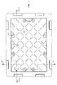
- Fig. 1 is a top plan view of a tray-like mould according to the invention;
- Fig. 2 is a bottom plan view of the tray-like mould;
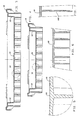
- Figs. 3 and 4 are cross-sectional views along the planes indicated by III-III and IV-IV in Fig. 1;
- Fig. 5 is an enlarged cross-sectional view of the detail shown encircled in Figures 3 and 4;
- Figs. 6 and 7 are cross-sectional views along the planes indicated by VI-VI and VII-VII in Fig. 2;
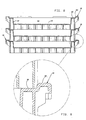
- Fig. 8 is a cross-sectional view of three tray-like moulds when in the stacked condition;
- Fig. 9 is an enlarged cross-sectional view of the detail shown encircled in Fig. 8.
-
- With reference first of all to Figures 1-4, a tray-like mould according to the present invention has a
bottom wall 10 and fourside walls 12 which define aninternal moulding cavity 14. - The outer surface of the
bottom wall 10 is provided with projecting stiffening ribs 16 (A, B and C), of which theribs 16A and 16B are arranged perpendicular to each other (namely parallel to theside walls 12 of the mould), as can be easily understood from Fig. 2, while theribs 16C are arranged diagonally. In this way the mould has a high mechanical strength and at the same time is sufficiently lightweight to allow handling thereof during the various processing steps. - The arrangement of the ribs is also so designed to allow the penetration of the forks of forklift trucks for handling operations. However, the outer edge also has a form which allows manual gripping.
- In fact, as can be readily seen from Figures 3 and 4, the
external edge 18 of the tray-like is suitably shaped so as to allow both stacking and the above mentioned gripping. - With reference to Figures 8 and 9, the first of these figures shows three tray-like moulds stacked on top of each other, while the second one shows a partially sectioned and enlarged detail of the stacked and centred arrangement of the tray-like moulds.
- In particular from Figures 8 and 9 it can be seen that the
edge 18 consists of twoportions portion 20 and is enclosed by theportion 22. - It is worth noting that, during manual stacking onto the last tray-like, a lid (which may also consist of an empty tray) for closing the
cavity 14 is provided onto the uppermost tray-like mould. - Fig. 5 shows a particular detail of the bottom of the tray according to Fig. 1. In predefined and equidistant positions along its own periphery, the
bottom wall 10 of the tray-like mould has adepression 20 with a height which is very small but sufficient to form in the final slab a plurality of projections that are able to act as supporting feet for the rough-formed slab when the latter is transferred (after the hardening step) to the stations for the subsequent processing step, in particular during the sizing step. - In the embodiment shown in Fig. 1, the
depressions 20 are eight in number, namely two on each side of thebottom wall 10 of the tray-like mould. From Fig. 1 it can also be seen that these depressed zones have a circular shape so that the resulting projections in the final rough-formed slab have the shape of true supporting feet. - Preferably the tray-like mould is obtained by injection-moulding from a suitable plastic material such as polyurethane or ABS resin having the desired technical characteristics.
- By way of conclusion, with the tray-like mould according to the invention the following advantages may be achieved:
- lightness
- rigidity
- low cost
- resistance to the action of atmospheric agents, in particularly to oxidation
- durability
- non-absorption of water
- impact resistance
- resistance to temperatures above room temperature
- In particular the ability of staking and of providing a sealing action against undesirable water evaporation, especially during the setting step of the mix, are to be appreciated.
- It is understood that mechanically equivalent modifications and variations are possible and may be envisaged within the coverage of the appended claims.
- In particular, modifications shall be expected as regards the arrangement of the reinforcing and stiffening ribs and the shape of the edges so as to allow stacking and simultaneous sealing of several tray-like moulds.
Claims (4)
- Tray-like mould for the manufacture of concrete slabs having a bottom wall (10) and a plurality of side walls (14) which is obtained from a plastic material with good mechanical strength properties and impermeable, so as to prevent the absorption of even a small amount of water from the concrete mix in contact with the said walls (10, 14), characterized in that it is provided at the outer surface of said bottom wall (10) with several stiffening ribs (16A, 16B, 16C) and is furthermore provided with a peripheral edge (18) shaped so as to allow several tray-like moulds to be stacked on top of each other in a steam-tight manner.
- Tray-like mould according to Claim 1, characterized in that its bottom wall (10) is provided with zones (20) which are depressed by a predefined amount so as to produce in the resulting slab a plurality of projections acting as supporting feet for the subsequent processing operations.
- Tray-like mould according to Claim 1, characterized in that said ribs are arranged parallel (16A, 16B) to the said perpendicular side walls (12) and diagonally (16C) thereto.
- Tray-like mould according to Claim 1, characterized in that said plastic material is chosen from polyurethane or ABS resin.
Applications Claiming Priority (2)
| Application Number | Priority Date | Filing Date | Title |
|---|---|---|---|
| ITTV000025U | 2000-05-30 | ||
| ITTV20000025 IT251479Y1 (en) | 2000-05-30 | 2000-05-30 | TRAY MOLD FOR THE MANUFACTURE OF CONGLOMERATE SHEETS |
Publications (2)
| Publication Number | Publication Date |
|---|---|
| EP1160064A1 true EP1160064A1 (en) | 2001-12-05 |
| EP1160064B1 EP1160064B1 (en) | 2006-03-08 |
Family
ID=11459789
Family Applications (1)
| Application Number | Title | Priority Date | Filing Date |
|---|---|---|---|
| EP20010112657 Expired - Lifetime EP1160064B1 (en) | 2000-05-30 | 2001-05-25 | Tray-like mould for the manufacture of concrete slabs |
Country Status (4)
| Country | Link |
|---|---|
| EP (1) | EP1160064B1 (en) |
| DE (1) | DE60117636T2 (en) |
| ES (1) | ES2257356T3 (en) |
| IT (1) | IT251479Y1 (en) |
Cited By (3)
| Publication number | Priority date | Publication date | Assignee | Title |
|---|---|---|---|---|
| ES2245854A1 (en) * | 2002-10-25 | 2006-01-16 | Luca Toncelli | Mould for a chipboard production system includes external reinforcement including bottom adjustable supports and peripheral ribs |
| WO2006045728A1 (en) | 2004-10-20 | 2006-05-04 | Luca Toncelli | Apparatus for distributing in a thin layer a mix based on agglomerate stone or ceramic material |
| CN110065143A (en) * | 2019-05-27 | 2019-07-30 | 宿迁市保祥重工有限公司 | A kind of concrete folding board mold |
Families Citing this family (2)
| Publication number | Priority date | Publication date | Assignee | Title |
|---|---|---|---|---|
| KR101910149B1 (en) | 2018-02-06 | 2018-10-19 | 주식회사 전진 | Mold for manufaturing slab and manufacturing method thereof |
| TWI731656B (en) * | 2020-04-21 | 2021-06-21 | 臺灣水泥股份有限公司 | Container and method for manufacturing the same |
Citations (5)
| Publication number | Priority date | Publication date | Assignee | Title |
|---|---|---|---|---|
| BE537141A (en) * | ||||
| DE2909491A1 (en) * | 1979-03-10 | 1980-09-11 | Guenther Reinhard | Mould for fine concrete parts - of foamed polystyrene and has stepped sides permitting stacking above castings |
| FR2469992A1 (en) * | 1979-11-20 | 1981-05-29 | Barbier Rene | One-piece plastics mould for plaster cladding slab - is sufficiently supple to deform and remain in one piece when releasing cast slab |
| EP0460331A1 (en) * | 1989-02-16 | 1991-12-11 | Jean Louis Desjoyaux | Element for forming slabs or kerbstones, in particular from concrete |
| WO1998058783A1 (en) * | 1997-06-23 | 1998-12-30 | Ayhan Babacan | Glass reinforced cement (grc) sheets/plates |
-
2000
- 2000-05-30 IT ITTV20000025 patent/IT251479Y1/en active
-
2001
- 2001-05-25 DE DE2001617636 patent/DE60117636T2/en not_active Expired - Fee Related
- 2001-05-25 EP EP20010112657 patent/EP1160064B1/en not_active Expired - Lifetime
- 2001-05-25 ES ES01112657T patent/ES2257356T3/en not_active Expired - Lifetime
Patent Citations (5)
| Publication number | Priority date | Publication date | Assignee | Title |
|---|---|---|---|---|
| BE537141A (en) * | ||||
| DE2909491A1 (en) * | 1979-03-10 | 1980-09-11 | Guenther Reinhard | Mould for fine concrete parts - of foamed polystyrene and has stepped sides permitting stacking above castings |
| FR2469992A1 (en) * | 1979-11-20 | 1981-05-29 | Barbier Rene | One-piece plastics mould for plaster cladding slab - is sufficiently supple to deform and remain in one piece when releasing cast slab |
| EP0460331A1 (en) * | 1989-02-16 | 1991-12-11 | Jean Louis Desjoyaux | Element for forming slabs or kerbstones, in particular from concrete |
| WO1998058783A1 (en) * | 1997-06-23 | 1998-12-30 | Ayhan Babacan | Glass reinforced cement (grc) sheets/plates |
Cited By (4)
| Publication number | Priority date | Publication date | Assignee | Title |
|---|---|---|---|---|
| ES2245854A1 (en) * | 2002-10-25 | 2006-01-16 | Luca Toncelli | Mould for a chipboard production system includes external reinforcement including bottom adjustable supports and peripheral ribs |
| ES2245854B1 (en) * | 2002-10-25 | 2007-03-16 | Luca Toncelli | TRAY MOLD FOR THE MANUFACTURED MANUFACTURED IN THE FORM OF PLATE OR PANEL PANEL. |
| WO2006045728A1 (en) | 2004-10-20 | 2006-05-04 | Luca Toncelli | Apparatus for distributing in a thin layer a mix based on agglomerate stone or ceramic material |
| CN110065143A (en) * | 2019-05-27 | 2019-07-30 | 宿迁市保祥重工有限公司 | A kind of concrete folding board mold |
Also Published As
| Publication number | Publication date |
|---|---|
| IT251479Y1 (en) | 2003-11-19 |
| DE60117636T2 (en) | 2007-01-18 |
| ITTV20000025U1 (en) | 2001-11-30 |
| EP1160064B1 (en) | 2006-03-08 |
| DE60117636D1 (en) | 2006-05-04 |
| ES2257356T3 (en) | 2006-08-01 |
Similar Documents
| Publication | Publication Date | Title |
|---|---|---|
| AU2012100336A6 (en) | Method and apparatus for moulding | |
| US7516558B2 (en) | Cement-based tile-setting spacers and related process | |
| US4075380A (en) | Construction panels | |
| EP1160064B1 (en) | Tray-like mould for the manufacture of concrete slabs | |
| US9038346B1 (en) | Segmental retaining wall corner block and wall corner comprised of corner blocks | |
| WO1992007695A1 (en) | A method of producing concrete elements | |
| RU2087308C1 (en) | Method of manufacture of interior-facing gypsum products, mould for manufacture of interior-facing products | |
| US3496264A (en) | Method for producing decorative tile | |
| KR20100007324U (en) | The production apparatus for clay vessel | |
| WO2006063940A1 (en) | Rubber-based mould use for the production of slabs of agglomerated stone material and method for the manufacture thereof | |
| WO2004070134A1 (en) | Composite tile or panel with a cement agglomerated base | |
| US20030147986A1 (en) | Press and mould for precast cementitious article | |
| RU2358862C2 (en) | Tray for vibration compaction of paving tiles with relief pattern | |
| JP3700145B2 (en) | Manufacturing method of reinforced building materials with charcoal | |
| GB2259271A (en) | Casting blocks | |
| KR20100063587A (en) | The production apparatus and method of clay container | |
| KR20100006114U (en) | The production apparatus for clay vessel | |
| JP2541910B2 (en) | Pallet type manufacturing method | |
| SU1712324A1 (en) | Mld for making slabs | |
| CA1109239A (en) | Moulds, countermoulds and pallets or trays for the manufacture of bricks or building blocks with male- female fitting | |
| KR20100082267A (en) | The production apparatus for clay vessel | |
| JPH0343042B2 (en) | ||
| JP2001353709A (en) | Mold for ceramics architectural board and method for manufacturing ceramics architectural board using the mold | |
| RU2007132437A (en) | METHODS AND DEVICE FOR MANUFACTURING A FIREPLACE, CASTING FORM AND FIREPLACE | |
| GB2294959A (en) | A facing quoin |
Legal Events
| Date | Code | Title | Description |
|---|---|---|---|
| PUAI | Public reference made under article 153(3) epc to a published international application that has entered the european phase |
Free format text: ORIGINAL CODE: 0009012 |
|
| AK | Designated contracting states |
Kind code of ref document: A1 Designated state(s): DE ES IT Kind code of ref document: A1 Designated state(s): AT BE CH CY DE DK ES FI FR GB GR IE IT LI LU MC NL PT SE TR |
|
| AX | Request for extension of the european patent |
Free format text: AL;LT;LV;MK;RO;SI |
|
| 17P | Request for examination filed |
Effective date: 20020508 |
|
| AKX | Designation fees paid |
Free format text: AT BE CH LI |
|
| RBV | Designated contracting states (corrected) |
Designated state(s): DE ES IT |
|
| REG | Reference to a national code |
Ref country code: DE Ref legal event code: 8566 |
|
| 17Q | First examination report despatched |
Effective date: 20041001 |
|
| GRAP | Despatch of communication of intention to grant a patent |
Free format text: ORIGINAL CODE: EPIDOSNIGR1 |
|
| GRAS | Grant fee paid |
Free format text: ORIGINAL CODE: EPIDOSNIGR3 |
|
| GRAA | (expected) grant |
Free format text: ORIGINAL CODE: 0009210 |
|
| AK | Designated contracting states |
Kind code of ref document: B1 Designated state(s): DE ES IT |
|
| REF | Corresponds to: |
Ref document number: 60117636 Country of ref document: DE Date of ref document: 20060504 Kind code of ref document: P |
|
| PGFP | Annual fee paid to national office [announced via postgrant information from national office to epo] |
Ref country code: IT Payment date: 20060531 Year of fee payment: 6 |
|
| REG | Reference to a national code |
Ref country code: ES Ref legal event code: FG2A Ref document number: 2257356 Country of ref document: ES Kind code of ref document: T3 |
|
| PLBE | No opposition filed within time limit |
Free format text: ORIGINAL CODE: 0009261 |
|
| STAA | Information on the status of an ep patent application or granted ep patent |
Free format text: STATUS: NO OPPOSITION FILED WITHIN TIME LIMIT |
|
| 26N | No opposition filed |
Effective date: 20061211 |
|
| PGFP | Annual fee paid to national office [announced via postgrant information from national office to epo] |
Ref country code: DE Payment date: 20080514 Year of fee payment: 8 |
|
| PG25 | Lapsed in a contracting state [announced via postgrant information from national office to epo] |
Ref country code: IT Free format text: LAPSE BECAUSE OF NON-PAYMENT OF DUE FEES Effective date: 20070525 |
|
| PG25 | Lapsed in a contracting state [announced via postgrant information from national office to epo] |
Ref country code: DE Free format text: LAPSE BECAUSE OF NON-PAYMENT OF DUE FEES Effective date: 20091201 |
|
| PGFP | Annual fee paid to national office [announced via postgrant information from national office to epo] |
Ref country code: ES Payment date: 20200602 Year of fee payment: 20 |
|
| REG | Reference to a national code |
Ref country code: ES Ref legal event code: FD2A Effective date: 20210901 |
|
| PG25 | Lapsed in a contracting state [announced via postgrant information from national office to epo] |
Ref country code: ES Free format text: LAPSE BECAUSE OF EXPIRATION OF PROTECTION Effective date: 20210526 |