EP1160034A2 - Inside diameter machining method - Google Patents
Inside diameter machining method Download PDFInfo
- Publication number
- EP1160034A2 EP1160034A2 EP00118948A EP00118948A EP1160034A2 EP 1160034 A2 EP1160034 A2 EP 1160034A2 EP 00118948 A EP00118948 A EP 00118948A EP 00118948 A EP00118948 A EP 00118948A EP 1160034 A2 EP1160034 A2 EP 1160034A2
- Authority
- EP
- European Patent Office
- Prior art keywords
- tool
- workpiece
- machining
- turning
- turning tool
- Prior art date
- Legal status (The legal status is an assumption and is not a legal conclusion. Google has not performed a legal analysis and makes no representation as to the accuracy of the status listed.)
- Withdrawn
Links
Images


Classifications
-
- B—PERFORMING OPERATIONS; TRANSPORTING
- B23—MACHINE TOOLS; METAL-WORKING NOT OTHERWISE PROVIDED FOR
- B23B—TURNING; BORING
- B23B29/00—Holders for non-rotary cutting tools; Boring bars or boring heads; Accessories for tool holders
- B23B29/02—Boring bars
-
- B—PERFORMING OPERATIONS; TRANSPORTING
- B23—MACHINE TOOLS; METAL-WORKING NOT OTHERWISE PROVIDED FOR
- B23B—TURNING; BORING
- B23B5/00—Turning-machines or devices specially adapted for particular work; Accessories specially adapted therefor
- B23B5/36—Turning-machines or devices specially adapted for particular work; Accessories specially adapted therefor for turning specially-shaped surfaces by making use of relative movement of the tool and work produced by geometrical mechanisms, i.e. forming-lathes
- B23B5/40—Turning-machines or devices specially adapted for particular work; Accessories specially adapted therefor for turning specially-shaped surfaces by making use of relative movement of the tool and work produced by geometrical mechanisms, i.e. forming-lathes for turning spherical surfaces inside or outside
-
- Y—GENERAL TAGGING OF NEW TECHNOLOGICAL DEVELOPMENTS; GENERAL TAGGING OF CROSS-SECTIONAL TECHNOLOGIES SPANNING OVER SEVERAL SECTIONS OF THE IPC; TECHNICAL SUBJECTS COVERED BY FORMER USPC CROSS-REFERENCE ART COLLECTIONS [XRACs] AND DIGESTS
- Y10—TECHNICAL SUBJECTS COVERED BY FORMER USPC
- Y10T—TECHNICAL SUBJECTS COVERED BY FORMER US CLASSIFICATION
- Y10T82/00—Turning
- Y10T82/10—Process of turning
-
- Y—GENERAL TAGGING OF NEW TECHNOLOGICAL DEVELOPMENTS; GENERAL TAGGING OF CROSS-SECTIONAL TECHNOLOGIES SPANNING OVER SEVERAL SECTIONS OF THE IPC; TECHNICAL SUBJECTS COVERED BY FORMER USPC CROSS-REFERENCE ART COLLECTIONS [XRACs] AND DIGESTS
- Y10—TECHNICAL SUBJECTS COVERED BY FORMER USPC
- Y10T—TECHNICAL SUBJECTS COVERED BY FORMER US CLASSIFICATION
- Y10T82/00—Turning
- Y10T82/12—Radially moving rotating tool inside bore
- Y10T82/122—Forming non-circular bore
-
- Y—GENERAL TAGGING OF NEW TECHNOLOGICAL DEVELOPMENTS; GENERAL TAGGING OF CROSS-SECTIONAL TECHNOLOGIES SPANNING OVER SEVERAL SECTIONS OF THE IPC; TECHNICAL SUBJECTS COVERED BY FORMER USPC CROSS-REFERENCE ART COLLECTIONS [XRACs] AND DIGESTS
- Y10—TECHNICAL SUBJECTS COVERED BY FORMER USPC
- Y10T—TECHNICAL SUBJECTS COVERED BY FORMER US CLASSIFICATION
- Y10T82/00—Turning
- Y10T82/12—Radially moving rotating tool inside bore
- Y10T82/125—Tool simultaneously moving axially
- Y10T82/128—Pivoted to tool-carrier
-
- Y—GENERAL TAGGING OF NEW TECHNOLOGICAL DEVELOPMENTS; GENERAL TAGGING OF CROSS-SECTIONAL TECHNOLOGIES SPANNING OVER SEVERAL SECTIONS OF THE IPC; TECHNICAL SUBJECTS COVERED BY FORMER USPC CROSS-REFERENCE ART COLLECTIONS [XRACs] AND DIGESTS
- Y10—TECHNICAL SUBJECTS COVERED BY FORMER USPC
- Y10T—TECHNICAL SUBJECTS COVERED BY FORMER US CLASSIFICATION
- Y10T82/00—Turning
- Y10T82/16—Severing or cut-off
- Y10T82/16426—Infeed means
- Y10T82/16639—Tool within work
Definitions
- This invention relates to an inside diameter machining method suitable for turning machining in order to form a machining hole, such as a bag hole having the entrance of a hole smaller than the machining diameter of its inside.
- the object of the present invention is to provide inside diameter machining method capable of performing bag hole machining using a normal cutting tool, such as a cutting tool for boring, without using formed tool, taking the above-mentioned circumstances into consideration.
- the invention of claim 1 is inside diameter machining method in boring machining for machining inside a workpiece using a turning tool having cutting portion at an end portion of its main body in the shape of a bar, comprising:
- the cutting portion of the turning tool can be positioned at the portion to be machined of the inside of the workpiece with no interference between the turning tool and the workpiece. Then, the machining for forming machining hole, such as a bag hole, is possible without using a formed tool as a turning tool.
- turning tool is held by turning tool holding means provided with a spindle side for rotating and driving said workpiece at the time of machining of the inside of said workpiece so as to prevent chatter of the turning tool.
- the top end portion of said turning tool is inserted into said tool insertion hole, subsequently the main body portion of the turning tool continuing to the top end portion is inserted, and furthermore the main body portion of the turning tool continuing to the inserted main body portion is inserted when the turning tool is inserted into said workpiece.
- the turning tool is gradually inserted into the tool insertion hole along the whole length of the tool body, starting the top end portion thereof. Then, the turning tool can pass through the tool insertion hole of the workpiece, making use of the portion which section is the smallest, and the occurrence of the interference between the workpiece and the turning tool can be effectively prevented.
- a machine tool 1 has a spindle 2 rotatably and drivably provided around an axial center CT parallel to Z-axis, as shown in Fig.1.
- a chuck 3 is rotatably provided with the spindle 2 around the axial center CT together with the spindle 2.
- a plurality of claws 3a are movably and drivably provided with the chuck 3 in the direction as shown by arrows M and L which is the radial direction orthogonal to the axial center CT (the Z-axis).
- a workpiece 5 on which boring machining is performed is held by the claws 3a corresponding the center CL of the workpiece with the axial center CT of the spindle.
- a through hole 2a is formed in the spindle 2 in the direction as shown by arrows J and K which is the axial center CT direction.
- a chatter prevention bar 6 is provided with the through hole 2a, being free to move and drive in the direction as shown by the arrows J and K by a cylinder driving unit which is not shown.
- a pusher 6a is supported by the top end portion of a main body 6b of the chatter prevention bar 6, being relatively rotatable with respect to the main body 6b (it is not always relatively rotatable, but the pusher 6a may be fixed with respect to the main body 6b).
- An engagement slot 6c which section has V-character shape is formed on the top end portion of the pusher 6a in the direction as shown by the arrows M and L which is orthogonal direction with respect to the axial center CT.
- a hole 6e is formed on the main body 6b of the chatter prevention bar 6 in the axial center CT direction, and a coiled spring 6d is provided with the hole 6e so as to shrink.
- a tool holder 7 installed on a tool rest (not shown) is movably and drivably provided in the direction as shown by the arrows J and K which is the Z-axis direction and in the X-axis direction orthogonal to the Z-axis direction, that is, in the direction as shown by the arrows N and P.
- the tool holder 7 is provided being free to rotate, position and drive in the direction as shown by the arrows Q and R with a predetermined axis CT2 orthogonal to the paper, that is, the Y-axis orthogonal to the X-axis and the Z-axis as its center, that is, in the B-axis direction.
- a cutting tool 9 for boring is attachably and detachably installed on the tool holder 7.
- the cutting tool 9 has a main body 9a formed such that the top end of a bar member having the diameter D3 is bent in the shape of key.
- a projection 9b having the shape corresponding to the engagement slot 6c of the chatter prevention bar 6 in its section is formed at the top end portion of the main body 9a.
- the top end of the main body 9a is bent on the upper hand of Fig.1, and a chip 9c is installed on its end.
- the workpiece 5 installed on the chuck 3 through the claw 3a has a main body 5a formed in almost sphere shape as a whole.
- through holes 5b, 5c which diameter is D2 are formed, corresponding the workpiece center CL with its center.
- An inside space 5d in the shape of almost sphere is formed inside the main body 5a.
- Inner cylindrical faces 5e on which turning machining is performed, which diameter is D1 are formed on the lower and upper hands of the figure facing the inside space 5d of the main body 5a.
- the diameter D2 of the through hole 5c is bigger than the diameter D3 of the bar member comprising the main body 5a of the cutting tool 9.
- the diameter D1 of the inner cylindrical face 5e is bigger than the diameter D2 of the through hole 5c, then it is a so-called bag hole.
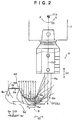
- the machine tool 1 has the above-mentioned structure. Then, in order to perform inside diameter machining on the inner cylindrical face 5e of the workpiece 5 as shown by the hatching of Fig.1, programming is performed in such a manner that the chip 9c which is on the top end of the cutting tool 9 for boring held by the tool holder 7 is positioned at a predetermined machining start point H (see Fig.2) of the inner cylindrical face 5e of the workpiece 5 with a numerically controlled machine of the machine tool 1 (not shown).
- the tool pass is instructed in the program as shown in Figs.2 and 3 in such a manner that the axial center CL1 of the cutting tool 9 is positioned in the direction parallel to the X-axis direction, and in this state, the tool holder 7 is moved and driven in the X-axis direction (in the direction as shown by the arrows N and P) and in the Z-axis direction (in the direction as shown by the arrows J and K), and at the same time, is rotated and driven in the B-axis direction (in the direction as shown by the arrows Q and R) which is the rotational direction with the Y-axis as its center, which is orthogonal direction with respect to the X-axis and the Z-axis so as to position a top end 9d of the chip 9c at the machining start point H via the points A, B, C, D, E, F and G from the waiting point S, as shown in Fig.2.
- the tool rest may be moved in the Y-axis direction together
- the cutting tool 9 is entered into the through hole 5c of the workpiece 5 with no interference with the workpiece 5, rotating the whole in the right direction of Fig.2 such that the bar-shaped main body 9a is along the bent shape of the main body 9a so as to position the top end of the chip 9c at a predetermined machining start point H, as shown in Fig.2. Since the diameter D2 of the through hole 5c of the workpiece 5 is bigger than the diameter D3 of the main body 9a of the cutting tool 9, the interference between the cutting tool 9 and the workpiece 5 can be prevented by entering the cutting tool 9 into the through hole 5c along the bent shape of the cutting tool 9.
- Such a program can be easily composed by using a known teaching.
- the spindle 2 is rotated and driven so as to rotate the workpiece 5 with the axial center CT as its center through the chuck 3.
- the chip 9c portion of the top end portion of the cutting tool 9 is faced on the right hand of the Fig.2 of the through hole 5c (waiting position S) by the above-mentioned program.
- the chip 9c is moved in the direction as shown by the arrow J of the figure, and the top end of the chip 9c is inserted into the top end portion of the right hand of the figure of the through hole 5c (the points A and B).
- the top end of the chip 9c is gradually moved in the direction as shown by the arrow J so as to enter the top end portion of the cutting tool 9 into the through hole 5c.
- the main body of the cutting tool 9 is gradually rotated in the direction as shown by the arrow R so as to enter a bent portion 9e into the through hole 5c with no interference between the bent portion 9e of the top end of the cutting tool body 9a and the workpiece 5 (the points C, D, E, F, and G).
- the cutting tool 9 is gradually inserted into the inside space 5d from the through hole 5c, starting from its top end portion in such a manner that by rotating the cutting tool 9 in the direction as shown by the arrow R, while being moved a predetermined distance in the direction as shown by the arrow J in this way, the top end portion of the main body 9a of the cutting tool 9 is inserted into the through hole 5c, the main body 9a portion of the cutting tool 9 continuing to the top end portion is inserted into the through hole 5c, and furthermore, the main body portion of the cutting tool 9 continuing to the inserted main body portion is inserted into the through hole 5c.
- the top end 9d of the chip 9c is inserted into the inside space 5d from the through hole 5c of the workpiece 5 so as to position at a predetermined machining starting point H.
- the cutting tool 9 can pass the through hole 5c of the workpiece 5, making use of the portion which section is the smallest, and occurrence of interference between the workpiece 5 and the cutting tool 9 can be effectively prevented.
- chatter prevention bar 6 in the spindle 2 is projected and driven in the direction as shown by the arrow K of Fig.1 through a cylinder driving unit which is not shown and the coiled spring 6d so as to project the pusher 6a of the top end inside the inside space 5d of the workpiece 5.
- the top end of the pusher 6a and the top end of the cutting tool 9 advanced into the workpiece 5 are abutted to each other, the projection 9b of the top end of the cutting tool 9 is inserted in and engaged with the engagement slot 6c of the pusher 6a in the rotating state, and furthermore, the pusher 6a is relatively pushed and moved in the direction as shown by the arrow J with respect to the coiled spring 6d against the elasticity of the coiled spring 6d by pushing the chatter prevention bar 6 by the cylinder driving unit through the coiled spring 6d in the direction as shown by the arrow K.
- the cutting tool 9 positioned at the machining starting point H becomes to be pressed state in the direction as shown by the arrow K by a predetermined pressing force caused by the elasticity of the coiled spring 6d of the chatter prevention bar 6 by engaging the projection 9b of the cutting tool 9 with the engagement slot 6c of the chatter prevention bar 6.
- the cutting tool 9 is properly moved in the X-axis direction and in the Z-axis direction, similar to normal boring machining, and the top end 9d of the chip 9c moved to a machining finish point I as shown in Fig.2.
- turning machining is performed on the inner cylindrical face 5e so as to cut and form a bearing surface 5f by machining and removing the hatching portion of the figure.
- chatter attendant on the machining of the bearing surface 5f is effectively restricted and accurate machining face is formed since the top end of the cutting tool 9 is in the state pressed in the direction as shown by the arrow K by the chatter prevention bar 6, as mentioned before. Since the chatter prevention bar 6 is movably held by the coiled spring 6d in the direction as shown by the arrows J and K in the spindle 2 as mentioned before, the engagement state between the cutting tool 9 and the chatter prevention bar 6 is held even if the cutting tool 9 is moved in the direction as shown by the arrows J and K at the time of machining. Then, the occurrence of chatter of the cutting tool 9 is restricted.
- the chatter prevention bar 6 is retracted in the direction as shown by the arrow J of Fig.1 so as to release the engagement state between the cutting tool 9 and the chatter prevention bar 6.
- the tool holder 7 is rotated and driven in the B-axis direction (in the direction as shown by the arrows Q and R) while being moved and driven in the X-axis direction (in the direction as shown by the arrows J and K) and in the Z-axis direction (in the direction as shown by the arrows N and P) so as to move the top end 9d of the chip 9c to a waiting point S via the points I, G, F, E, D, C, B and A as shown in Fig.2 in the order opposite to the before-mentioned. Then, the machining on the workpiece 5 finishes.
- the above-mentioned embodiment refers to the case where programming is performed by teaching or so in advance when the turning tool, such as the cutting tool 9, is moved in the X-axis direction, in the Z-axis direction and in the B-axis direction from the tool insertion hole, such as the through hole 5c of the workpiece to be machined along the tool shape of the turning tool so as to position the machining portion, such as the top end of the chip 9c at the portion to be machined, such as the inner cylindrical face 5e inside the workpiece.
- the turning tool may be positioned at the portion to be machined by moving the turning tool in the X-axis direction, in the Z-axis direction (in the Y-axis direction, if necessary) and in the B-axis direction from the tool insertion hole, such as the through hole 5c of the workpiece along the tool shape of the turning tool so as not to interfere the turning tool and the workpiece with each other, being judged the interference state between the turning tool and the workpiece by a numerically controlled unit of a machine tool, in addition to the above-mentioned method.
Landscapes
- Engineering & Computer Science (AREA)
- Mechanical Engineering (AREA)
- Drilling And Boring (AREA)
- Cutting Tools, Boring Holders, And Turrets (AREA)
- Turning (AREA)
- Milling Processes (AREA)
Abstract
Description
Claims (3)
- Inside diameter machining method in boring machining for machining inside a workpiece using a turning tool having cutting portion at an end portion of its main body in the shape of a bar, comprising:at the time of turning machining on the machining hole where the size of a tool insertion hole of the workpiece into which the turning tool is inserted is smaller than the machining diameter of the portion to be machined inside the workpiece,moving said turning tool in a first axial direction and in a second axial direction orthogonal to each other and in a rotational direction with a third axial direction orthogonal to both first and second axial directions as its center from said tool insertion hole of a workpiece to be machined along tool shape of said turning tool so as to position cutting portion of said turning tool at the portion to be machined inside the workpiece; andstarting turning machining on the portion to be machined of said workpiece in the above-mentioned state.
- The inside diameter machining method as set forth in claim 1, wherein said turning tool is held by turning tool holding means provided with a spindle side for rotating and driving said workpiece at the time of machining of the inside of said workpiece so as to prevent chatter of the turning tool.
- The inside diameter machining method as set forth in claim 1, wherein firstly, the top end portion of said turning tool is inserted into said tool insertion hole, subsequently the main body portion of the turning tool continuing to the top end portion is inserted, and furthermore the main body portion of the turning tool continuing to the inserted main body portion is inserted when the turning tool is inserted into said workpiece.
Applications Claiming Priority (2)
| Application Number | Priority Date | Filing Date | Title |
|---|---|---|---|
| JP2000162607A JP2001341013A (en) | 2000-05-31 | 2000-05-31 | Inner diameter working method |
| JP2000162607 | 2000-05-31 |
Publications (2)
| Publication Number | Publication Date |
|---|---|
| EP1160034A2 true EP1160034A2 (en) | 2001-12-05 |
| EP1160034A3 EP1160034A3 (en) | 2003-11-19 |
Family
ID=18666486
Family Applications (1)
| Application Number | Title | Priority Date | Filing Date |
|---|---|---|---|
| EP00118948A Withdrawn EP1160034A3 (en) | 2000-05-31 | 2000-09-01 | Inside diameter machining method |
Country Status (6)
| Country | Link |
|---|---|
| US (1) | US6578453B1 (en) |
| EP (1) | EP1160034A3 (en) |
| JP (1) | JP2001341013A (en) |
| KR (1) | KR20010109482A (en) |
| CN (1) | CN1210126C (en) |
| TW (1) | TW501960B (en) |
Cited By (3)
| Publication number | Priority date | Publication date | Assignee | Title |
|---|---|---|---|---|
| CN106077707A (en) * | 2016-06-28 | 2016-11-09 | 梧州奥卡光学仪器有限公司 | Microscope zoom body car hole method |
| CN113399685A (en) * | 2021-07-23 | 2021-09-17 | 上海交通大学 | Double-swing diamond cutter cutting device and cutting method |
| EP3789141A4 (en) * | 2018-05-01 | 2022-01-26 | Haru Technique Laboratory Inc. | DIFFERENTIAL CASE MACHINING MACHINE |
Families Citing this family (19)
| Publication number | Priority date | Publication date | Assignee | Title |
|---|---|---|---|---|
| JP4572133B2 (en) * | 2005-03-28 | 2010-10-27 | 富士機械製造株式会社 | Internal processing equipment for hollow workpieces |
| TWI421660B (en) * | 2005-07-08 | 2014-01-01 | Entegris Inc | Chemically inert flow controller with non-contaminating body |
| JP4611833B2 (en) * | 2005-07-27 | 2011-01-12 | アイシン高丘株式会社 | Internal processing method and internal processing apparatus for differential case |
| JP4621569B2 (en) * | 2005-09-13 | 2011-01-26 | 中村留精密工業株式会社 | Machining method of spindle crossing inner circumference in lathe |
| DE102006011300B3 (en) * | 2006-03-11 | 2007-09-27 | Felsomat Gmbh & Co. Kg | Turning machine for motor vehicle transmission, has tool blade provided at holder and comprising circular arc-shaped section, where radius of curvature of section corresponds to radial distance of blade from swivel axis |
| JP4724026B2 (en) * | 2006-03-22 | 2011-07-13 | 株式会社三栄水栓製作所 | Eccentric tube and manufacturing method thereof |
| CN100391665C (en) * | 2006-07-21 | 2008-06-04 | 上海汽车股份有限公司 | Cutting method of wet hard turning of steel parts after quenching heat treatment |
| JP5557587B2 (en) * | 2010-04-28 | 2014-07-23 | 富士機械製造株式会社 | Internal processing equipment for hollow workpieces |
| TWI422446B (en) * | 2011-02-01 | 2014-01-11 | China Steel Corp | An annular deep hole processing apparatus and a method of machining the inner wall of the workpiece |
| CN102489731B (en) * | 2011-11-30 | 2014-02-12 | 中国石油集团川庆钻探工程有限公司长庆钻井总公司 | Combined maintenance tool for hydraulic tong shell |
| CN102615293B (en) * | 2012-04-25 | 2013-11-27 | 江西江铃底盘股份有限公司 | Method for machining spherical surface of inner cavity of integral differential case of automobile |
| CN104588683A (en) * | 2014-12-09 | 2015-05-06 | 齐齐哈尔雷昂重工机械制造有限责任公司 | Valve body segment inner cone hole machining process |
| US20160207116A1 (en) * | 2015-01-20 | 2016-07-21 | United Technologies Corporation | Method to machine deep features using a lathe |
| KR20170129163A (en) | 2015-02-24 | 2017-11-24 | 반두리트 게엠베하 하르트메탈 운트 디아만트베르크초이그 | Device, method and cutting plate for machining a rotary work piece |
| DE102016109036A1 (en) | 2016-05-17 | 2017-11-23 | Vandurit GmbH Hartmetall und Diamantwerkzeuge | Tool swivel unit for a lathe |
| JP6322351B1 (en) | 2017-12-01 | 2018-05-09 | 株式会社ハル技術研究所 | Cutting tool for differential case processing, differential case processing machine, and differential case processing method |
| US20200331080A1 (en) * | 2019-04-16 | 2020-10-22 | United Technologies Corporation | Lockout for deep reach machining tool |
| CN113414554B (en) * | 2021-07-07 | 2023-06-02 | 山东明兴金属科技股份有限公司 | Machining process and tool for large-diameter thin-wall ring workpieces |
| WO2023181638A1 (en) * | 2022-03-23 | 2023-09-28 | 村田機械株式会社 | Machine tool |
Family Cites Families (9)
| Publication number | Priority date | Publication date | Assignee | Title |
|---|---|---|---|---|
| JPH0229442B2 (en) * | 1982-03-10 | 1990-06-29 | Toyoda Machine Works Ltd | KYUMENKAKOSOCHI |
| JPS61252002A (en) * | 1985-04-30 | 1986-11-10 | Mazda Motor Corp | Spherical surface machining device |
| US4750392A (en) * | 1987-03-12 | 1988-06-14 | Kwangil Hong | Adjustable tool holder |
| US4945792A (en) * | 1988-01-21 | 1990-08-07 | Cameron Iron Works Usa, Inc. | Boring tool for machining the interior of narrow neck casing |
| US5086676A (en) * | 1990-07-11 | 1992-02-11 | J. P. Tool, Inc. | Method and apparatus for machining a differential carrier |
| US5141063A (en) * | 1990-08-08 | 1992-08-25 | Quesenbury Jimmy B | Restriction enhancement drill |
| US5159862A (en) * | 1991-01-18 | 1992-11-03 | Dresser-Rand Company | Method and apparatus for machining the inside surface of a closed hollow casing |
| PL179956B1 (en) * | 1995-03-03 | 2000-11-30 | Komet Praezisionswerkzeuge Robert Breuning Gmbh | Actuating system in particular for positioning machining tools as well as tool head actuated thereby |
| JPH11151601A (en) * | 1997-11-20 | 1999-06-08 | Eguro:Kk | Machining method of spherical surface in NC lathe |
-
2000
- 2000-05-31 JP JP2000162607A patent/JP2001341013A/en active Pending
- 2000-08-31 US US09/651,958 patent/US6578453B1/en not_active Expired - Fee Related
- 2000-09-01 EP EP00118948A patent/EP1160034A3/en not_active Withdrawn
-
2001
- 2001-05-22 TW TW090112230A patent/TW501960B/en not_active IP Right Cessation
- 2001-05-30 CN CNB011193379A patent/CN1210126C/en not_active Expired - Fee Related
- 2001-05-30 KR KR1020010029952A patent/KR20010109482A/en not_active Ceased
Cited By (4)
| Publication number | Priority date | Publication date | Assignee | Title |
|---|---|---|---|---|
| CN106077707A (en) * | 2016-06-28 | 2016-11-09 | 梧州奥卡光学仪器有限公司 | Microscope zoom body car hole method |
| EP3789141A4 (en) * | 2018-05-01 | 2022-01-26 | Haru Technique Laboratory Inc. | DIFFERENTIAL CASE MACHINING MACHINE |
| US11759900B2 (en) | 2018-05-01 | 2023-09-19 | Haru Technique Laboratory Inc. | Machining apparatus for differential case |
| CN113399685A (en) * | 2021-07-23 | 2021-09-17 | 上海交通大学 | Double-swing diamond cutter cutting device and cutting method |
Also Published As
| Publication number | Publication date |
|---|---|
| CN1326835A (en) | 2001-12-19 |
| US6578453B1 (en) | 2003-06-17 |
| JP2001341013A (en) | 2001-12-11 |
| TW501960B (en) | 2002-09-11 |
| KR20010109482A (en) | 2001-12-10 |
| EP1160034A3 (en) | 2003-11-19 |
| CN1210126C (en) | 2005-07-13 |
Similar Documents
| Publication | Publication Date | Title |
|---|---|---|
| US6578453B1 (en) | Inside diameter machining method | |
| US6865789B2 (en) | Tool holder for turret lathe | |
| US7736101B2 (en) | Guided rotary file | |
| EP1375064A1 (en) | Turret for turret lathe | |
| JP2007030101A (en) | Method and device for machining inner surface of differential case | |
| JPH11129116A (en) | Reamers and their use | |
| EP1166929B1 (en) | Combination tool | |
| JP2008264937A (en) | Polygon processing apparatus and polygon processing method | |
| JP2002205233A (en) | Claw member for chuck mechanism and method of manufacturing the same | |
| JP4426407B2 (en) | Cutting device | |
| JP2004042198A (en) | Jig for finishing operations of precision casting | |
| JPH11239909A (en) | Deburring method and device thereof | |
| JP2011110667A (en) | Deburring tool and deburring method | |
| JPH11333603A (en) | Composite rotary tool | |
| Kim et al. | A new deburring tool for intersecting holes | |
| JPH05337722A (en) | Rotary tool | |
| JP3978010B2 (en) | Thread deburring tool | |
| JP2001353611A (en) | Milling tools | |
| JP2003200302A (en) | Working method for eccentric workpiece in two-spindle opposed lathe | |
| JPH0947901A (en) | Resin bellows processing method and processing apparatus thereof | |
| JPH069812U (en) | Chamferable drill | |
| JP2009083071A (en) | Sheet surface machining tool, sheet surface machining method, and injector manufacturing method using the sheet surface machining tool | |
| JPH0115445Y2 (en) | ||
| JP4714625B2 (en) | Cutting equipment | |
| JP5112952B2 (en) | NC turret lathe |
Legal Events
| Date | Code | Title | Description |
|---|---|---|---|
| PUAI | Public reference made under article 153(3) epc to a published international application that has entered the european phase |
Free format text: ORIGINAL CODE: 0009012 |
|
| AK | Designated contracting states |
Kind code of ref document: A2 Designated state(s): AT BE CH CY DE DK ES FI FR GB GR IE IT LI LU MC NL PT SE |
|
| AX | Request for extension of the european patent |
Free format text: AL;LT;LV;MK;RO;SI |
|
| PUAL | Search report despatched |
Free format text: ORIGINAL CODE: 0009013 |
|
| AK | Designated contracting states |
Kind code of ref document: A3 Designated state(s): AT BE CH CY DE DK ES FI FR GB GR IE IT LI LU MC NL PT SE |
|
| AX | Request for extension of the european patent |
Extension state: AL LT LV MK RO SI |
|
| 17P | Request for examination filed |
Effective date: 20040519 |
|
| AKX | Designation fees paid |
Designated state(s): DE FR GB IT |
|
| 17Q | First examination report despatched |
Effective date: 20050330 |
|
| STAA | Information on the status of an ep patent application or granted ep patent |
Free format text: STATUS: THE APPLICATION IS DEEMED TO BE WITHDRAWN |
|
| 18D | Application deemed to be withdrawn |
Effective date: 20050810 |