EP1158781A2 - Horizontal deflection circuit and television receiver - Google Patents
Horizontal deflection circuit and television receiver Download PDFInfo
- Publication number
- EP1158781A2 EP1158781A2 EP01304488A EP01304488A EP1158781A2 EP 1158781 A2 EP1158781 A2 EP 1158781A2 EP 01304488 A EP01304488 A EP 01304488A EP 01304488 A EP01304488 A EP 01304488A EP 1158781 A2 EP1158781 A2 EP 1158781A2
- Authority
- EP
- European Patent Office
- Prior art keywords
- horizontal
- digital
- vertical
- video signal
- signal
- Prior art date
- Legal status (The legal status is an assumption and is not a legal conclusion. Google has not performed a legal analysis and makes no representation as to the accuracy of the status listed.)
- Withdrawn
Links
Images



Classifications
-
- H—ELECTRICITY
- H04—ELECTRIC COMMUNICATION TECHNIQUE
- H04N—PICTORIAL COMMUNICATION, e.g. TELEVISION
- H04N5/00—Details of television systems
- H04N5/63—Generation or supply of power specially adapted for television receivers
-
- H—ELECTRICITY
- H04—ELECTRIC COMMUNICATION TECHNIQUE
- H04N—PICTORIAL COMMUNICATION, e.g. TELEVISION
- H04N3/00—Scanning details of television systems; Combination thereof with generation of supply voltages
- H04N3/10—Scanning details of television systems; Combination thereof with generation of supply voltages by means not exclusively optical-mechanical
- H04N3/16—Scanning details of television systems; Combination thereof with generation of supply voltages by means not exclusively optical-mechanical by deflecting electron beam in cathode-ray tube, e.g. scanning corrections
Definitions
- the present invention relates to a horizontal deflection circuit and a television receiver comprising the same.
- a television receiver tends to have a large screen. Further, the number of horizontal scanning lines forming a single screen tends to increase in order to improve picture quality. In addition, the television receiver is required to be capable of displaying a video signal such as a high-definition signal having a high horizontal scanning frequency.
- the CRT (cathode ray tube) of the television receiver is provided with a horizontal deflection yoke and a vertical deflection yoke in order to deflect an electron beam, while a horizontal deflection circuit supplies a horizontal deflection current to the horizontal deflection yoke for horizontally scanning the electron beam and a vertical deflection circuit supplies a vertical deflection current to the vertical deflection coil for vertically scanning the electron beam.
- Power consumption of the television receiver is increased following the aforementioned increase of the screen size and the number of the horizontal scanning lines, and hence reduction of power consumption is necessary.
- the horizontal deflection circuit consumes high power, and hence power consumption of the horizontal deflection circuit must be reduced.
- a power supply voltage for the horizontal deflection circuit may be increased for reducing the horizontal deflection current.
- the horizontal deflection circuit has a transistor (hereinafter referred to as a horizontal output transistor) for supplying the horizontal deflection current to the horizontal deflection yoke.
- a horizontal output transistor for supplying the horizontal deflection current to the horizontal deflection yoke.
- An object of the present invention is to provide a horizontal deflection circuit reduced in power consumption without increasing the withstand voltage of horizontal deflection current supply means supplying a horizontal deflection current to a horizontal deflection coil and a television receiver comprising the same.
- a horizontal deflection circuit comprises input means for inputting a video signal, video signal conversion means for deleting a prescribed number of horizontal scanning lines from a vertical blanking interval in the video signal input by the input means and assigning a time corresponding to the deleted horizontal scanning lines to horizontal blanking intervals of the remaining horizontal scanning lines thereby extending the horizontal blanking interval of each horizontal scanning line and horizontal deflection current supply means for supplying a horizontal deflection current to a horizontal deflection coil for retracing an electron beam in each horizontal blanking interval extended by the video signal conversion means.
- the video signal conversion means deletes the prescribed number of horizontal scanning lines from the vertical blanking interval and assigns the time corresponding to the deleted horizontal scanning lines to the horizontal blanking intervals of the remaining horizontal scanning lines thereby extending the horizontal blanking interval of each horizontal scanning line, whereby the pulse width of a pulse voltage generated on the horizontal deflection coil is expanded in the horizontal blanking interval.
- a power supply voltage can be increased without increasing the level of the pulse voltage generated on the horizontal deflection coil.
- a higher power supply voltage can be employed when the withstand voltage of the horizontal deflection current supply means supplying the horizontal deflection current to the horizontal deflection coil is left intact. Therefore, the power supply voltage can be increased for reducing the horizontal deflection current without increasing the withstand voltage of the horizontal deflection current supply means, thereby reducing power consumption of the horizontal deflection circuit.
- the input means may include analog-to-digital conversion means for performing analog-to-digital conversion on the video signal and outputting a digital signal
- the video signal conversion means may include storage means for storing the digital signal output from the analog-to-digital conversion means, control means for controlling writing and reading of the digital signal in and from the storage means thereby deleting the prescribed number of horizontal scanning lines from the vertical blanking interval and extending the horizontal blanking interval of each horizontal scanning line and digital-to-analog conversion means for performing digital-to-analog conversion on the digital signal read from the storage means and outputting an analog signal.
- the prescribed number of horizontal scanning lines can be deleted from the vertical blanking interval and the horizontal blanking interval of each horizontal scanning line can be extended by the simple function of controlling writing and reading of the digital signal in and from the storage means, whereby the horizontal deflection circuit is not complicated in structure.
- the control means may include first synchronizing signal generation means for generating a vertical synchronizing signal and a first horizontal synchronizing signal, second synchronizing signal generation means for generating a second horizontal synchronizing signal having a lower frequency than the first horizontal synchronizing signal in response to the first horizontal synchronizing signal generated by the first synchronizing signal generation means, write control means for writing the digital signal output from the analog-to-digital conversion means in the storage means in response to the first horizontal synchronizing signal and the vertical synchronizing signal and read control means for reading the digital signal from the storage means while skipping digital signal components of the prescribed number of horizontal scanning lines in the vertical blanking interval in response to the second horizontal synchronizing signal and the vertical synchronizing signal.
- a horizontal deflection circuit comprises input means for inputting a video signal, video signal conversion means for reducing the number of horizontal scanning lines in an effective picture area of a vertical scanning interval by vertical interpolation in the video signal input by the input means and assigning a time corresponding to the reduced number of horizontal scanning lines to horizontal blanking intervals of the remaining horizontal scanning lines thereby extending the horizontal blanking interval of each horizontal scanning line and horizontal deflection current supply means for supplying a horizontal deflection current to a horizontal deflection coil for retracing an electron beam in each horizontal blanking interval extended by the video signal conversion means.
- the video signal conversion means reduces the number of horizontal scanning lines in the effective picture area by vertical interpolation and assigns the time corresponding to the reduced number of horizontal scanning lines to the horizontal blanking intervals of the remaining horizontal scanning lines thereby extending the horizontal blanking interval of each horizontal scanning line, whereby the pulse width of a pulse voltage generated on a horizontal deflection coil is expanded in the horizontal blanking interval.
- a power supply voltage can be increased without increasing the level of the pulse voltage generated on the horizontal deflection coil.
- a higher power supply voltage can be employed when the withstand voltage of the horizontal deflection current supply means supplying the horizontal deflection current to the horizontal deflection coil is left intact. Therefore, the power supply voltage can be increased for reducing the horizontal deflection current without increasing the withstand voltage of the horizontal deflection current supply means, thereby reducing power consumption of the horizontal deflection circuit.
- the input means may include analog-to-digital conversion means for performing analog-to-digital conversion on the video signal and outputting a digital signal
- the video signal conversion means may include vertical interpolation means for performing vertical interpolation on the digital signal output from the analog-to-digital conversion means thereby reducing the number of the horizontal scanning lines in the effective picture area of the vertical scanning interval, storage means for storing the digital signal output from the vertical interpolation means, control means for controlling writing and reading of the digital signal in and from the storage means thereby extending the horizontal blanking interval of each horizontal scanning line and digital-to-analog conversion means for performing digital-to-analog conversion on the digital signal read from the storage means and outputting an analog signal.
- the number of horizontal scanning lines displayed on a screen can be reduced and the horizontal blanking interval of each horizontal scanning line can be extended by the simple function of the control means controlling writing and reading of the digital signal in and from the storage means, whereby the horizontal deflection circuit is not complicated in structure.
- the control means may include first synchronizing signal generation means for generating a vertical synchronizing signal and a first horizontal synchronizing signal, second synchronizing signal generation means for generating a second horizontal synchronizing signal having a lower frequency than the first horizontal synchronizing signal in response to the first horizontal synchronizing signal generated by the first synchronizing signal generation means, write control means for writing the digital signal output from the analog-to-digital conversion means in the storage means in response to the first horizontal synchronizing signal and the vertical synchronizing signal and read control means for reading the digital signal from the storage means in response to the second horizontal synchronizing signal and the vertical synchronizing signal.
- a horizontal deflection circuit comprises an input circuit inputting a video signal, a video signal conversion circuit deleting a prescribed number of horizontal scanning lines from a vertical blanking interval in the video signal input by the input circuit and assigning a time corresponding to the deleted horizontal scanning lines to horizontal blanking intervals of the remaining horizontal scanning lines thereby extending the horizontal blanking interval of each horizontal scanning line and a horizontal deflection current supply circuit supplying a horizontal deflection current to a horizontal deflection coil for retracing an electron beam in each horizontal blanking interval extended by the video signal conversion circuit.
- the video signal conversion circuit deletes the prescribed number of horizontal scanning lines from the vertical blanking interval and assigns the time corresponding to the deleted horizontal scanning lines to the horizontal blanking intervals of the remaining horizontal scanning lines thereby extending the horizontal blanking interval of each horizontal scanning line, whereby the pulse width of a pulse voltage generated on the horizontal deflection coil is expanded in the horizontal blanking interval.
- a power supply voltage can be increased without increasing the level of the pulse voltage generated on the horizontal deflection coil.
- a higher power supply voltage can be employed when the withstand voltage of the horizontal deflection current supply circuit supplying the horizontal deflection current to the horizontal deflection coil is left intact. Therefore, the power supply voltage can be increased for reducing the horizontal deflection current without increasing the withstand voltage of the horizontal deflection current supply circuit, thereby reducing power consumption of the horizontal deflection circuit.
- the input circuit may include an analog-to-digital converter performing analog-to-digital conversion on the video signal and outputting a digital signal
- the video signal conversion circuit may include a memory storing the digital signal output from the analog-to-digital converter, a control circuit controlling writing and reading of the digital signal in and from the memory thereby deleting the prescribed number of horizontal scanning lines from the vertical blanking interval and extending the horizontal blanking interval of each horizontal scanning line and a digital-to-analog converter performing digital-to-analog conversion on the digital signal read from the memory and outputting an analog signal.
- the control circuit may include a first synchronizing signal generation circuit generating a vertical synchronizing signal and a first horizontal synchronizing signal, a second synchronizing signal generation circuit generating a second horizontal synchronizing signal having a lower frequency than the first horizontal synchronizing signal in response to the first horizontal synchronizing signal generated by the first synchronizing signal generation circuit, a write control circuit writing the digital signal output from the analog-to-digital converter in the memory in response to the first horizontal synchronizing signal and the vertical synchronizing signal and a read control circuit reading the digital signal from the memory while skipping digital signal components of the prescribed number of horizontal scanning lines in the vertical blanking interval in response to the second horizontal synchronizing signal and the vertical synchronizing signal.
- a horizontal deflection circuit comprises an input circuit inputting a video signal, a video signal conversion circuit reducing the number of horizontal scanning lines in an effective picture area of a vertical scanning interval by vertical interpolation in the video signal input by the input circuit and assigning a time corresponding to the reduced number of horizontal scanning lines to horizontal blanking intervals of the remaining horizontal scanning lines thereby extending the horizontal blanking interval of each horizontal scanning line and a horizontal deflection current supply circuit supplying a horizontal deflection current to a horizontal deflection coil for retracing an electron beam in each horizontal blanking interval extended by the video signal conversion circuit.
- the video signal conversion circuit reduces the number of horizontal scanning lines in the effective picture area by vertical interpolation and assigns the time corresponding to the reduced number of horizontal scanning lines to the horizontal blanking intervals of the remaining horizontal scanning lines thereby extending the horizontal blanking interval of each horizontal scanning line, whereby the pulse width of a pulse voltage generated on the horizontal deflection coil is expanded in the horizontal blanking interval.
- a power supply voltage can be increased without increasing the level of the pulse voltage generated on the horizontal deflection coil.
- a higher power supply voltage can be employed when the withstand voltage of the horizontal deflection current supply circuit supplying the horizontal deflection current to the horizontal deflection coil is left intact. Therefore, the power supply voltage can be increased for reducing the horizontal deflection current without increasing the withstand voltage of the horizontal deflection current supply circuit, thereby reducing power consumption of the horizontal deflection circuit.
- the input circuit may include an analog-to-digital converter performing analog-to-digital conversion on the video signal and outputting a digital signal
- the video signal conversion circuit may include a vertical interpolation circuit performing vertical interpolation on the digital signal output from the analog-to-digital converter thereby reducing the number of horizontal scanning lines in the effective picture area of the vertical scanning interval, a memory storing the digital signal output from the vertical interpolation circuit, a control circuit controlling writing and reading of the digital signal in and from the memory thereby extending the horizontal blanking period of each horizontal scanning line and a digital-to-analog converter performing digital-to-analog conversion on the digital signal read from the memory and outputting an analog signal.
- the control circuit may include a first synchronizing signal generation circuit generating a vertical synchronizing signal and a first horizontal synchronizing signal, a second synchronizing signal generation circuit generating a second horizontal synchronizing signal having a lower frequency than the first horizontal synchronizing signal in response to the first horizontal synchronizing signal generated by the first synchronizing signal generation circuit, a write control circuit writing the digital signal output from the analog-to-digital converter in the memory in response to the first horizontal synchronizing signal and the vertical synchronizing signal and a read control circuit reading the digital signal from the memory in response to the second horizontal synchronizing signal and the vertical synchronizing signal.
- a television receiver comprises input means for inputting a video signal, video signal conversion means for deleting a prescribed number of horizontal scanning lines from a vertical blanking interval in the video signal input by the input means and assigning a time corresponding to the deleted horizontal scanning lines to horizontal blanking intervals of the remaining horizontal scanning lines thereby extending the horizontal blanking interval of each horizontal scanning line, video signal processing means for extracting video information, a horizontal synchronizing signal and a vertical synchronizing signal from the video signal output by the video signal conversion means, a cathode ray tube having a horizontal deflection coil and a vertical deflection coil for scanning an electron beam with the horizontal deflection coil and the vertical deflection coil and displaying an image in response to the video information output from the video signal processing means, horizontal deflection current supply means for supplying a horizontal deflection current to the horizontal deflection coil of the cathode ray tube in synchronization with the horizontal synchronizing signal output from the video signal processing means and vertical deflection current supply means
- the video signal conversion means deletes the prescribed number of horizontal scanning lines from the vertical blanking interval and assigns the time corresponding to the deleted horizontal scanning lines to the horizontal blanking intervals of the remaining horizontal scanning lines thereby extending the horizontal blanking interval of each horizontal scanning line, whereby the pulse width of a pulse voltage generated on the horizontal deflection coil is expanded in the horizontal blanking interval.
- a power supply voltage can be increased without increasing the level of the pulse voltage generated on the horizontal deflection coil.
- a higher power supply voltage can be employed when the withstand voltage of the horizontal deflection current supply means supplying the horizontal deflection current to the horizontal deflection coil is left intact. Therefore, the power supply voltage can be increased for reducing power consumption of the horizontal deflection current supply means without increasing the withstand voltage of the horizontal deflection current supply means.
- the input means may include analog-to-digital conversion means for performing analog-to-digital conversion on the video signal and outputting a digital signal
- the video signal conversion means may include storage means for storing the digital signal output from the analog-to-digital conversion means, control means for controlling writing and reading of the digital signal in and from the storage means thereby deleting the prescribed number of horizontal scanning lines from the vertical blanking interval and extending the horizontal blanking interval of each horizontal scanning line and digital-to-analog conversion means for performing digital-to-analog conversion on the digital signal read from the storage means and outputting an analog signal.
- a television receiver comprises input means for inputting a video signal, video signal conversion means for reducing the number of horizontal scanning lines in an effective picture area of a vertical scanning interval by vertical interpolation in the video signal input by the input means and assigning a time corresponding to the reduced number of horizontal scanning lines to horizontal blanking intervals of the remaining horizontal scanning lines thereby extending the horizontal blanking interval of each horizontal scanning line, video signal processing means for extracting video information, a horizontal synchronizing signal and a vertical synchronizing signal from the video signal output by the video signal conversion means, a cathode ray tube having a horizontal deflection coil and a vertical deflection coil for scanning an electron beam with the horizontal deflection coil and the vertical deflection coil and displaying an image in response to the video information output from the video signal processing means, horizontal deflection current supply means for supplying a horizontal deflection current to the horizontal deflection coil of the cathode ray tube in synchronization with the horizontal synchronizing signal output from the video signal processing means
- the video signal conversion means reduces the number of horizontal scanning lines in the effective picture area by vertical interpolation and assigns the time corresponding to the reduced number of horizontal scanning lines to the horizontal blanking intervals of the remaining horizontal scanning lines thereby extending the horizontal blanking interval of each horizontal scanning line, whereby the pulse width of a pulse voltage generated on the horizontal deflection coil is expanded in the horizontal blanking interval.
- a power supply voltage can be increased without increasing the level of the pulse voltage generated on the horizontal deflection coil.
- a higher power supply voltage can be employed when the withstand voltage of the horizontal deflection current supply means supplying the horizontal deflection current to the horizontal deflection coil is left intact. Therefore, the power supply voltage can be increased for reducing the horizontal deflection current without increasing the withstand voltage of the horizontal deflection current supply means, thereby reducing power consumption of the horizontal deflection current supply means.
- the input means may include analog-to-digital conversion means for performing analog-to-digital conversion on the video signal and outputting a digital signal
- the video signal conversion means may include vertical interpolation means for performing vertical interpolation on the digital signal output from the analog-to-digital conversion means thereby reducing the number of horizontal scanning lines in the effective picture area of the vertical scanning interval, storage means for storing the digital signal output from the vertical interpolation means, control means for controlling writing and reading of the digital signal in and from the storage means thereby extending the horizontal blanking interval of each horizontal scanning line and digital-to-analog conversion means for performing digital-to-analog conversion on the digital signal read from the storage means and outputting an analog signal.
- a television receiver comprises an input circuit inputting a video signal, a video signal conversion circuit deleting a prescribed number of horizontal scanning lines from a vertical blanking interval in the video signal input by the input circuit and assigning a time corresponding to the deleted horizontal scanning lines to horizontal blanking intervals of the remaining horizontal scanning lines thereby extending the horizontal blanking interval of each horizontal scanning line, a video signal processing circuit extracting video information, a horizontal synchronizing signal and a vertical synchronizing signal from the video signal output by the video signal conversion circuit, a cathode ray tube having a horizontal deflection coil and a vertical deflection coil for scanning an electron beam with the horizontal deflection coil and the vertical deflection coil and displaying an image in response to the video information output from the video signal processing circuit, a horizontal deflection current supply circuit supplying a horizontal deflection current to the horizontal deflection coil of the cathode ray tube in synchronization with the horizontal synchronizing signal output from the video signal processing circuit and a vertical de
- the input circuit may include an analog-to-digital converter performing analog-to-digital conversion on the video signal and outputting a digital signal
- the video signal conversion circuit may include a memory storing the digital signal output from the analog-to-digital converter, a control circuit controlling writing and reading of the digital signal in and from the memory thereby deleting the prescribed number of horizontal scanning lines from the vertical blanking interval and extending the horizontal blanking interval of each horizontal scanning line and a digital-to-analog converter performing digital-to-analog conversion on the digital signal read from the memory and outputting an analog signal.
- a television receiver comprises an input circuit inputting a video signal, a video signal conversion circuit reducing the number of horizontal scanning lines in an effective picture area of a vertical scanning interval by vertical interpolation in the video signal input by the input circuit and assigning a time corresponding to the reduced number of horizontal scanning lines to horizontal blanking intervals of the remaining horizontal scanning lines thereby extending the horizontal blanking interval of each horizontal scanning line, a video signal processing circuit extracting video information, a horizontal synchronizing signal and a vertical synchronizing signal from the video signal output by the video signal conversion circuit, a cathode ray tube having a horizontal deflection coil and a vertical deflection coil for scanning an electron beam with the horizontal deflection coil and the vertical deflection coil and displaying an image in response to the video information output from the video signal processing circuit, a horizontal deflection current supply circuit supplying a horizontal deflection current to the horizontal deflection coil of the cathode ray tube in synchronization with the horizontal synchronizing signal output from the
- the input circuit may include an analog-to-digital converter performing analog-to-digital conversion on the video signal and outputting a digital signal
- the video signal conversion circuit may include a vertical interpolation circuit performing vertical interpolation on the digital signal output from the analog-to-digital converter thereby reducing the number of horizontal scanning lines in the effective picture area of the vertical scanning interval, a memory storing the digital signal output from the vertical interpolation circuit, a control circuit controlling writing and reading of the digital signal in and from the memory thereby extending the horizontal blanking interval of each horizontal scanning line and a digital-to-analog converter performing digital-to-analog conversion on the digital signal read from the memory and outputting an analog signal.
- the prescribed number of horizontal scanning lines are deleted from the vertical blanking period and the time corresponding to the deleted horizontal scanning lines is assigned to the horizontal blanking intervals of the remaining horizontal scanning lines thereby extending the horizontal blanking interval of each horizontal scanning line, whereby the pulse width of the pulse voltage generated on the horizontal deflection coil is expanded in the horizontal blanking interval.
- the power supply voltage can be increased without increasing the level of the pulse voltage generated on the horizontal deflection coil. Therefore, the power supply voltage can be increased and the horizontal deflection current can be reduced without increasing the withstand voltage of the horizontal deflection current supply means supplying the horizontal deflection current to the horizontal deflection coil. Consequently, power consumption of the horizontal deflection circuit can be reduced.
- the number of horizontal scanning lines in the effective picture area of the vertical scanning interval is reduced by vertical interpolation and the time corresponding to the reduced number of horizontal scanning lines is assigned to horizontal blanking intervals of the remaining horizontal scanning lines thereby extending the horizontal blanking interval of each horizontal scanning line, whereby the pulse width of the pulse voltage generated no the horizontal deflection coil is expanded in the horizontal blanking interval.
- the power supply voltage can be increased without increasing the level of the pulse voltage generated on the horizontal deflection coil. Therefore, the power supply voltage can be increased and the horizontal deflection current can be reduced without increasing the withstand voltage of the horizontal deflection current supply means supplying the horizontal deflection current to the horizontal deflection coil. Consequently, power consumption of the horizontal deflection circuit can be reduced.
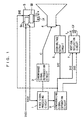
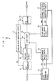
- FIG. 1 is a block diagram showing the structure of a television receiver according to the first embodiment of the present invention.
- the television receiver shown in Fig. 1 includes a video signal processing circuit 1, a chrominance signal reproduction circuit 1, a synchronizing signal separation circuit 3, a cathode ray tube (CRT) 4, a horizontal deflection circuit 5, a high-voltage output circuit 6 and a vertical deflection circuit 7.
- a horizontal deflection yoke LH and a vertical deflection yoke LV are mounted on the cathode ray tube 4.
- the video signal processing circuit 1 separates a luminance signal and a color difference signal from a video signal TVS2 supplied from the horizontal deflection circuit 5 described later and outputs the signals while supplying the video signal TVS2 to the synchronizing signal separation circuit 3.
- the chrominance signal reproduction circuit 2 reproduces a chrominance signal from the luminance signal and the color difference signal output from the video signal processing circuit 1 and supplies the reproduced chrominance signal to the cathode ray tube 4 as a display signal C.
- the synchronizing signal separation circuit 3 extracts a horizontal synchronizing signal SH2 and a vertical synchronizing signal SV2 from the video signal TVS2 supplied from the video signal processing circuit 1.
- the horizontal deflection circuit 5 includes a video signal conversion part 5A converting an input video signal TVS1 to the video signal TVS2 and an output part 5B supplying a sawtooth horizontal deflection current I H to the horizontal deflection yoke LH in synchronization with the horizontal synchronizing signal SH2 output from the synchronizing signal separation circuit 3.
- the structures and operations of the video signal conversion part 5A and the output part 5B are described later.
- the high-voltage output circuit 6 includes a high-voltage drive circuit, a flyback transformer, a dynamic auto focus control circuit and a dynamic auto focus output circuit and outputs a high voltage to the cathode ray tube 4 for focus control or the like.
- the vertical deflection circuit 7 including a vertical output circuit, supplies a sawtooth vertical deflection current I v to the vertical deflection yoke LV for vertically deflecting an electron beam in the cathode ray tube 4 in synchronization with the horizontal synchronizing signal SH2 and the vertical synchronizing signal SV2 output from the synchronizing signal separation circuit 3.
- the video signal conversion part 5A corresponds to the input means and the video signal conversion means or the input circuit and the video signal conversion circuit
- the output part 5B corresponds to the horizontal deflection current supply means or the horizontal current supply circuit
- the horizontal deflection yoke LH corresponds to the horizontal deflection coil.
- the video signal processing circuit 1, the chrominance signal reproduction circuit 2 and the synchronizing signal separation circuit 3 form the video signal processing means or the video signal processing circuit
- the vertical deflection circuit 7 corresponds to the vertical deflection current supply means or the vertical deflection current supply circuit
- the vertical deflection yoke LV corresponds to the vertical deflection coil.
- a synchronizing signal separation circuit 15 corresponds to the first synchronizing signal generation means or the first synchronizing signal generation circuit
- an expanded horizontal synchronizing pulse generation circuit 17 corresponds to the second synchronizing signal generation means or the second synchronizing signal generation circuit
- a video memory write control circuit 16 corresponds to the write control means or the write control circuit
- a video memory read control circuit 18 corresponds to the read control means or the read control circuit.
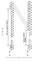
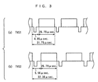
- Figs. 2(a) and 2(b) are waveform diagrams for illustrating conversion of the video signals TVS1 and TVS2 in the video signal conversion part 5A shown in Fig. 1, and Figs. 3(a) and 3(b) illustrate parts of the video signals TVS1 and TVS2 shown in Figs. 2(a) and 2(b) in an enlarged manner.
- Figs. 2(a) and 2(b) show waveforms in vertical blanking intervals of the video signals TVS1 and TVS2 and around the same respectively.
- the video signal TVS1 is an NTSC video signal.
- a vertical scanning interval has 525 horizontal scanning lines and 480 effective scanning lines and the vertical scanning frequency is 60 Hz, for example, as shown in Fig. 2(a).
- a vertical blanking interval has 45 horizontal scanning lines.
- effective scanning lines stands for horizontal scanning lines forming an effective picture area (corresponding to an interval other than the vertical blanking interval) within the vertical scanning interval.
- the video signal conversion part 5A of the horizontal deflection circuit 5 converts the video signal TVS1 to the video signal TVS2.
- a vertical scanning interval has 515 horizontal scanning lines and 480 effective scanning lines and the vertical scanning frequency is 60 Hz, for example, as shown in Fig. 2(b).
- the vertical blanking interval of the video signal TVS2 has 35 horizontal scanning lines.
- the number of horizontal scanning lines in the vertical blanking interval of the video signal TVS2 is smaller by 10 than that in the vertical blanking interval of the video signal TVS1.
- the video signal TVS1 has a horizontal blanking interval (no signal interval) of about 4.95 ⁇ sec., a video signal interval (horizontal scanning interval) of about 26.79 ⁇ sec. and a horizontal scanning line period, formed by the horizontal blanking interval and the video signal interval, of about 31.75 ⁇ sec.
- the horizontal scanning frequency of the video signal TVS1 is 31.5 kHz.
- the video signal TVS2 has a horizontal blanking interval of about 5.56 ⁇ sec., a video signal interval of about 26.79 ⁇ sec. and a horizontal scanning line period of about 32.36 ⁇ sec.
- the horizontal blanking interval of the video signal TVS2 is extended by about 0.61 ⁇ sec. as compared with the horizontal blanking interval of the video signal TVS1.
- the horizontal scanning line period of the video signal TVS2 is longer by about 0.61 ⁇ sec. than the horizontal scanning line period o the video signal TVS1.
- a prescribed number of, e.g., 10 horizontal scanning lines are deleted from the vertical blanking interval of the video signal TVS1 and the time corresponding to the deleted horizontal scanning lines is assigned to horizontal blanking intervals of the remaining horizontal scanning lines thereby extending the horizontal blanking interval of each horizontal scanning line.
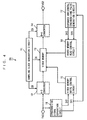
- Fig. 4 is a block diagram showing the structure of the video signal conversion part 5A.
- the video signal conversion part 5A includes a sampling clock generation circuit 11, an analog-to-digital (A-D) converter 12, a video memory 13, a digital-to-analog (D-A) converter 14, the synchronizing signal separation circuit 15, the video memory write control circuit 16, the expanded horizontal synchronizing pulse generation circuit 17 and the video memory read control circuit 18.
- A-D analog-to-digital
- D-A digital-to-analog
- the sampling clock generation circuit 11 generates a sampling clock CK of a prescribed frequency.
- the A-D converter 12 performs sampling in response to the sampling clock CK output from the sampling clock generation circuit 11, for converting the video signal TVS1 to a digital signal.
- the video memory 13 stores the digital signal output from the A-D converter 12 in response to the sampling clock CK.
- the D-A converter 14 converts the digital signal read from the video memory 13 to an analog signal in response to the sampling clock CK and outputs the analog signal as the video signal TVS2.
- the synchronizing signal separation circuit 15 extracts a horizontal synchronizing signal SH1 and a vertical synchronizing signal SV1 from the video signal TVS1.
- the video memory write control circuit 16 writes the digital signal output from the A-D converter 12 in the video memory 13 on the basis of the horizontal synchronizing signal SH1 and the vertical synchronizing signal SV1 output from the synchronizing signal separation circuit 15.
- the expanded horizontal synchronizing pulse generation circuit 17 outputs a horizontal synchronizing signal SH3 having a lower frequency than the horizontal synchronizing signal SH1 while outputting the vertical synchronizing signal SV1 on the basis of the vertical synchronizing signal SV1 output from the synchronizing signal separation circuit 15.
- the frequency of the horizontal synchronizing signal SH1 is 31.5 kHz, for example, and the frequency of the horizontal synchronizing signal SH3 is 30.9 kHz, for example.
- the video memory read control circuit 18 supplies an address signal to the video memory 13 to start reading the digital signal of a single vertical scanning interval from the video memory 13 in response to the vertical synchronizing signal SV1 output from the expanded horizontal synchronizing pulse generation circuit 17, read digital signal components corresponding to 35 horizontal scanning lines, for example, in the vertical blanking interval, thereafter skip digital signal components corresponding to a prescribed number of, e.g., 10 horizontal scanning lines, and read a digital signal component corresponding to the 46 th horizontal scanning line following the digital signal component corresponding to the 35 th horizontal scanning line.
- the single vertical scanning interval of the digital signal read from the video memory 13 has 515 horizontal scanning lines.
- the video memory read control circuit 18 decides read timing per horizontal scanning on the basis of the horizontal synchronizing signal SH3 output from the expanded horizontal synchronizing pulse generation circuit 17.
- the video memory read control circuit 18 delays read start timing of the video memory 13 in the horizontal blanking interval (silence interval) by a prescribed time.
- This delay time corresponding to the difference between the cycles of the horizontal synchronizing signals SH1 an SH3, is about 0.61 ⁇ sec. in the examples shown in Figs. 2(a) and 2(b).
- the horizontal blanking interval is extended to about 5.56 ⁇ sec., and the digital signal corresponding to each horizontal scanning line is read in synchronization with the horizontal synchronizing signal SH3.
- the total of the horizontal scanning line periods of the deleted 10 horizontal scanning lines and the total of the extended times of the horizontal blanking intervals of the remaining 515 horizontal scanning lines coincide with each other, and hence the vertical scanning frequencies of the video signals TVS1 and TVS2 are equally 60 Hz.
- the A-D converter 12 corresponds to the input means and the analog-to-digital conversion means
- the video memory 13, the D-A converter 14, the synchronizing signal separation circuit 15, the video memory write control circuit 16, the expanded horizontal synchronizing pulse generation circuit 17 and the video memory read control circuit 18 form the video signal conversion means.
- the video memory 13 corresponds to the storage means
- the video memory write control circuit 16, the expanded horizontal synchronizing pulse generation circuit 17 and the video memory read control circuit 18 form the control means
- the D-A converter 14 corresponds to the digital-to-analog conversion means.
- Fig. 5 is a block diagram showing the structure of the output part 5B.
- Figs. 6(a) to 6(c) are waveform diagrams for illustrating operations of the output part 5B.
- the output part 5B includes a horizontal AFC (automatic frequency control) circuit 20, a horizontal oscillation circuit 21, a horizontal drive circuit 22, a horizontal output transistor 23, a power supply terminal 24, a choke coil 25, a damper diode 26, a resonance capacitor 27 and a sigmoid correction capacitor 28.
- AFC automatic frequency control
- the horizontal AFC circuit 20 prevents the horizontal synchronizing signal SH2 output from the synchronizing signal separation circuit 3 shown in Fig. 1 from disturbance of horizontal synchronization caused by contamination with noise. Thus, the horizontal AFC circuit 20 improves stability of the oscillation frequency of the horizontal oscillation circuit 21 described later.
- the horizontal oscillation circuit 21 generates a pulse signal in synchronization with the horizontal synchronizing signal SH2 supplied through the horizontal AFC circuit 20.
- the horizontal drive circuit 22 amplifies and waveform-shapes the pulse signal output from the horizontal oscillation circuit 21 and supplies this pulse signal to the base of the horizontal output transistor 23.
- the horizontal output transistor 23 performs switching in response to the pulse signal supplied from the horizontal drive circuit 22.
- the emitter of the horizontal output transistor 23 is grounded.
- the collector of the horizontal output transistor 23 is connected to the power supply terminal 24 through the choke coil 25.
- the power supply terminal 24 is supplied with a power supply voltage V cc .
- the damper diode 26 has a cathode connected to the collector of the horizontal output transistor 23 and a grounded anode.
- the resonance capacitor 27 is connected in parallel with the damper diode 26.
- a series circuit of the horizontal deflection yoke LH and the sigmoid correction capacitor 28 is connected between the collector of the horizontal output transistor 23 and a ground terminal.
- the horizontal output transistor 23 corresponds to the horizontal deflection current supply means or the horizontal deflection current supply circuit.
- Fig. 6(a) shows the video signal TVS2
- Fig. 6(b) shows the horizontal deflection current I H flowing in the horizontal deflection yoke LH
- Fig. 6(c) shows a horizontal deflection pulse voltage V c generated on the collector of the horizontal output transistor 23.
- the horizontal AFC circuit 20, the horizontal oscillation circuit 21 and the horizontal drive circuit 22 apply the pulse voltage V B to the base of the horizontal output transistor 23, which in turn performs switching.
- the sawtooth horizontal deflection current I H shown in Fig. 6(b) flows in the horizontal deflection yoke LH due to the switching operation of the horizontal output transistor 23 and actions of the damper diode 26 and the resonance capacitor 27.
- the horizontal deflection sensitivity w and the horizontal scanning interval t s in the above equation (1) are constant if the deflection yoke system and the scanning system are left intact. Therefore, it is understood possible to reduce the peak value i p of the horizontal deflection current I H by increasing the power supply voltage V cc .
- the power supply voltage V cc must be increased in order to reduce the peak value V p of the horizontal deflection pulse voltage V c under such restriction that the peak value V p of the horizontal deflection pulse voltage V c is not in excess of the standard withstand voltage across the collector and the emitter of the horizontal output transistor 23.
- the ratio t s /t r of the horizontal scanning interval t s to the horizontal blanking interval t r may be reduced as understood from the above equation (2).
- the horizontal blanking interval t r of the video signal TVS2 is extended by about 0.61 ⁇ sec. as compared with the horizontal blanking interval t r of the video signal TVS1 thereby reducing the aforementioned ratio t s /t r .
- V cc V p / ⁇ ( ⁇ /2) ⁇ (t s /t r ) + 1 ⁇
- the peak value i p of the horizontal deflection current I H can be reduced from 11.20 A pp to 10.10 A pp without increasing the withstand voltage across the collector and the emitter of the horizontal output transistor 23 by increasing the pulse width (horizontal blanking interval) of the horizontal deflection pulse voltage V c .
- power consumed by the horizontal deflection circuit 5 can be reduced.
- the video memory 13, the D-A converter 14, the synchronizing signal separation circuit 15, the video memory write control circuit 16, the expanded horizontal synchronizing pulse generation circuit 17 and the video memory read control circuit 18 extend the horizontal blanking interval, whereby the pulse width of the horizontal deflection pulse voltage V c generated on the collector of the horizontal output transistor 23 can be expanded in the horizontal blanking interval.
- the power supply voltage V cc of the horizontal deflection circuit 5 can be increased and the peak value i p of the horizontal deflection current I H can be reduced without increasing the peak value V p of the horizontal deflection pulse voltage V c . Therefore, power consumption of the horizontal deflection circuit 5 can be reduced without increasing the withstand voltage across the collector and the emitter of the horizontal output transistor 23 supplying the horizontal deflection current I H to the horizontal deflection yoke LH.
- FIG. 7 is a block diagram showing the structure of a video signal conversion part 5C in the television receiver according to the second embodiment of the present invention.
- Figs. 8(a) to 8(c) are waveform diagrams for illustrating conversion of video signals in the video signal conversion part 5C shown in Fig. 7.
- the television receiver according to the second embodiment is provided with the video signal conversion part 5C shown in Fig. 7 in place of the video signal conversion part 5A of the horizontal deflection circuit 5 shown in Fig. 1.
- the video signal conversion part 5C converts a video signal TVS1 to a video signal TVS4 and supplies the video signal TVS4 to the video signal processing circuit 1 shown in Fig. 1.
- the video signal conversion part 5C shown in Fig. 7 is different from the video signal conversion part 5A shown in Fig. 4 in a point that a vertical interpolation circuit 30 is provided between an A-D converter 12 and a video memory 13 and a point that a video memory read control circuit 32 is provided in place of the video memory read control circuit 18.
- the structures of the remaining parts of the video signal conversion part 5C shown in Fig. 7 are similar to those of the video signal conversion part 5A shown in Fig. 4.
- the vertical interpolation circuit 30 performs vertical interpolation on a digital signal output from the A-D converter 12 in response to a sampling clock CK, thereby outputting a video signal TVS3 having a reduced number of effective scanning lines to the video memory 13.
- Figs. 8(a) to 8(c) show waveforms of vertical blanking intervals of the video signals TVS1, TVS3 and TVS4 and around the same.
- Fig. 8(b) shows the video signal TVS3, which is a digital signal in practice, in the form of an analog signal.
- a vertical scanning interval has 525 horizontal scanning lines and 480 effective scanning lines and the vertical scanning frequency is 60 Hz, for example, as shown in Fig. 8(a).
- a vertical blanking period has 45 horizontal scanning lines in the video signal TVS1.
- the video signal TVS3 output from the vertical interpolation circuit 30 having 480 effective scanning lines is compressed to a video signal having 470 effective scanning lines, for example, as shown in Fig. 8(b).
- a signal having no video information is supplied to 10 effective scanning lines.
- the video signal TVS3 apparently has 525 horizontal scanning lines.
- a vertical scanning interval has 515 horizontal scanning lines and 470 effective scanning lines and the vertical scanning frequency is 60 Hz, for example, as shown in Fig. 8(c).
- a vertical blanking interval has 45 horizontal scanning lines in the video signal TVS4.
- the number of effective scanning lines in the video signal TVS4 is smaller by 10 than that in the video signal TVS1.
- the video signal TVS1 has a horizontal blanking interval (no signal interval) of about 4.95 ⁇ sec., a video signal interval (horizontal scanning interval) of about 26.79 ⁇ sec. and a horizontal scanning line period, formed by the horizontal blanking interval and the video signal interval, of about 31.75 ⁇ sec.
- horizontal scanning frequency of the video signal TVS1 is 31.5 kHz.
- the video signal TVS4 has a horizontal blanking interval of about 5.56 ⁇ sec., a video signal interval of about 26.79 ⁇ sec. and a horizontal scanning line period of about 32.36 ⁇ sec., similarly to the video signal TVS2 shown in Fig. 3(b).
- the horizontal blanking interval of the video signal TVS4 is extended by about 0.61 ⁇ sec. as compared with the horizontal blanking interval of the video signal TVS1.
- the horizontal scanning line period of the video signal TVS4 is longer by about 0.61 ⁇ sec. than the horizontal scanning line period of the video signal TVS1.
- the number of effective horizontal scanning lines of an effective picture area is reduced by vertical interpolation and a time corresponding to the reduced number of effective scanning lines is assigned to horizontal blanking interval of the remaining horizontal scanning lines, thereby extending the horizontal blanking interval of each horizontal scanning line.
- the video memory read control circuit 32 decides read timing per horizontal scanning on the basis of a horizontal synchronizing signal SH3 output from an expanded horizontal synchronizing pulse generation circuit 17. In other words, the video memory read control circuit 32 delays read start timing of the video memory 13 in the horizontal blanking interval (no signal interval) by a prescribed time.
- the delay time corresponding to the difference between the cycle of a horizontal synchronizing SH1 and that of the horizontal synchronizing signal SH3, is about 0.61 ⁇ sec. in the examples shown in Figs. 2(a) and 2(b).
- the horizontal blanking interval is extended to about 5.56 ⁇ sec. and a digital signal corresponding to each horizontal scanning line is read in synchronization with the horizontal synchronizing signal SH3.
- the total of the horizontal scanning line periods of the deleted 10 horizontal scanning lines and the total of the extended times of the horizontal blanking intervals of the remaining 515 horizontal scanning lines coincide with each other, and hence the vertical scanning frequencies of the video signals TVS1 and TVS4 are equally 60 Hz.
- the vertical interpolation circuit 30, the video memory 13, the D-A converter 14, a synchronizing signal separation circuit 15, a video memory write control circuit 16, the expanded horizontal synchronizing pulse generation circuit 17 and the video memory read control circuit 32 form the video signal conversion means
- the vertical interpolation circuit 30 corresponds to the vertical interpolation means
- the video memory write control circuit 16, the expanded horizontal synchronizing pulse generation circuit 17 an the video memory read control circuit 32 form the control means.
- the vertical interpolation circuit 30, the video memory 13, the D-A converter 14, the synchronizing signal separation circuit 15, the video memory write control circuit 16, the expanded horizontal synchronizing pulse generation circuit 17 and the video memory read control circuit 32 extend the horizontal blanking interval, whereby the pulse width of a horizontal deflection pulse voltage V c generated on the collector of a horizontal output transistor 23 can be expanded in the horizontal blanking interval.
- a power supply voltage V cc of a horizontal deflection circuit 5 can be increased and a peak value i p of a horizontal deflection current I H can be reduced without increasing the peak value V p of the horizontal deflection pulse voltage V c . Therefore, power consumption of the horizontal deflection circuit 5 can be reduced without increasing the withstand voltage across the collector and the emitter of the horizontal output transistor 23 supplying the horizontal deflection current I H to a horizontal deflection yoke LH.
- a component signal may alternatively be converted by a plurality of video signal conversion parts, for example.
- the video memory 13 stores a horizontal synchronizing signal and a vertical synchronizing signal along with a video information in each of the first and second embodiments
- the video memory 13 may alternatively store only video information so that the horizontal synchronizing signal and the vertical synchronizing signal are generated in a free run and the video information stored in the video memory 13 is composited with the horizontal and vertical synchronizing signals later.
Landscapes
- Engineering & Computer Science (AREA)
- Multimedia (AREA)
- Signal Processing (AREA)
- Details Of Television Scanning (AREA)
- Television Systems (AREA)
Abstract
Description
Claims (20)
- A horizontal deflection circuit comprising:input means for inputting a video signal;video signal conversion means for deleting a prescribed number of horizontal scanning lines from a vertical blanking interval in said video signal input by said input means and assigning a time corresponding to the deleted horizontal scanning lines to horizontal blanking intervals of the remaining horizontal scanning lines thereby extending the horizontal blanking interval of each horizontal scanning line; andhorizontal deflection current supply means for supplying a horizontal deflection current to a horizontal deflection coil for retracing an electron beam in each horizontal blanking interval extended by said video signal conversion means.
- The horizontal deflection circuit according to claim 1, whereinsaid input means includes analog-to-digital conversion means for performing analog-to-digital conversion on said video signal and outputting a digital signal, andsaid video signal conversion means includes:storage means for storing said digital signal output from said analog-to-digital conversion means,control means for controlling writing and reading of said digital signal in and from said storage means thereby deleting said prescribed number of horizontal scanning lines from said vertical blanking interval and extending the horizontal blanking interval of each horizontal scanning line, anddigital-to-analog conversion means for performing digital-to-analog conversion on said digital signal read from said storage means and outputting an analog signal.
- The horizontal deflection circuit according to claim 2, wherein
said control means includes:first synchronizing signal generation means for generating a vertical synchronizing signal and a first horizontal synchronizing signal,second synchronizing signal generation means for generating a second horizontal synchronizing signal having a lower frequency than said first horizontal synchronizing signal in response to said first horizontal synchronizing signal generated by said first synchronizing signal generation means,write control means for writing said digital signal output from said analog-to-digital conversion means in said storage means in response to said first horizontal synchronizing signal and said vertical synchronizing signal, andread control means for reading said digital signal from said storage means while skipping digital signal components of said prescribed number of horizontal scanning lines in said vertical blanking interval in response to said second horizontal synchronizing signal and said vertical synchronizing signal. - A horizontal deflection circuit comprising:input means for inputting a video signal;video signal conversion means for reducing the number of horizontal scanning lines in an effective picture area of a vertical scanning interval by vertical interpolation in said video signal input by said input means and assigning a time corresponding to the reduced number of horizontal scanning lines to horizontal blanking intervals of the remaining horizontal scanning lines thereby extending the horizontal blanking interval of each horizontal scanning line; andhorizontal deflection current supply means for supplying a horizontal deflection current to a horizontal deflection coil for retracing an electron beam in each horizontal blanking interval extended by said video signal conversion means.
- The horizontal deflection circuit according to claim 4, whereinsaid input means includes analog-to-digital conversion means for performing analog-to-digital conversion on said video signal and outputting a digital signal, andsaid video signal conversion means includes:vertical interpolation means for performing vertical interpolation on said digital signal output from said analog-to-digital conversion means thereby reducing the number of horizontal scanning lines in said effective picture area of said vertical scanning interval,storage means for storing said digital signal output from said vertical interpolation means,control means for controlling writing and reading of said digital signal in and from said storage means thereby extending the horizontal blanking period of each horizontal scanning line, anddigital-to-analog conversion means for performing digital-to-analog conversion on said digital signal read from said storage means and outputting an analog signal.
- The horizontal deflection circuit according to claim 5, wherein
said control means includes:first synchronizing signal generation means for generating a vertical synchronizing signal and a first horizontal synchronizing signal,second synchronizing signal generation means for generating a second horizontal synchronizing signal having a lower frequency than said first horizontal synchronizing signal in response to said first horizontal synchronizing signal generated by said first synchronizing signal generation means,write control means for writing said digital signal output from said analog-to-digital conversion means in said storage means in response to said first horizontal synchronizing signal and said vertical synchronizing signal, andread control means for reading said digital signal from said storage means in response to said second horizontal synchronizing signal and said vertical synchronizing signal. - A horizontal deflection circuit comprising:an input circuit inputting a video signal;a video signal conversion circuit deleting a prescribed number of horizontal scanning lines from a vertical blanking interval in said video signal input by said input circuit and assigning a time corresponding to the deleted horizontal scanning lines to horizontal blanking intervals of the remaining horizontal scanning lines thereby extending the horizontal blanking interval of each horizontal scanning line; anda horizontal deflection current supply circuit supplying a horizontal deflection current to a horizontal deflection coil for retracing an electron beam in each horizontal blanking interval extended by said video signal conversion circuit.
- The horizontal deflection circuit according to claim 7, whereinsaid input circuit includes an analog-to-digital converter performing analog-to-digital conversion on said video signal and outputting a digital signal, andsaid video signal conversion circuit includes:a memory storing said digital signal output from said analog-to-digital converter,a control circuit controlling writing and reading of said digital signal in and from said memory thereby deleting said prescribed number of horizontal scanning lines from said vertical blanking interval and extending the horizontal blanking interval of each horizontal scanning line, anda digital-to-analog converter performing digital-to-analog conversion on said digital signal read from said memory and outputting an analog signal.
- The horizontal deflection circuit according to claim 8, wherein
said control circuit includes:a first synchronizing signal generation circuit generating a vertical synchronizing signal and a first horizontal synchronizing signal,a second synchronizing signal generation circuit generating a second horizontal synchronizing signal having a lower frequency than said first horizontal synchronizing signal in response to said first horizontal synchronizing signal generated by said first synchronizing signal generation circuit,a write control circuit writing said digital signal output from said analog-to-digital converter in said memory in response to said first horizontal synchronizing signal and said vertical synchronizing signal, anda read control circuit reading said digital signal from said memory while skipping digital signal components of said prescribed number of horizontal scanning lines in said vertical blanking interval in response to said second horizontal synchronizing signal and said vertical synchronizing signal. - A horizontal deflection circuit comprising:an input circuit inputting a video signal;a video signal conversion circuit reducing the number of horizontal scanning lines in an effective picture area of a vertical scanning interval by vertical interpolation in said video signal input by said input circuit and assigning a time corresponding to the reduced number of horizontal scanning lines to horizontal blanking intervals of the remaining horizontal scanning lines thereby extending the horizontal blanking interval of each horizontal scanning line; anda horizontal deflection current supply circuit supplying a horizontal deflection current to a horizontal deflection coil for retracing an electron beam in each horizontal blanking interval extended by said video signal conversion circuit.
- The horizontal deflection circuit according to claim 10, whereinsaid input circuit includes an analog-to-digital converter performing analog-to-digital conversion on said video signal and outputting a digital signal, andsaid video signal conversion circuit includes:a vertical interpolation circuit performing vertical interpolation on said digital signal output from said analog-to-digital converter thereby reducing the number of horizontal scanning lines in said effective picture area of said vertical scanning interval,a memory storing said digital signal output from said vertical interpolation circuit,a control circuit controlling writing and reading of said digital signal in and from said memory thereby extending the horizontal blanking interval of each horizontal scanning line, anda digital-to-analog converter performing digital-to-analog conversion on said digital signal read from said memory and outputting an analog signal.
- The horizontal deflection circuit according to claim 11, wherein
said control circuit includes:a first synchronizing signal generation circuit generating a vertical synchronizing signal and a first horizontal synchronizing signal,a second synchronizing signal generation circuit generating a second horizontal synchronizing signal having a lower frequency than said first horizontal synchronizing signal in response to said first horizontal synchronizing signal generated by said first synchronizing signal generation circuit,a write control circuit writing said digital signal output from said analog-to-digital converter in said memory in response to said first horizontal synchronizing signal and said vertical synchronizing signal, anda read control circuit reading said digital signal from said memory in response to said second horizontal synchronizing signal and said vertical synchronizing signal. - A television receiver comprising:input means for inputting a video signal;video signal conversion means for deleting a prescribed number of horizontal scanning lines from a vertical blanking interval in said video signal input by said input means and assigning a time corresponding to the deleted horizontal scanning lines to horizontal blanking intervals of the remaining horizontal scanning lines thereby extending the horizontal blanking interval of each horizontal scanning line;video signal processing means for extracting video information, a horizontal synchronizing signal and a vertical synchronizing signal from said video signal output by said video signal conversion means;a cathode ray tube having a horizontal deflection coil and a vertical deflection coil for scanning an electron beam with said horizontal deflection coil and said vertical deflection coil and displaying an image in response to said video information output from said video signal processing means;horizontal deflection current supply means for supplying a horizontal deflection current to said horizontal deflection coil of said cathode ray tube in synchronization with said horizontal synchronizing signal output from said video signal processing means; andvertical deflection current supply means for supplying a vertical deflection current to said vertical deflection coil of said cathode ray tube in synchronization with said horizontal synchronizing signal and said vertical synchronizing signal output from said video signal processing means.
- The television receiver according to claim 13, whereinsaid input means includes analog-to-digital conversion means for performing analog-to-digital conversion on said video signal and outputting a digital signal, andsaid video signal conversion means includes:storage means for storing said digital signal output from said analog-to-digital conversion means,control means for controlling writing and reading of said digital signal in and from said storage means thereby deleting said prescribed number of horizontal scanning lines from said vertical blanking interval and extending the horizontal blanking interval of each horizontal scanning line, anddigital-to-analog conversion means for performing digital-to-analog conversion on said digital signal read from said storage means and outputting an analog signal.
- A television receiver comprising:input means for inputting a video signal;video signal conversion means for reducing the number of horizontal scanning lines in an effective picture area of a vertical scanning interval by vertical interpolation in said video signal input by said input means and assigning a time corresponding to the reduced number of horizontal scanning lines to horizontal blanking intervals of the remaining horizontal scanning lines thereby extending the horizontal blanking interval of each horizontal scanning line;video signal processing means for extracting video information, a horizontal synchronizing signal and a vertical synchronizing signal from said video signal output by said video signal conversion means;a cathode ray tube having a horizontal deflection coil and a vertical deflection coil for scanning an electron beam with said horizontal deflection coil and said vertical deflection coil and displaying an image in response to said video information output from said video signal processing means;horizontal deflection current supply means for supplying a horizontal deflection current to said horizontal deflection coil of said cathode ray tube in synchronization with said horizontal synchronizing signal output from said video signal processing means; andvertical deflection current supply means for supplying a vertical deflection current to said vertical deflection coil of said cathode ray tube in synchronization with said horizontal synchronizing signal and said vertical synchronizing signal output from said video signal processing means.
- The television receiver according to claim 15, whereinsaid input means includes analog-to-digital conversion means for performing analog-to-digital conversion on said video signal and outputting a digital signal, andsaid video signal conversion means includes:vertical interpolation means for performing vertical interpolation on said digital signal output from said analog-to-digital conversion means thereby reducing the number of horizontal scanning lines in said effective picture area of said vertical scanning interval,storage means for storing said digital signal output from said vertical interpolation means,control means for controlling writing and reading of said digital signal in and from said storage means thereby extending the horizontal blanking interval of each horizontal scanning line, anddigital-to-analog conversion means for performing digital-to-analog conversion on said digital signal read from said storage means and outputting an analog signal.
- A television receiver comprising:an input circuit inputting a video signal;a video signal conversion circuit deleting a prescribed number of horizontal scanning lines from a vertical blanking interval in said video signal input by said input circuit and assigning a time corresponding to the deleted horizontal scanning lines to horizontal blanking intervals of the remaining horizontal scanning lines thereby extending the horizontal blanking interval of each horizontal scanning line;a video signal processing circuit extracting video information, a horizontal synchronizing signal and a vertical synchronizing signal from said video signal output by said video signal conversion circuit;a cathode ray tube having a horizontal deflection coil and a vertical deflection coil for scanning an electron beam with said horizontal deflection coil and said vertical deflection coil and displaying an image in response to said video information output from said video signal processing circuit;a horizontal deflection current supply circuit supplying a horizontal deflection current to said horizontal deflection coil of said cathode ray tube in synchronization with said horizontal synchronizing signal output from said video signal processing circuit; anda vertical deflection current supply circuit supplying a vertical deflection current to said vertical deflection coil of said cathode ray tube in synchronization with said horizontal synchronizing signal and said vertical synchronizing signal output from said video signal processing circuit.
- The television receiver according to claim 17, whereinsaid input circuit includes an analog-to-digital converter performing analog-to-digital conversion on said video signal and outputting a digital signal, andsaid video signal conversion circuit includes:a memory storing said digital signal output from said analog-to-digital converter,a control circuit controlling writing and reading of said digital signal in and from said memory thereby deleting said prescribed number of horizontal scanning lines from said vertical blanking interval and extending the horizontal blanking interval of each horizontal scanning line, anda digital-to-analog converter performing digital-to-analog conversion on said digital signal read from said memory and outputting an analog signal.
- A television receiver comprising:an input circuit inputting a video signal;a video signal conversion circuit reducing the number of horizontal scanning lines in an effective picture area of a vertical scanning interval by vertical interpolation in said video signal input by said input circuit and assigning a time corresponding to the reduced number of horizontal scanning lines to horizontal blanking intervals of the remaining horizontal scanning lines thereby extending the horizontal blanking interval of each horizontal scanning line;a video signal processing circuit extracting video information, a horizontal synchronizing signal and a vertical synchronizing signal from said video signal output by said video signal conversion circuit;a cathode ray tube having a horizontal deflection coil and a vertical deflection coil for scanning an electron beam with said horizontal deflection coil and said vertical deflection coil and displaying an image in response to said video information output from said video signal processing circuit;a horizontal deflection current supply circuit supplying a horizontal deflection current to said horizontal deflection coil of said cathode ray tube in synchronization with said horizontal synchronizing signal output from said video signal processing circuit; anda vertical deflection current supply circuit supplying a vertical deflection current to said vertical deflection coil of said cathode ray tube in synchronization with said horizontal synchronizing signal and said vertical synchronizing signal output from said video signal processing circuit.
- The television receiver according to claim 19, whereinsaid input circuit includes an analog-to-digital converter performing analog-to-digital conversion on said video signal and outputting a digital signal, andsaid video signal conversion circuit includes:a vertical interpolation circuit performing vertical interpolation on said digital signal output from said analog-to-digital converter thereby reducing the number of horizontal scanning lines in said effective picture area of said vertical scanning interval,a memory storing said digital signal output from said vertical interpolation circuit,a control circuit controlling writing and reading of said digital signal in and from said memory thereby extending the horizontal blanking interval of each horizontal scanning line, anda digital-to-analog converter performing digital-to-analog conversion on said digital signal read from said memory and outputting an analog signal.
Applications Claiming Priority (2)
| Application Number | Priority Date | Filing Date | Title |
|---|---|---|---|
| JP2000151020A JP2001333392A (en) | 2000-05-23 | 2000-05-23 | Horizontal deflection circuit and television receiver |
| JP2000151020 | 2000-05-23 |
Publications (2)
| Publication Number | Publication Date |
|---|---|
| EP1158781A2 true EP1158781A2 (en) | 2001-11-28 |
| EP1158781A3 EP1158781A3 (en) | 2003-07-23 |
Family
ID=18656642
Family Applications (1)
| Application Number | Title | Priority Date | Filing Date |
|---|---|---|---|
| EP01304488A Withdrawn EP1158781A3 (en) | 2000-05-23 | 2001-05-22 | Horizontal deflection circuit and television receiver |
Country Status (6)
| Country | Link |
|---|---|
| US (1) | US6704056B2 (en) |
| EP (1) | EP1158781A3 (en) |
| JP (1) | JP2001333392A (en) |
| KR (1) | KR100708513B1 (en) |
| CN (1) | CN1225108C (en) |
| MY (1) | MY127221A (en) |
Cited By (1)
| Publication number | Priority date | Publication date | Assignee | Title |
|---|---|---|---|---|
| WO2003107654A1 (en) * | 2002-06-18 | 2003-12-24 | Koninklijke Philips Electronics N.V. | Control circuit and method for controlling an electrical signal over a load such as a deflection circuit of a cathode ray tube |
Families Citing this family (9)
| Publication number | Priority date | Publication date | Assignee | Title |
|---|---|---|---|---|
| KR100393060B1 (en) * | 2000-12-22 | 2003-07-31 | 삼성전자주식회사 | Apparatus for controlling a supply voltage of convergence amplifier and convergence correcting apparatus therefor |
| JP3719974B2 (en) * | 2001-11-26 | 2005-11-24 | 株式会社アドバンスト・ディスプレイ | Liquid crystal drive device |
| TW561783B (en) * | 2002-03-12 | 2003-11-11 | Via Tech Inc | Image processing method and device |
| TW527824B (en) * | 2002-03-12 | 2003-04-11 | Via Tech Inc | Adative-deflicker processing method and adaptive deflicker filter |
| TW563353B (en) * | 2002-03-12 | 2003-11-21 | Via Tech Inc | Clock signal synthesizer with multiple frequency outputs and method for synthesizing clock signal |
| KR100568179B1 (en) * | 2003-09-22 | 2006-04-05 | 삼성전자주식회사 | Display system and its synchronization signal conversion method |
| JP2006174363A (en) * | 2004-12-20 | 2006-06-29 | Nec Electronics Corp | Frame synchronizer, optical disk drive, information recording/reproducing device, and signal synchronizing method |
| US20100269137A1 (en) * | 2006-11-07 | 2010-10-21 | Sony Corporation | Transmission device, video signal transmission method for transmission device, reception device, and video signal reception method for reception device |
| CN102811334A (en) * | 2012-07-10 | 2012-12-05 | 杭州海康威视数字技术股份有限公司 | System and method for transmitting high-definition video signal in dome camera |
Family Cites Families (13)
| Publication number | Priority date | Publication date | Assignee | Title |
|---|---|---|---|---|
| US4760455A (en) * | 1985-11-29 | 1988-07-26 | Canon Kabushiki Kaisha | Picture output device |
| JP3231142B2 (en) * | 1993-06-18 | 2001-11-19 | 株式会社日立製作所 | Video compression / expansion circuit and device |
| US5550442A (en) * | 1993-12-16 | 1996-08-27 | Matsushita Electric Industrial Co., Ltd. | Horizontal deflection circuit |
| US5812210A (en) * | 1994-02-01 | 1998-09-22 | Hitachi, Ltd. | Display apparatus |
| KR960036638A (en) * | 1995-03-31 | 1996-10-28 | 김광호 | Vertical stretching apparatus and method of image in TV apparatus |
| JPH09284671A (en) * | 1996-04-18 | 1997-10-31 | Toshiba Corp | Scan line converter |
| JPH09322011A (en) | 1996-05-30 | 1997-12-12 | Matsushita Electric Ind Co Ltd | Television receiver |
| KR100225072B1 (en) * | 1996-12-18 | 1999-10-15 | 윤종용 | Format Converter |
| KR19980075337A (en) * | 1997-03-31 | 1998-11-16 | 배순훈 | TV's horizontal deflection screen variable control device |
| JPH10319932A (en) * | 1997-05-16 | 1998-12-04 | Sony Corp | Display device |
| JPH11234591A (en) | 1998-02-10 | 1999-08-27 | Hitachi Ltd | Television receiver |
| US6262779B1 (en) | 1998-02-10 | 2001-07-17 | Hitachi, Ltd | Display apparatus with circuit expanding horizontal retrace interval of horizontal deflection current |
| JP2002010098A (en) * | 2000-06-27 | 2002-01-11 | Matsushita Electric Ind Co Ltd | Horizontal deflection circuit and bidirectional horizontal deflection device |
-
2000
- 2000-05-23 JP JP2000151020A patent/JP2001333392A/en active Pending
-
2001
- 2001-05-22 EP EP01304488A patent/EP1158781A3/en not_active Withdrawn
- 2001-05-22 KR KR1020010028016A patent/KR100708513B1/en not_active Expired - Fee Related
- 2001-05-22 MY MYPI20012415 patent/MY127221A/en unknown
- 2001-05-22 US US09/861,587 patent/US6704056B2/en not_active Expired - Fee Related
- 2001-05-23 CN CNB011197552A patent/CN1225108C/en not_active Expired - Fee Related
Cited By (1)
| Publication number | Priority date | Publication date | Assignee | Title |
|---|---|---|---|---|
| WO2003107654A1 (en) * | 2002-06-18 | 2003-12-24 | Koninklijke Philips Electronics N.V. | Control circuit and method for controlling an electrical signal over a load such as a deflection circuit of a cathode ray tube |
Also Published As
| Publication number | Publication date |
|---|---|
| CN1336758A (en) | 2002-02-20 |
| KR20010107639A (en) | 2001-12-07 |
| CN1225108C (en) | 2005-10-26 |
| US6704056B2 (en) | 2004-03-09 |
| US20010048480A1 (en) | 2001-12-06 |
| MY127221A (en) | 2006-11-30 |
| JP2001333392A (en) | 2001-11-30 |
| EP1158781A3 (en) | 2003-07-23 |
| KR100708513B1 (en) | 2007-04-16 |
Similar Documents
| Publication | Publication Date | Title |
|---|---|---|
| US6704056B2 (en) | Horizontal deflection circuit and television receiver | |
| US6262779B1 (en) | Display apparatus with circuit expanding horizontal retrace interval of horizontal deflection current | |
| US6529245B2 (en) | Display device also compatible with digital broadcasts | |
| US6525778B1 (en) | Image display unit for displaying undistorted images having different aspect ratios | |
| US6011593A (en) | Cathode ray tube with apparatus for reducing variation of deflection size due to brightness changes | |
| US5519445A (en) | Television receiver having caption displaying capability | |
| US6297861B1 (en) | Images adjusting circuit of display monitor | |
| US5043638A (en) | Dynamic focus adjusting voltage generating circuit | |
| EP0865198B1 (en) | Method and device for arranging digitized image signals or data in orthogonal rows and columns | |
| JP2001333393A (en) | Horizontal deflection circuit and television receiver | |
| US6529176B1 (en) | Image display and horizontal speed modulator | |
| JP2000022981A (en) | Display device | |
| JP2004304654A (en) | Video signal processing circuit and video display device having the same | |
| KR100284958B1 (en) | Line flicker suppression by adaptive interlacing release | |
| JP2747137B2 (en) | Television receiver | |
| JP2000293126A (en) | Display device | |
| US20050117058A1 (en) | Video display unit | |
| KR0132511B1 (en) | Color Video Printer using FOCRT | |
| JPH0523014Y2 (en) | ||
| JP2737544B2 (en) | High voltage generation circuit | |
| JPH07107324A (en) | Video display device and television receiver including the same | |
| JP2000022982A (en) | Display device | |
| JPH03155283A (en) | Horizontal deflection circuit | |
| JP2002320103A (en) | Horizontal deflection circuit | |
| JPH11234591A (en) | Television receiver |
Legal Events
| Date | Code | Title | Description |
|---|---|---|---|
| PUAI | Public reference made under article 153(3) epc to a published international application that has entered the european phase |
Free format text: ORIGINAL CODE: 0009012 |
|
| AK | Designated contracting states |
Kind code of ref document: A2 Designated state(s): AT BE CH CY DE DK ES FI FR GB GR IE IT LI LU MC NL PT SE TR |
|
| AX | Request for extension of the european patent |
Free format text: AL;LT;LV;MK;RO;SI |
|
| PUAL | Search report despatched |
Free format text: ORIGINAL CODE: 0009013 |
|
| AK | Designated contracting states |
Designated state(s): AT BE CH CY DE DK ES FI FR GB GR IE IT LI LU MC NL PT SE TR |
|
| AX | Request for extension of the european patent |
Extension state: AL LT LV MK RO SI |
|
| 17P | Request for examination filed |
Effective date: 20030911 |
|
| AKX | Designation fees paid |
Designated state(s): DE FR GB |
|
| STAA | Information on the status of an ep patent application or granted ep patent |
Free format text: STATUS: THE APPLICATION HAS BEEN WITHDRAWN |
|
| 18W | Application withdrawn |
Effective date: 20070523 |