EP1157839A2 - Printing press and printing press control method - Google Patents
Printing press and printing press control method Download PDFInfo
- Publication number
- EP1157839A2 EP1157839A2 EP01250172A EP01250172A EP1157839A2 EP 1157839 A2 EP1157839 A2 EP 1157839A2 EP 01250172 A EP01250172 A EP 01250172A EP 01250172 A EP01250172 A EP 01250172A EP 1157839 A2 EP1157839 A2 EP 1157839A2
- Authority
- EP
- European Patent Office
- Prior art keywords
- ink
- film thickness
- thickness distribution
- ink film
- distribution formation
- Prior art date
- Legal status (The legal status is an assumption and is not a legal conclusion. Google has not performed a legal analysis and makes no representation as to the accuracy of the status listed.)
- Granted
Links
Images






Classifications
-
- B—PERFORMING OPERATIONS; TRANSPORTING
- B41—PRINTING; LINING MACHINES; TYPEWRITERS; STAMPS
- B41F—PRINTING MACHINES OR PRESSES
- B41F33/00—Indicating, counting, warning, control or safety devices
-
- B—PERFORMING OPERATIONS; TRANSPORTING
- B41—PRINTING; LINING MACHINES; TYPEWRITERS; STAMPS
- B41F—PRINTING MACHINES OR PRESSES
- B41F31/00—Inking arrangements or devices
-
- B—PERFORMING OPERATIONS; TRANSPORTING
- B41—PRINTING; LINING MACHINES; TYPEWRITERS; STAMPS
- B41P—INDEXING SCHEME RELATING TO PRINTING, LINING MACHINES, TYPEWRITERS, AND TO STAMPS
- B41P2227/00—Mounting or handling printing plates; Forming printing surfaces in situ
- B41P2227/70—Forming the printing surface directly on the form cylinder
-
- B—PERFORMING OPERATIONS; TRANSPORTING
- B41—PRINTING; LINING MACHINES; TYPEWRITERS; STAMPS
- B41P—INDEXING SCHEME RELATING TO PRINTING, LINING MACHINES, TYPEWRITERS, AND TO STAMPS
- B41P2233/00—Arrangements for the operation of printing presses
- B41P2233/10—Starting-up the machine
-
- B—PERFORMING OPERATIONS; TRANSPORTING
- B41—PRINTING; LINING MACHINES; TYPEWRITERS; STAMPS
- B41P—INDEXING SCHEME RELATING TO PRINTING, LINING MACHINES, TYPEWRITERS, AND TO STAMPS
- B41P2233/00—Arrangements for the operation of printing presses
- B41P2233/10—Starting-up the machine
- B41P2233/11—Pre-inking
Definitions
- the present invention relates to a printing press and, more particularly, to a printing press having an on-machine plate making function of exposing an image on a printing plate mounted on a plate cylinder and an ink film thickness control function.
- a printing press has been designed to directly perform plate making by using a plate making apparatus incorporated in the printing press itself. That is, a graphic pattern (image) is exposed on a printing plate (raw plate) mounted on a plate cylinder by irradiating it with a laser beam from the head of a plate making apparatus incorporated in a printing unit instead of using a plate making apparatus provided independently of the printing press. This operation is called on-machine plate making.
- the printing press is accelerated to a designated rotational speed.
- laser radiation exposure
- the head is moved in the axial direction of the plate cylinder during exposure to expose an image on the entire plate.
- the exposure time is determined by the size of the plate and the designated rotational speed during exposure.
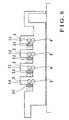
- Fig. 8 shows how plate making apparatuses are incorporated in a four-color web offset printing press.
- reference numerals 1-1 to 1-4 denote printing units for the respective ink colors.
- Plate making apparatuses 2-1 to 2-4 are respectively incorporated in the printing units 1-1 to 1-4.
- the plate making apparatuses 2-1 to 2-4 are normally located at the positions indicated by the chain double-dashed lines in Fig. 8 and brought near to plate cylinders 3 in the printing units 1-1 to 1-4 when exposure is performed.
- Reference numeral 4 denotes a blanket cylinder which is in contact opposite to the plate cylinder and on which a blanket is mounted. Impression cylinders (not shown) are respectively placed below the blanket cylinders 4.
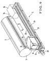
- Fig. 9 shows the main part of a plate making apparatus 2.
- the plate making apparatus 2 includes an exposure apparatus 2b having a head 2a.
- the exposure apparatus 2b is fixed on a table 2c.
- the table 2c moves in the axial direction (the direction indicated by arrows A and B in Fig. 9) of the plate cylinder 3 while being guided by rails 2f1 and 2f2 on a stage 2f.
- a raw plate 5 before plate making is mounted on the plate cylinder 3.
- Fig. 10 shows the main part of the inking device (inker) in a printing unit 1.
- Reference numeral 6 denotes an ink fountain; 7, an ink stored in the ink fountain 6; 8, an ink fountain roller; 9, a plurality of ink fountains aligned in the axial direction of the ink fountain roller 8; 10, an ink ductor roller; 11, an ink roller group; and 12, a printing plate on which an image has already been exposed.
- the ink 7 is supplied from the ink fountain 6 onto the surface of the ink fountain roller 8 through a portion between the ink fountain key 9 and the ink fountain roller 8.
- the ink supplied to the ink fountain roller 8 is supplied to the printing plate 12 via the ink roller group 11 upon ink feed operation of the ink ductor roller 10.
- the ink supplied to the printing plate 12 is printed on printing paper.
- the opening amount of the ink fountain key 9, the rotation amount of the ink fountain roller 8, and the like are preset to values corresponding to the image on the printing plate 12. More specifically, by setting the opening amount of the ink fountain key 9, the rotation amount of the ink fountain roller 8, and the like to the values corresponding to the image on the printing plate 12, the ink 7 in the ink fountain 6 is supplied to the printing plate 12 via the ink roller group 11. In this case, test printing is performed before final printing to obtain a satisfactory tone while adjusting .the amount of ink to be supplied. With this operation, a desired ink film thickness distribution (ink film thickness gradient) is formed on the ink roller group 11.
- ink removing operation is performed first. More specifically, ink removing is selected on a display (not shown) after a printing unit is selected.
- ink removing operation the ink feed operation of the ink ductor roller 10 is set in the OFF state, and the printing press is driven while the old printing plate is mounted to print out a predetermined number of sheets.
- a minimum ink film thickness distribution Ma required during printing is left on the ink roller group 11, which decreases in thickness from upstream to downstream. That is, the basic ink film thickness distribution Ma corresponding to a portion of the printing plate 12 which has no image is left.
- Pre-inking 2 is then selected on the display to perform operation of pre-inking 2.
- pre-inking 2 after the opening amount of the ink fountain key 9, the rotation amount of the ink fountain roller 8, and the like are preset to values corresponding to the image on the printing plate 12, the printing press is driven, and the ink feed operation of the ink ductor roller 10 is performed a predetermined number of times.
- an ink film thickness distribution (to be referred to as image ink film thickness distribution hereinafter) Mb corresponding to the image on the printing plate 12 is superimposed on the basic ink film thickness distribution Ma left on the ink roller group 11.
- test printing corresponding to a predetermined number of sheets is performed while the printing plate is changed to the new printing plate 12, thereby performing density checks on printing products produced by test printing. In the density checks, if a satisfactory tone is obtained, ink film thickness control by "pre-inking 2" is terminated, and final printing is started.
- the ink roller group 11 holds no ink, e.g., the printing plate 12 is mounted on the surface of the plate cylinder 3 for the first time, a printing unit is selected on the display first, and then pre-inking 1 is selected.
- pre-inking 1 the total opening amount of the ink fountain keys 9 is initialized to a reference opening amount (e.g., 50%), and the rotation amount of the ink fountain roller 8 is initialized to a reference rotation amount (e.g., 50%).
- the printing press is driven, and the ink feed operation of the ink ductor roller 10 is performed a predetermined number of times to form the basic ink film thickness distribution Ma on the ink roller group 11.
- the opening amount of the ink fountain key 9 and the rotation amount of the ink fountain roller 8 are preset to values corresponding to the image on the new printing plate 12.
- the ink feed operation of the ink ductor roller 10 is then performed a predetermined number of times to superimpose the image ink film thickness distribution Mb corresponding to the printing plate 12 on the basic ink film thickness distribution Ma formed on the ink roller group 11.
- test printing corresponding to a predetermined number of sheets is performed, and density checks are made on printing products produced by test printing. In these density checks, if a satisfactory tone is obtained, ink film thickness control by "pre-inking 1" is terminated, and final testing is started.
- FIG. 12A shows conventional steps in on-machine plate making including a preparatory process (ink removing, cleaning of the impression cylinder and blanket, paper size/paper thickness preset operation, plate change, and the like) and forming an ink film thickness distribution by pre-inking 2.
- Fig. 12B shows conventional steps in on-machine plate making without any preparatory process and forming an ink film thickness distribution by pre-inking 2.
- ink removing is performed while an old printing plate is mounted on the plate cylinder 3 (step S21) to leave the basic ink film thickness distribution Ma on the ink roller group 11.
- the impression cylinder and blanket are cleaned (step S22).
- a paper size/paper thickness is preset (step S23).
- An automatic plate change unit (not shown) is driven to change the old printing plate mounted on the plate cylinder 3 with a raw plate (step S24).
- the plate making apparatus 2 is then driven to perform exposure, thereby exposing an image on the raw plate 5 (step S25).
- Pre-inking 2 is performed (step S26) to superimpose the image ink film thickness distribution Mb corresponding to the image exposed on the raw plate 5 on the basic ink film thickness distribution Ma left on the ink roller group 11.
- test printing is performed (step S27). If a satisfactory tone is obtained, the flow advances to final printing (step S28).
- step S25 After an image is exposed on the raw plate 5 by the exposure in step S25, pre-inking 2 is performed (step S26). Test printing is then performed (step S27), and the flow advances to final printing (step S28).
- the exposure time in step S25 is determined by the size of a plate and a designated rotational speed in exposure. According to a conventional, standard plate making method, the exposure time is about 3 min and 40 sec. According to a conventional, standard ink film thickness control method, it takes about 1 min and 30 sec to form an ink film thickness distribution by pre-inking 2 in step S26.
- Figs. 13A and 13B show conventional steps in serially performing on-machine plate making and ink film thickness distribution formation by pre-inking 1.
- Fig. 13A shows conventional steps in on-machine plate making and ink film thickness distribution formation by pre-inking 2 with a preparatory process.
- Fig. 13B shows conventional steps in on-machine plate making and ink film thickness distribution formation by pre-inking 2 without any preparatory process.
- the flow starts with a preparatory process including cleaning of the impression cylinder, blanket, and inker, paper size/paper thickness presetting, and plate change. That is, the impression cylinder, blanket, and inker are cleaned (step S11). Concurrently with this cleaning operation, paper size/paper thickness presetting is performed (step S12). The old printing plate mounted on the plate cylinder 3 is changed to the raw plate 5 by using the automatic plate change unit (step S13). The plate making apparatus 2 is then driven to perform exposure so as to expose an image on the raw plate 5 (step S14). Pre-inking 1 is performed (step S15) to form the ink film thickness distributions Ma and Mb. After the formation of the ink film thickness distributions Ma and Mb, test printing is performed (step S16). If a satisfactory tone is obtained, the flow advances to final printing (step S17).
- a preparatory process including cleaning of the impression cylinder, blanket, and inker, paper size/paper thickness presetting, and plate change. That is, the impression cylinder, blanket, and inker are cleaned
- step S14 After an image is formed on the raw plate 5 by exposure in step S14, pre-inking 1 is performed (step S15). After test printing is performed (step S16), the flow advances to final printing (step S17).
- the exposure time in step S14 is determined by the size of a plate and the designated rotational speed in exposure. According to a conventional, standard plate making method, the exposure time is about 3 min and 40 sec. It takes about 2 min and 30 sec to form an ink film thickness distribution by pre-inking 1 in step S15.
- an ink film thickness distribution is formed (step S26) between exposure (step S25) and test printing (step S27).
- step S15 an ink film thickness distribution is formed (step S15) between exposure (step S14) and test printing (step S16).
- a printing press comprising an ink roller group for supplying ink stored in an ink fountain to a printing plate mounted on a plate cylinder, image exposing means for exposing an image on a printing plate before plate making which is mounted on the plate cylinder, ink film thickness distribution formation means for forming an ink film thickness distribution corresponding to the image to be exposed on the printing plate on the ink roller group, and control means for performing image exposing and ink film thickness distribution formation concurrently at least partly by controlling the image exposing means and the ink film thickness distribution formation means.
- Figs. 1A and 1B show steps in continuously executing on-machine plate making and ink film thickness distribution formation by pre-inking 2 (in combination) with and without a preparatory process.
- Fig. 1A corresponds to the steps in Fig. 12A.
- Fig. 1B corresponds to the steps in Fig. 12B.
- the arrangement of a printing press will be described with reference to Fig. 8 to 10.
- step S26 which is one of the steps in forming an ink film thickness distribution by pre-inking 2
- step S24 the step of presetting the opening amount of an ink fountain key 9 to a value corresponding to an image to be exposed on a raw plate 5
- step S26 which is one of the steps in forming an ink film thickness distribution by pre-inking 2
- the preparatory process is constituted by cleaning of the impression cylinder and blanket (step S22), paper size/paper thickness presetting (step S23), and automatic plate change (step S24).
- An operation time (designated ink fountain key opening amount setting time) tp4 taken to preset the opening amount of the ink fountain key 9 to a designated opening amount is excluded from a time (pre-inking time) tp taken to form an ink film thickness distribution by pre-inking 2, as indicated by equation (1) described later.
- an exposure time tr there is a difference between an exposure time tr and the time tp taken to form an ink film thickness distribution by pre-inking 2.
- the time tp taken to form an ink film thickness distribution by pre-inking 2 is shorter than the exposure time tr. If, therefore, exposure and ink film thickness distribution formation by pre-inking 2 are simultaneously started, the exposure is not completed even after the completion of ink film thickness distribution formation by pre-inking 2. In this case, since the printing press keeps rotating until the exposure is completed, the ink film thickness distribution changes. As a consequence, a desired ink film thickness distribution may not be obtained when the exposure is completed, and test printing may be prolonged.
- the start timing of ink film thickness distribution formation by pre-inking 2 is delayed to simultaneously terminate the exposure and ink film thickness distribution formation by pre-inking 2.
- the time tp taken to form an ink film thickness distribution by pre-inking 2 varies depending on the image area ratio of an image to be exposed on the raw plate 5.
- the exposure time tr is determined by the size of the raw plate 5 and a designated rotational speed in exposure.
- the exposure time tr and the time tp taken to form an ink film thickness distribution by pre-inking 2 are calculated.
- This wait time tw will be termed as a pre-inking wait time.
- the fountain roller portion designated ink film thickness distribution formation time tp5 is the value obtained by adding the time spent to preset the rotation amount of the ink fountain roller 8 to a value (designated rotation amount) corresponding to the image to be exposed on the raw plate 5 to the time spend to form an ink film having the thickness specified by the designated opening amount of the ink fountain key 9 preset in step S26-1 up to a portion on the ink fountain roller 8 which is in contact with an ink ductor roller 10.
- the inker portion designated ink film thickness distribution formation time tp6 is the time spent to superimpose an ink film thickness distribution (designated ink film thickness distribution) Mb corresponding to the image to be exposed on the raw plate 5 on a basic ink film thickness distribution Ma left on the ink roller group 11 by performing ink feed operation of the ink ductor roller 10 a predetermined number of times.
- step S25 exposure (step S25) in on-machine plate making is performed concurrently with ink film thickness distribution formation by pre-inking 2 (step S26), and the start timing of ink film thickness distribution formation by pre-inking 2 is delayed to simultaneously complete the two operations.
- the opening amount of the ink fountain key 9 is preset to a value corresponding to the image to be exposed on the raw plate 5 in step S26, and the fountain key designated opening amount setting time tp4 is included in the time tp taken to form an ink film thickness distribution by pre-inking 2.
- Figs. 2A and 2B show the steps in continuously executing on-machine plate making and ink film thickness distribution formation by pre-inking 1 (in combination) with and without a preparatory process.
- Fig. 2A which shows the case with the preparatory process, corresponds tc the steps in Fig. 13A.
- Fig. 2B which shows the case without any preparatory process, corresponds to the steps in Fig. 13B.
- exposure in on-machine plate making and ink film thickness distribution formation by pre-inking 1 are concurrently executed, and the start timing of ink film thickness distribution formation by pre-inking 1 is delayed to simultaneously complete the two operations.
- presetting of the opening amount of the ink fountain key 9 to a reference opening amount is performed concurrently with the preparatory process.
- the preparatory process includes cleaning of the impression cylinder, blanket, and inker (step S11), paper size/paper thickness presetting (step S12), and automatic plate change (step S13).
- An operation time (entire fountain key reference opening amount setting time) tp1 spent to preset the opening amount of the ink fountain key 9 to the reference opening amount is excluded from the time (pre-inking time) tp taken to form an ink film thickness distribution by pre-inking 1, as indicated by equation (3) to be described later.
- the exposure time tr there is a difference between the exposure time tr and the time tp taken to form an ink film thickness distribution by pre-inking 2.
- the time tp taken to form an ink film thickness distribution by pre-inking 2 is shorter than the exposure time tr. If, therefore, exposure and ink film thickness distribution formation by pre-inking 2 are simultaneously started, the exposure is not completed even after the completion of ink film thickness distribution formation by pre-inking 2. In this case, since the printing press keeps rotating until the exposure is completed, the ink film thickness distribution changes. As a consequence, a desired ink film thickness distribution may not be obtained when the exposure is completed, and test printing may be prolonged.
- the start timing of ink film thickness distribution formation by pre-inking 2 is delayed to simultaneously terminate the exposure and ink film thickness distribution formation by pre-inking 2.
- the time tp taken to form an ink film thickness distribution by pre-inking 2 varies depending on the image area ratio of an image to be exposed on the raw plate 5.
- the exposure time tr is determined by the size of the raw plate 5 and a designated rotational speed in exposure.
- the fountain roller portion basic ink film thickness distribution formation time tp2 is the value obtained by adding the time spent to preset the rotation amount of the ink fountain roller 8 to a reference rotation amount to the time spent to form an ink film having the thickness specified by the reference opening amount of the ink fountain key 9 preset in step S15-1 up to a portion on the ink fountain roller 8 which is in contact with the ink ductor roller 10.
- the inker portion basic ink film thickness distribution formation time tp3 is the time spent to form the basic ink film thickness distribution Ma on the ink roller group 11 by performing ink feed operation of the ink ductor roller 10 a predetermined number of times.
- step S14 exposure in on-machine plate making (step S14) and ink film thickness distribution formation by pre-inking 1 (step S15) are concurrently executed, and the start timing of ink film thickness distribution formation by pre-inking 1 is delayed to simultaneously complete the two operations.
- the opening amount of the ink fountain key 9 is preset to a reference opening amount in step S15, and entire fountain key reference opening amount setting time tp1 is included in the time tp taken to form an ink film thickness distribution by pre-inking 1.
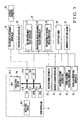
- Fig. 3 shows a printing press for performing the above continuous processing according to an embodiment of the present invention.
- reference numeral 14 denotes a main controller; 15, an on-machine plate making controller for performing plate making with respect to the raw plate 5 mounted on a plate cylinder 3 by controlling an exposure apparatus 28; 16, a printing press controller for controlling the printing operation of the printing press; 17, an ink feed mechanism ON/OFF controller (to be referred to as an ink feed controller hereinafter) for ON/OFF-controlling the ink feed operation of the ink ductor roller; 18, an ink fountain roller rotational amount controller for controlling the rotation amount of the ink fountain roller 8; 19, an ink fountain key opening degree controller for controlling the opening degree of the ink fountain key 9; 20, a floppy disk drive (to be referred to as a drive unit hereinafter) for reading out the image area ratio of the image to be exposed on the raw plate 5 from a floppy disk; 21, an automatic plate change unit for automatically change an old plate with the new plate 12; 22, an in
- the main controller 14 includes a CPU (Central Processing Unit) 14-1, ROM (Read Only Memory) 14-2, RAM (Random Access Memory) 14-3, interfaces (I/Os) 14-4 to 14-6, and touch panel display 14-7.
- the CPU 14-1 includes a calculating section 14a for calculating the time tp according to equations (1) to (4), and also calculating the respective times tp1 to tp6, tw, and tr.
- the CPU 14-1 obtains various kinds of input information supplied via the interfaces 14-4 to 14-6 and performs various operations upon accessing the RAM 14-3 in accordance with the programs stored in the ROM 14-2.
- Various kinds of processing information in the CPU 14-1 are output to the display 14-7, on-machine plate making controller 15, printing press controller 16, ink feed controller 17, ink fountain roller rotational amount controller 18, ink fountain key opening degree controller 19, drive unit 20, automatic plate change unit 21, inker cleaning controller 22, blanket cleaning controller 23, impression cylinder clearing unit 24, paper thickness presetting controller 25, and paper size presetting controller 26 via the interfaces 14-4 to 14-6.
- the ink feed controller 17, ink fountain roller rotational amount controller 18, and ink fountain key opening degree controller 19 constitute a pre-inking controller 27.
- Fig. 4 shows continuous processing for on-machine plate making and ink film thickness distribution formation by pre-inking 2, which is performed by the main controller 14, on-machine plate making controller 15, and pre-inking controller 27.
- the CPU 14-1 of the main controller 14 reads out the image area ratio of the image to be exposed on the raw plate 5 from the floppy disk set in the drive unit 20 (step S401).
- the CPU 14-1 checks the necessity of a preparatory process. More specifically, the CPU 14-1 determines whether to start with a preparatory process including ink removing, cleaning of the impression cylinder and blanket, paper size/paper thickness presetting, and plate change or on-machine plate making because the preparatory process has been completed.
- step S403 When the CPU 14-1 starts with the preparatory process, it sends an ink removing command to the pre-inking controller 27 in accordance with the process shown in Fig. 1A (step S403) to perform ink removing while the old printing plate is mounted on the plate cylinder 3 (step S404).
- step S404 the basic ink film thickness distribution Ma that decreases in thickness from upstream to downstream is left on the ink roller group 11.
- the operation in step S404 corresponds to that in step S21 in Fig. 1A.
- the CPU 14-1 After the ink removing, the CPU 14-1 sends cleaning commands to the blanket cleaning controller 23 and impression cylinder clearing unit 24 (step S405) to clean the impression cylinder and blanket.
- the CPU 14-1 sends paper size/paper thickness preset commands to the paper thickness presetting controller 25 and paper size presetting controller 26 (step S406) to preset a paper size/paper thickness.
- the CPU 14-1 sends a printing plate change command (step S407) to the automatic plate change unit 21 to change the old printing plate to the raw plate 5.
- the CPU 14-1 then sends a fountain key opening amount set command to the pre-inking controller 27 (step S408) to preset the opening amount of each ink fountain key 9 to a value corresponding to the image to be exposed on the raw plate 5 (step S409).
- step S410 The operation based on the commands in steps S405 to S407 corresponds to that in steps S22 to S24 in Fig. 1A.
- step S409 corresponds to that in step S26-1 in Fig. 1A.
- step S412 the calculating section 14a (to be omitted hereinafter) of the CPU 14-1 calculates the fountain key designated opening amount setting time tp4 (step S411). The flow then advances to step S412.
- step S412 the CPU 14-1 calculates the fountain roller portion designated ink film thickness distribution formation time tp5 and inker portion designated ink film thickness distribution formation time tp6.
- the CPU 14-1 then calculates the time tp taken to form an ink film thickness distribution by pre-inking 2 from the fountain key designated opening amount setting time tp4, fountain roller portion designated ink film thickness distribution formation time tp5, and inker portion designated ink film thickness distribution formation time tp6 (step S413).
- the CPU 14-1 calculates the exposure time tr from the designated rotational speed in exposure and the size of the raw plate 5 (step S414).
- the CPU 14-1 Upon calculating the pre-inking wait time tw, the CPU 14-1 sends a command to the printing press controller 16 to raise the rotational speed of the printing press to the designated rotational speed in exposure (steps S416, S417, and S418).
- the CPU 14-1 sends an exposure start command to the on-machine plate making controller 15 (step S419).
- the plate making apparatus 2 starts to expose the image on the raw plate 5 (step S420).
- the operation in step S420 corresponds to that in step S25 in Figs. 1A and 1B.
- the CPU 14-1 waits for the calculated pre-inking wait time tw (step S421), and sends a pre-inking 2 start command to the pre-inking controller 27 (step S422).
- the pre-inking controller 27 performs ink film thickness distribution formation by "pre-inking 2" (step S423).
- Fig. 5 shows the processing in step S423 in detail.
- the pre-inking controller 27 Upon reception of the pre-inking 2 start command from the CPU 14-1, the pre-inking controller 27 presents the rotational amount of the ink fountain roller 8 to a value corresponding to the image to be exposed on the raw plate 5 (step S501). Thereafter, the CPU 14-1 checks the necessity of a preparatory process (step S502).
- the CPU 14-1 When the CPU 14-1 is to start with on-machine plate making, i.e., a preparatory process is to be performed, it sends an ink feed command to the pre-inking controller 27.
- "ink feed” is enabled in response to this ink feed command (step S504), and the ink feed operation of the ink ductor roller 10 is performed six times (step S505), "ink feed” is disabled (step S506).
- the image ink film thickness distribution Mb is superimposed on the basic ink film thickness distribution Ma left on the ink roller group 11.
- This operation in steps S501, S502, and S504 to S506 corresponds to that in the step S26-2 in Fig. 1A.
- the CPU 14-1 When the CPU 14-1 starts with on-machine plate making, i.e., no preparatory process is to be performed, it sends a fountain key opening amount set command to the pre-inking controller 27 to preset the opening amount of the ink fountain key 9 to a value corresponding to the image to be exposed (step S503).
- the CPU 14-1 sends an ink feed command to the pre-inking controller 27 to perform the ink feed operation of the ink ductor roller 10 six times (steps S504 to S506). With this operation, the image ink film thickness distribution Mb is superimposed on the basic ink film thickness distribution Ma left on the ink roller group 11.
- the operation in steps S501 to S506 corresponds to that in step S26 in Fig. 1B.
- the on-machine plate making controller 15 sends an exposure end signal to the CPU 14-1 (step S424).
- the pre-inking controller 27 sends a pre-inking 2 end signal to the CPU 14-1 (step S425).
- the CPU 14-1 checks the reception of the exposure end signal from the on-machine plate making controller 15 and the pre-inking 2 end signal from the pre-inking controller 27 (step S426) and starts test printing (step S427). If a satisfactory tone is obtained in this test printing, the flow advances to final printing (step S428).
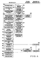
- Fig. 6 shows continuous processing for on-machine plate making and ink film thickness distribution formation by pre-inking 1, which is performed by the main controller 14, on-machine plate making controller 15, and pre-inking controller 27.
- the CPU 14-1 of the main controller 14 reads out the image area ratio of the image to be exposed on the raw plate 5 from the floppy disk set in the drive unit 20 (step S601).
- the CPU 14-1 checks the necessity of a preparatory process (step S602). If the CPU 14-1 starts with a preparatory process, it sends cleaning commands to the inker cleaning controller 22, blanket cleaning controller 23, and impression cylinder clearing unit 24 in accordance with the process shown in Fig. 2A (step S603) to clean the impression cylinder, blanket, and inker.
- the CPU 14-1 also sends paper size/paper thickness preset commands to the paper thickness presetting controller 25 and paper size presetting controller 26 (step S604) to preset a paper size/paper thickness.
- the CPU 14-1 sends a plating change command to the automatic plate change unit 21 (step S605) to change the old printing plate 12 to the raw plate 5.
- the CPU 14-1 sends an entire surface fountain key opening amount set command to the pre-inking controller 27 (step S606) to preset the opening amount of the ink fountain key 9 to a reference opening amount (step S607).
- step S608 The operation based on the commands in steps S603 to 605 corresponds to that in steps S11 to S13 in Fig. 2A.
- step S606 corresponds to that in step S15-1 in Fig. 2A.
- step S609 If the raw plate 5 has already been mounted and the CPU 14-1 is to start with on-machine plate making, it calculates the entire fountain key reference opening amount setting time tp1 (step S609), and the flow advances to step S610.
- step S610 the CPU 14-1 calculates the fountain roller portion basic ink film thickness distribution formation time tp2 and inker portion basic ink film thickness distribution formation time tp3.
- the CPU 14-1 then calculates the fountain key designated opening amount setting time tp4 (step S611) and also calculates the fountain roller portion designated ink film thickness distribution formation time tp5 and inker portion designated ink film thickness distribution formation time tp6 (step S612).
- the CPU 14-1 calculates the time tp taken to form an ink film thickness distribution by pre-inking 1 from the entire fountain key reference opening amount setting time tp1, fountain roller portion basic ink film thickness distribution formation time tp2, inker portion basic ink film thickness distribution formation time tp3, fountain key designated opening amount setting time tp4, fountain roller portion designated ink film thickness distribution formation time tp5, and inker portion designated ink film thickness distribution formation time tp6 (step S613).
- the CPU 14-1 calculates the exposure time tr on the basis of a designated rotational speed in exposure and the size of the raw plate 5 (step S614).
- the CPU 14-1 sends a command to the printing press controller 16 to raise the rotational speed of the printing press to the designated rotational speed in exposure (steps S616 to S618).
- the CPU 14-1 sends an exposure start command to the on-machine plate making controller 15 (step S619).
- the on-machine plate making controller 15 operates the plate making apparatus 2 to start exposing the image on the raw plate 5 (step S620).
- the operation in step S620 corresponds to that in step S14 in Figs. 2A and 2B.
- the CPU 14-1 waits for the calculated pre-inking wait time tw (step S621) and sends a pre-inking 1 start command to the pre-inking controller 27 (step S622). Upon reception of this pre-inking 1 start command, the pre-inking controller 27 performs ink film thickness distribution formation by "pre-inking 1" (step S623).
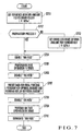
- Fig. 7 shows the processing in step S623 in detail.
- the pre-inking controller 27 presets the rotation amount of the ink fountain roller 8 to a reference rotation amount (step S701). Thereafter, the CPU 14-1 checks the necessity of a preparatory process (step S702).
- the CPU 14-1 When the CPU 14-1 starts with the preparatory process, it sends an ink feed command to the pre-inking controller 27 to enable "ink feed” (step S704). After the ink feed operation of the ink ductor roller 10 is performed eleven times by enabling "ink feed” (step S705), "ink feed” is disabled (step S706). With this operation, the basic ink film thickness distribution Ma is formed on the ink roller group 11.
- the CPU 14-1 sends a data preset command to the pre-inking controller 27 (step S707).
- the opening amount of each of the ink fountain keys 9-1 to 9-n is preset to a value corresponding to the image to be exposed on the raw plate 5, and the rotation amount of the ink fountain roller 8 is preset to a value corresponding to the image to be exposed on the raw plate 5.
- the CPU 14-1 then sends an ink feed command to the pre-inking controller 27 to perform the ink feed operation of the ink ductor roller 10, for example, six times (steps S708 to S710).
- the image ink film thickness distribution Mb is superimposed on the basic ink film thickness distribution Ma formed on the ink roller group 11.
- the operation in steps S701, S702, and S704 to S710 corresponds to that in step S15-2 in Fig. 2A.
- the CPU 14-1 When the preparatory process has already been completed and the CPU 14-1 starts with on-machine plate making, i.e., no preparatory process is to be performed, it sends an entire reference opening amount set command to the pre-inking controller 27 to preset the opening amount of each of the ink fountain keys 9-1 to 9-n to a reference opening amount (step S703).
- the CPU 14-1 then sends an ink feed command to the pre-inking controller 27 to perform the ink feed operation of the ink ductor roller 10, for example, 11 times (steps S704 to S706). With this operation, the basic ink film thickness distribution Ma is formed on the ink roller group 11.
- the CPU 14-1 sends a data preset command for final printing to the pre-inking controller 27 (step S707).
- the opening amount of the ink fountain key 9 is preset to a value corresponding to the image to be exposed on the raw plate 5
- the rotation amount of the ink fountain roller 8 is preset to a value corresponding to the image to be exposed on the raw plate 5.
- the CPU 14-1 sends an ink feed command to the pre-inking controller 27 to perform the ink feed operation of the ink ductor roller 10, for example, six times (steps S708 to S710).
- the image ink film thickness distribution Mb is superimposed on the basic ink film thickness distribution Ma formed on the ink roller group 11.
- the operation in steps S701 to S710 corresponds to that in step S15 in Fig. 2B.
- the on-machine plate making controller 15 sends an exposure end signal to the CPU 14-1 (step S624).
- the pre-inking controller 27 sends a pre-inking 1 end signal to the CPU 14-1 (step S625).
- the CPU 14-1 checks the reception of the exposure end signal from the on-machine plate making controller 15 and the pre-inking 1 end signal from the pre-inking controller 27 (step S626) and starts test printing (step S627). If a satisfactory tone is obtained in this test printing, the flow advances to final printing (step S628).
- exposure and ink film thickness distribution formation by pre-inking 1/pre-inking 2 are simultaneously terminated. However, they need not always be terminated simultaneously. That is, after exposure, ink film thickness distribution formation by pre-inking 1/pre-inking 2 may be terminated with a slight delay. Alternatively, after ink film thickness distribution formation by pre-inking 1/pre-inking 2, exposure may be terminated with a slight delay.
- the opening amount of the ink fountain key 9 is preset to a value corresponding to the image to be exposed on the raw plate 5 during a preparatory process.
- this presetting operation may be performed concurrently with the exposure after the preparatory process.
- the fountain key designated opening amount setting times tp4 and tp1 spent to preset the opening amount of the ink fountain key 9 to a value corresponding to the image to be exposed on the raw plate 5 may be included in the pre-inking time tp.
- an automatic plate change unit is disclosed in Japanese Patent Laid-Open No. 02-258993; an inker cleaning unit, in Japanese Patent Laid-Open Nos. 10-193578 and 10-286944; a blanket cleaning unit, in Japanese Patent Laid-Open Nos. 05-200995 and 09-39215; an impression cylinder cleaning unit, in Japanese Patent Laid-Open Nos. 02-286245 and 03-114748; a paper size presetting unit, in Japanese Patent Laid-Open No. 63-127923; and a paper thickness presetting unit, in Japanese Patent Laid-Open No. 63-134244.
- the techniques disclosed in these references are incorporated in this specification.
- the operation of forming an ink film thickness distribution in the inking device (the operation of forming an ink film thickness distribution on the ink roller group) is performed while exposing of the image on the printing plate (raw plate) is performed, thereby shortening the time spent until final printing is started.
Landscapes
- Inking, Control Or Cleaning Of Printing Machines (AREA)
- Control Of Presses (AREA)
- Exposure And Positioning Against Photoresist Photosensitive Materials (AREA)
Abstract
Description
Claims (12)
- A printing press characterized by comprising:an ink roller group (11) for supplying ink stored in an ink fountain (6) to a printing plate (5) mounted on a plate cylinder (3);image exposing means (15, 28) for exposing an image on a printing plate before plate making which is mounted on the plate cylinder;ink film thickness distribution formation means (27) for forming an ink film thickness distribution corresponding to the image to be exposed on the printing plate on said ink roller group; andcontrol means (14-1) for performing image exposing and ink film thickness distribution formation concurrently at least partly by controlling said image exposing means and said ink film thickness distribution formation means.
- A press according to claim 1, wherein said control means controls to terminate image exposing by said image exposing means and ink film thickness distribution formation by said ink film thickness distribution formation means substantially at the same time.
- A press according to claim 2, whereinsaid control means comprises calculation means (14a) for calculating a wait time between the instant at which image exposing is started and the instant at which ink film thickness distribution formation is started on the basis of a time taken for image exposing by said image exposing means and a time taken for ink film thickness distribution formation by said ink film thickness distribution formation means, andthe ink film thickness distribution formation is started after a lapse of the wait time calculated by said calculation means.
- A press according to claim 3, whereinsaid press further comprises:an ink fountain key (9) for adjusting the amount of ink supplied from the ink fountain; andan ink fountain roller (8) for supplying the ink supplied from the ink fountain via said ink fountain key to said ink roller group, andwhen said ink roller group holds no ink, said calculation means calculates an ink film thickness distribution formation time by adding at least a time taken for basic ink film thickness distribution formation on said ink fountain roller, a time taken for basic ink film thickness distribution formation on said ink roller group, a time taken to set a designated opening amount for said ink fountain key, a time taken for designated ink film thickness distribution formation on said ink fountain roller, and a time taken for designated ink film thickness distribution formation on said ink roller group.
- A press according to claim 3, whereinsaid press further comprises an ink fountain roller (8) for supplying the ink supplied from the ink fountain to said ink roller group, andwhen an old printing plate mounted on the plate cylinder is to be changed to a new printing plate, said calculation means obtains an ink film thickness distribution formation time by adding at least a time taken for designated ink film thickness distribution formation on said ink fountain roller and a time taken for designated ink film thickness distribution formation on said ink roller group.
- A press according to claim 3, wherein when a preparatory process including at least one of ink removing, cleaning of an impression cylinder and a blanket, paper size/paper thickness presetting, and plate change is not performed before image exposing, said calculation means calculates an ink film thickness distribution formation time including a time taken to set a designated opening amount for said ink fountain key.
- A control method for a printing press including an ink roller group (11) for supplying ink stored in an ink fountain (6) to a printing plate (5) mounted on a plate cylinder (3), characterized by comprising the steps of:exposing an image on a printing plate before plate making which is mounted on the plate cylinder;forming an ink film thickness distribution corresponding to the image to be exposed on the printing plate on the ink roller group; andcontrolling to perform image exposing and ink film thickness distribution formation concurrently at least partly.
- A method according to claim 7, wherein the control step comprises the step of terminating image exposing and ink film thickness distribution formation substantially at the same time.
- A method according to claim 8, whereinthe control step comprises the steps of:calculating a wait time between the instant at which image exposing is started and the instant at which ink film thickness distribution formation is started on the basis of a time taken for image exposing and a time taken for ink film thickness distribution formation, andstarting the ink film thickness distribution formation when the calculated wait time elapses after image exposing is started.
- A method according to claim 9, wherein the step of calculating comprises, when the ink roller group holds no ink, the step of obtaining an ink film thickness distribution formation time by adding at least a time taken for basic ink film thickness distribution formation on the ink fountain roller (8) for supplying the ink, supplied from the ink fountain for which an amount of ink to be supplied is adjusted by an ink fountain key (9), to the ink roller group, a time taken for basic ink film thickness distribution formation on the ink roller group, a time taken to set a designated opening amount for the ink fountain key, a time taken for designated ink film thickness distribution formation on the ink fountain roller, and a time taken for designated ink film thickness distribution formation on the ink roller group.
- A method according to claim 9, wherein the step of calculating comprises the step of obtaining, when an old printing plate mounted on the plate cylinder is to be changed to a new printing plate, an ink film thickness distribution formation time by adding at least a time taken for designated ink film thickness distribution formation on an ink fountain roller (8) for supplying the ink, supplied from the ink fountain for which an amount of ink to be supplied is adjusted by an ink fountain key (9), to the ink roller group and a time taken for designated ink film thickness distribution formation on the ink roller group.
- A method according to claim 9, wherein the step of calculating comprises the step of, when a preparatory process including at least one of ink removing, cleaning of an impression cylinder and a blanket, paper size/paper thickness presetting, and plate change is not performed before image exposing, calculating an ink film thickness distribution formation time including a time taken to set a designated opening amount for the ink fountain key.
Applications Claiming Priority (2)
| Application Number | Priority Date | Filing Date | Title |
|---|---|---|---|
| JP2000145549 | 2000-05-17 | ||
| JP2000145549A JP2001322250A (en) | 2000-05-17 | 2000-05-17 | Printing press and control method for the printing press |
Publications (3)
| Publication Number | Publication Date |
|---|---|
| EP1157839A2 true EP1157839A2 (en) | 2001-11-28 |
| EP1157839A3 EP1157839A3 (en) | 2002-09-11 |
| EP1157839B1 EP1157839B1 (en) | 2007-08-01 |
Family
ID=18652040
Family Applications (1)
| Application Number | Title | Priority Date | Filing Date |
|---|---|---|---|
| EP01250172A Expired - Lifetime EP1157839B1 (en) | 2000-05-17 | 2001-05-16 | Printing press and printing press control method |
Country Status (6)
| Country | Link |
|---|---|
| US (1) | US6615728B2 (en) |
| EP (1) | EP1157839B1 (en) |
| JP (1) | JP2001322250A (en) |
| AT (1) | ATE368570T1 (en) |
| DE (1) | DE60129636T2 (en) |
| ES (1) | ES2290088T3 (en) |
Families Citing this family (6)
| Publication number | Priority date | Publication date | Assignee | Title |
|---|---|---|---|---|
| JP4128866B2 (en) * | 2002-12-26 | 2008-07-30 | 株式会社小森コーポレーション | Ink supply amount control method and apparatus for printing press |
| JP4064882B2 (en) * | 2003-07-07 | 2008-03-19 | リョービ株式会社 | Ink quantity control device for printing press |
| JP5897853B2 (en) * | 2011-09-12 | 2016-04-06 | 株式会社小森コーポレーション | Method and apparatus for forming ink film thickness distribution |
| JP5897852B2 (en) | 2011-09-12 | 2016-04-06 | 株式会社小森コーポレーション | Method and apparatus for correcting ink film thickness distribution |
| JP6093152B2 (en) * | 2012-11-12 | 2017-03-08 | 株式会社小森コーポレーション | Ink supply method and ink supply apparatus |
| JP6093151B2 (en) * | 2012-11-12 | 2017-03-08 | 株式会社小森コーポレーション | Method and apparatus for correcting ink film thickness distribution |
Family Cites Families (19)
| Publication number | Priority date | Publication date | Assignee | Title |
|---|---|---|---|---|
| JP2582359B2 (en) | 1986-11-19 | 1997-02-19 | 三菱重工業株式会社 | Paper size preset control device for sheet-fed printing press |
| JPS63134244A (en) | 1986-11-27 | 1988-06-06 | Mitsubishi Heavy Ind Ltd | Printing pressure setting controller for sheet-feed press |
| US5237923A (en) * | 1988-08-19 | 1993-08-24 | Presstek, Inc. | Apparatus and method for imaging lithographic printing plates using spark discharges |
| JP2884348B2 (en) | 1989-03-30 | 1999-04-19 | 東邦チタニウム株式会社 | Electrolyzer for metal production |
| DE3911932A1 (en) * | 1989-04-12 | 1990-10-25 | Krause Biagosch Gmbh | Rotary printing machine - with built in preparatory facility to produce printing cylinders |
| JPH02286245A (en) | 1989-04-26 | 1990-11-26 | Nippon Baldwin Kk | Cylinder cleaning device for sheet-fed printing presses |
| JPH03114748A (en) | 1990-08-29 | 1991-05-15 | Nippon Baldwin Kk | Cylinder cleaning device in printing press |
| JP3114748B2 (en) | 1991-09-30 | 2000-12-04 | 株式会社神戸製鋼所 | Output control device for welding power supply |
| JP3180163B2 (en) | 1992-01-27 | 2001-06-25 | 株式会社小森コーポレーション | Cylinder cleaning device for printing machine and its cleaning method |
| US5379698A (en) | 1992-07-20 | 1995-01-10 | Presstek, Inc. | Lithographic printing members for use with laser-discharge imaging |
| DE19506425B4 (en) * | 1995-02-24 | 2004-11-18 | Heidelberger Druckmaschinen Ag | Offset printing process |
| JP3604785B2 (en) | 1995-07-26 | 2004-12-22 | 株式会社小森コーポレーション | Printing machine cylinder cleaning device |
| EP0771646A3 (en) * | 1995-10-31 | 1999-08-11 | Dainippon Screen Mfg. Co., Ltd. | Digital printer |
| JPH1016193A (en) | 1996-06-27 | 1998-01-20 | Komori Corp | Control method of ink film thickness |
| JPH10193578A (en) | 1997-01-08 | 1998-07-28 | Komori Corp | Cleaning equipment for rotary printing presses |
| JP3466867B2 (en) * | 1997-03-28 | 2003-11-17 | 大日本スクリーン製造株式会社 | Printing equipment |
| JPH10286944A (en) | 1997-04-14 | 1998-10-27 | Komori Corp | Cleaning equipment for rotary printing presses |
| DE19743770A1 (en) * | 1997-10-02 | 1999-04-08 | Heidelberger Druckmasch Ag | Method for operating a rotary printing press and device for carrying out the method |
| JP4490512B2 (en) * | 1997-12-26 | 2010-06-30 | 株式会社小森コーポレーション | Ink film thickness control method and control apparatus |
-
2000
- 2000-05-17 JP JP2000145549A patent/JP2001322250A/en active Pending
-
2001
- 2001-05-16 ES ES01250172T patent/ES2290088T3/en not_active Expired - Lifetime
- 2001-05-16 EP EP01250172A patent/EP1157839B1/en not_active Expired - Lifetime
- 2001-05-16 AT AT01250172T patent/ATE368570T1/en not_active IP Right Cessation
- 2001-05-16 DE DE60129636T patent/DE60129636T2/en not_active Expired - Lifetime
- 2001-05-17 US US09/860,066 patent/US6615728B2/en not_active Expired - Fee Related
Also Published As
| Publication number | Publication date |
|---|---|
| DE60129636T2 (en) | 2008-05-21 |
| JP2001322250A (en) | 2001-11-20 |
| US20010042484A1 (en) | 2001-11-22 |
| ATE368570T1 (en) | 2007-08-15 |
| US6615728B2 (en) | 2003-09-09 |
| EP1157839A3 (en) | 2002-09-11 |
| ES2290088T3 (en) | 2008-02-16 |
| DE60129636D1 (en) | 2007-09-13 |
| EP1157839B1 (en) | 2007-08-01 |
Similar Documents
| Publication | Publication Date | Title |
|---|---|---|
| EP0816075B1 (en) | Ink film thickness control method for ink supply apparatus | |
| CA2013363C (en) | Method of operating a printing machine during start-up or run-on | |
| EP0897799B1 (en) | Automatic control of plate mounting, ink presetting and cylinder cleaning in a printing press | |
| EP0983852B1 (en) | Ink film thickness control method and apparatus for multi-color printing press | |
| EP1157839B1 (en) | Printing press and printing press control method | |
| JPH08183167A (en) | Method for forming ink film thickness suitable for running-on in inking unit | |
| US8746143B2 (en) | Method and apparatus for compensating for inking differences in printing presses with an anilox short inking unit and printing press having the apparatus | |
| EP1155853B1 (en) | Printing press and printing press control method | |
| US5029526A (en) | Method and apparatus for setting the starting time of transverse ink distribution for printing machines | |
| JP3073609B2 (en) | How to adjust ink distribution during regular printing of offset printing press | |
| EP1302317B1 (en) | Method of presetting ink | |
| EP1302318B1 (en) | Printing apparatus | |
| JP2003334928A (en) | Ink supply control device | |
| JP2000108308A (en) | Apparatus and method for presetting color tone in printing | |
| JPH11188849A (en) | Method and apparatus for controlling ink film thickness | |
| US6378431B1 (en) | Printing machine having a plurality of printing units for overprinting a plurality of inks in one pass | |
| JP4192507B2 (en) | Integrated printing color tone control method and apparatus | |
| JP3752111B2 (en) | On-press plate-fed printing press | |
| CN102756552A (en) | Method for mixing colors between two successive print jobs | |
| US20090199730A1 (en) | Apparatus and method for driving a printing press | |
| JP4354444B2 (en) | Plate making method and apparatus | |
| JPH11240141A (en) | Halftone dot inking control device | |
| JPH11188848A (en) | Method and apparatus for controlling ink film thickness | |
| JP2001353838A (en) | Method for controlling fountain liquid of printing press | |
| WO2011035316A1 (en) | Method of phasing and accelerating cylinders of a printing press during auto transfer |
Legal Events
| Date | Code | Title | Description |
|---|---|---|---|
| PUAI | Public reference made under article 153(3) epc to a published international application that has entered the european phase |
Free format text: ORIGINAL CODE: 0009012 |
|
| 17P | Request for examination filed |
Effective date: 20010613 |
|
| AK | Designated contracting states |
Kind code of ref document: A2 Designated state(s): AT BE CH CY DE DK ES FI FR GB GR IE IT LI LU MC NL PT SE TR |
|
| AX | Request for extension of the european patent |
Free format text: AL;LT;LV;MK;RO;SI |
|
| PUAL | Search report despatched |
Free format text: ORIGINAL CODE: 0009013 |
|
| AK | Designated contracting states |
Kind code of ref document: A3 Designated state(s): AT BE CH CY DE DK ES FI FR GB GR IE IT LI LU MC NL PT SE TR |
|
| AX | Request for extension of the european patent |
Free format text: AL;LT;LV;MK;RO;SI |
|
| RIC1 | Information provided on ipc code assigned before grant |
Free format text: 7B 41F 33/00 A, 7B 41F 31/00 B, 7B 41C 1/00 B, 7B 41C 1/10 B |
|
| AKX | Designation fees paid |
Designated state(s): AT BE CH CY DE DK ES FI FR GB GR IE IT LI LU MC NL PT SE TR |
|
| 17Q | First examination report despatched |
Effective date: 20050426 |
|
| GRAP | Despatch of communication of intention to grant a patent |
Free format text: ORIGINAL CODE: EPIDOSNIGR1 |
|
| GRAS | Grant fee paid |
Free format text: ORIGINAL CODE: EPIDOSNIGR3 |
|
| GRAA | (expected) grant |
Free format text: ORIGINAL CODE: 0009210 |
|
| AK | Designated contracting states |
Kind code of ref document: B1 Designated state(s): AT BE CH CY DE DK ES FI FR GB GR IE IT LI LU MC NL PT SE TR |
|
| REG | Reference to a national code |
Ref country code: GB Ref legal event code: FG4D |
|
| REG | Reference to a national code |
Ref country code: CH Ref legal event code: EP |
|
| REG | Reference to a national code |
Ref country code: IE Ref legal event code: FG4D |
|
| REF | Corresponds to: |
Ref document number: 60129636 Country of ref document: DE Date of ref document: 20070913 Kind code of ref document: P |
|
| REG | Reference to a national code |
Ref country code: SE Ref legal event code: TRGR |
|
| REG | Reference to a national code |
Ref country code: CH Ref legal event code: NV Representative=s name: LUCHS & PARTNER PATENTANWAELTE |
|
| ET | Fr: translation filed | ||
| PG25 | Lapsed in a contracting state [announced via postgrant information from national office to epo] |
Ref country code: FI Free format text: LAPSE BECAUSE OF FAILURE TO SUBMIT A TRANSLATION OF THE DESCRIPTION OR TO PAY THE FEE WITHIN THE PRESCRIBED TIME-LIMIT Effective date: 20070801 |
|
| REG | Reference to a national code |
Ref country code: ES Ref legal event code: FG2A Ref document number: 2290088 Country of ref document: ES Kind code of ref document: T3 |
|
| PG25 | Lapsed in a contracting state [announced via postgrant information from national office to epo] |
Ref country code: AT Free format text: LAPSE BECAUSE OF FAILURE TO SUBMIT A TRANSLATION OF THE DESCRIPTION OR TO PAY THE FEE WITHIN THE PRESCRIBED TIME-LIMIT Effective date: 20070801 |
|
| PG25 | Lapsed in a contracting state [announced via postgrant information from national office to epo] |
Ref country code: BE Free format text: LAPSE BECAUSE OF FAILURE TO SUBMIT A TRANSLATION OF THE DESCRIPTION OR TO PAY THE FEE WITHIN THE PRESCRIBED TIME-LIMIT Effective date: 20070801 |
|
| PG25 | Lapsed in a contracting state [announced via postgrant information from national office to epo] |
Ref country code: DK Free format text: LAPSE BECAUSE OF FAILURE TO SUBMIT A TRANSLATION OF THE DESCRIPTION OR TO PAY THE FEE WITHIN THE PRESCRIBED TIME-LIMIT Effective date: 20070801 Ref country code: GR Free format text: LAPSE BECAUSE OF FAILURE TO SUBMIT A TRANSLATION OF THE DESCRIPTION OR TO PAY THE FEE WITHIN THE PRESCRIBED TIME-LIMIT Effective date: 20071102 |
|
| PG25 | Lapsed in a contracting state [announced via postgrant information from national office to epo] |
Ref country code: PT Free format text: LAPSE BECAUSE OF FAILURE TO SUBMIT A TRANSLATION OF THE DESCRIPTION OR TO PAY THE FEE WITHIN THE PRESCRIBED TIME-LIMIT Effective date: 20080102 |
|
| PLBE | No opposition filed within time limit |
Free format text: ORIGINAL CODE: 0009261 |
|
| STAA | Information on the status of an ep patent application or granted ep patent |
Free format text: STATUS: NO OPPOSITION FILED WITHIN TIME LIMIT |
|
| 26N | No opposition filed |
Effective date: 20080506 |
|
| PG25 | Lapsed in a contracting state [announced via postgrant information from national office to epo] |
Ref country code: MC Free format text: LAPSE BECAUSE OF NON-PAYMENT OF DUE FEES Effective date: 20080531 |
|
| PG25 | Lapsed in a contracting state [announced via postgrant information from national office to epo] |
Ref country code: IE Free format text: LAPSE BECAUSE OF NON-PAYMENT OF DUE FEES Effective date: 20080516 |
|
| PG25 | Lapsed in a contracting state [announced via postgrant information from national office to epo] |
Ref country code: CY Free format text: LAPSE BECAUSE OF FAILURE TO SUBMIT A TRANSLATION OF THE DESCRIPTION OR TO PAY THE FEE WITHIN THE PRESCRIBED TIME-LIMIT Effective date: 20070801 |
|
| PGFP | Annual fee paid to national office [announced via postgrant information from national office to epo] |
Ref country code: ES Payment date: 20090609 Year of fee payment: 9 Ref country code: NL Payment date: 20090517 Year of fee payment: 9 |
|
| PGFP | Annual fee paid to national office [announced via postgrant information from national office to epo] |
Ref country code: FR Payment date: 20090515 Year of fee payment: 9 Ref country code: IT Payment date: 20090519 Year of fee payment: 9 Ref country code: SE Payment date: 20090512 Year of fee payment: 9 |
|
| PGFP | Annual fee paid to national office [announced via postgrant information from national office to epo] |
Ref country code: CH Payment date: 20090513 Year of fee payment: 9 |
|
| PGFP | Annual fee paid to national office [announced via postgrant information from national office to epo] |
Ref country code: GB Payment date: 20090513 Year of fee payment: 9 |
|
| PG25 | Lapsed in a contracting state [announced via postgrant information from national office to epo] |
Ref country code: LU Free format text: LAPSE BECAUSE OF NON-PAYMENT OF DUE FEES Effective date: 20080516 |
|
| PG25 | Lapsed in a contracting state [announced via postgrant information from national office to epo] |
Ref country code: TR Free format text: LAPSE BECAUSE OF FAILURE TO SUBMIT A TRANSLATION OF THE DESCRIPTION OR TO PAY THE FEE WITHIN THE PRESCRIBED TIME-LIMIT Effective date: 20070801 |
|
| PGFP | Annual fee paid to national office [announced via postgrant information from national office to epo] |
Ref country code: DE Payment date: 20100512 Year of fee payment: 10 |
|
| REG | Reference to a national code |
Ref country code: NL Ref legal event code: V1 Effective date: 20101201 |
|
| REG | Reference to a national code |
Ref country code: CH Ref legal event code: PL |
|
| GBPC | Gb: european patent ceased through non-payment of renewal fee |
Effective date: 20100516 |
|
| EUG | Se: european patent has lapsed | ||
| REG | Reference to a national code |
Ref country code: FR Ref legal event code: ST Effective date: 20110131 |
|
| PG25 | Lapsed in a contracting state [announced via postgrant information from national office to epo] |
Ref country code: CH Free format text: LAPSE BECAUSE OF NON-PAYMENT OF DUE FEES Effective date: 20100531 Ref country code: LI Free format text: LAPSE BECAUSE OF NON-PAYMENT OF DUE FEES Effective date: 20100531 |
|
| PG25 | Lapsed in a contracting state [announced via postgrant information from national office to epo] |
Ref country code: IT Free format text: LAPSE BECAUSE OF NON-PAYMENT OF DUE FEES Effective date: 20100516 Ref country code: NL Free format text: LAPSE BECAUSE OF NON-PAYMENT OF DUE FEES Effective date: 20101201 Ref country code: SE Free format text: LAPSE BECAUSE OF NON-PAYMENT OF DUE FEES Effective date: 20100517 |
|
| PG25 | Lapsed in a contracting state [announced via postgrant information from national office to epo] |
Ref country code: FR Free format text: LAPSE BECAUSE OF NON-PAYMENT OF DUE FEES Effective date: 20100531 |
|
| REG | Reference to a national code |
Ref country code: ES Ref legal event code: FD2A Effective date: 20110714 |
|
| PG25 | Lapsed in a contracting state [announced via postgrant information from national office to epo] |
Ref country code: GB Free format text: LAPSE BECAUSE OF NON-PAYMENT OF DUE FEES Effective date: 20100516 Ref country code: ES Free format text: LAPSE BECAUSE OF NON-PAYMENT OF DUE FEES Effective date: 20110704 |
|
| PG25 | Lapsed in a contracting state [announced via postgrant information from national office to epo] |
Ref country code: ES Free format text: LAPSE BECAUSE OF NON-PAYMENT OF DUE FEES Effective date: 20100517 |
|
| REG | Reference to a national code |
Ref country code: DE Ref legal event code: R119 Ref document number: 60129636 Country of ref document: DE |
|
| REG | Reference to a national code |
Ref country code: DE Ref legal event code: R119 Ref document number: 60129636 Country of ref document: DE |
|
| PG25 | Lapsed in a contracting state [announced via postgrant information from national office to epo] |
Ref country code: DE Free format text: LAPSE BECAUSE OF NON-PAYMENT OF DUE FEES Effective date: 20111130 |