EP1157837B1 - Method for registration in a multi-colour printing press - Google Patents
Method for registration in a multi-colour printing press Download PDFInfo
- Publication number
- EP1157837B1 EP1157837B1 EP01110797A EP01110797A EP1157837B1 EP 1157837 B1 EP1157837 B1 EP 1157837B1 EP 01110797 A EP01110797 A EP 01110797A EP 01110797 A EP01110797 A EP 01110797A EP 1157837 B1 EP1157837 B1 EP 1157837B1
- Authority
- EP
- European Patent Office
- Prior art keywords
- image
- areas
- register
- printing
- correction values
- Prior art date
- Legal status (The legal status is an assumption and is not a legal conclusion. Google has not performed a legal analysis and makes no representation as to the accuracy of the status listed.)
- Expired - Lifetime
Links
Images


Classifications
-
- H—ELECTRICITY
- H04—ELECTRIC COMMUNICATION TECHNIQUE
- H04N—PICTORIAL COMMUNICATION, e.g. TELEVISION
- H04N1/00—Scanning, transmission or reproduction of documents or the like, e.g. facsimile transmission; Details thereof
- H04N1/46—Colour picture communication systems
- H04N1/50—Picture reproducers
- H04N1/506—Reproducing the colour component signals picture-sequentially, e.g. with reproducing heads spaced apart from one another in the subscanning direction
-
- B—PERFORMING OPERATIONS; TRANSPORTING
- B41—PRINTING; LINING MACHINES; TYPEWRITERS; STAMPS
- B41F—PRINTING MACHINES OR PRESSES
- B41F13/00—Common details of rotary presses or machines
- B41F13/08—Cylinders
- B41F13/10—Forme cylinders
- B41F13/12—Registering devices
- B41F13/14—Registering devices with means for displacing the cylinders
-
- B—PERFORMING OPERATIONS; TRANSPORTING
- B41—PRINTING; LINING MACHINES; TYPEWRITERS; STAMPS
- B41F—PRINTING MACHINES OR PRESSES
- B41F33/00—Indicating, counting, warning, control or safety devices
- B41F33/0081—Devices for scanning register marks
-
- G—PHYSICS
- G03—PHOTOGRAPHY; CINEMATOGRAPHY; ANALOGOUS TECHNIQUES USING WAVES OTHER THAN OPTICAL WAVES; ELECTROGRAPHY; HOLOGRAPHY
- G03G—ELECTROGRAPHY; ELECTROPHOTOGRAPHY; MAGNETOGRAPHY
- G03G15/00—Apparatus for electrographic processes using a charge pattern
- G03G15/01—Apparatus for electrographic processes using a charge pattern for producing multicoloured copies
- G03G15/0142—Structure of complete machines
- G03G15/0178—Structure of complete machines using more than one reusable electrographic recording member, e.g. one for every monocolour image
- G03G15/0194—Structure of complete machines using more than one reusable electrographic recording member, e.g. one for every monocolour image primary transfer to the final recording medium
-
- B—PERFORMING OPERATIONS; TRANSPORTING
- B41—PRINTING; LINING MACHINES; TYPEWRITERS; STAMPS
- B41P—INDEXING SCHEME RELATING TO PRINTING, LINING MACHINES, TYPEWRITERS, AND TO STAMPS
- B41P2233/00—Arrangements for the operation of printing presses
- B41P2233/50—Marks on printed material
- B41P2233/52—Marks on printed material for registering
-
- G—PHYSICS
- G03—PHOTOGRAPHY; CINEMATOGRAPHY; ANALOGOUS TECHNIQUES USING WAVES OTHER THAN OPTICAL WAVES; ELECTROGRAPHY; HOLOGRAPHY
- G03G—ELECTROGRAPHY; ELECTROPHOTOGRAPHY; MAGNETOGRAPHY
- G03G2215/00—Apparatus for electrophotographic processes
- G03G2215/01—Apparatus for electrophotographic processes for producing multicoloured copies
- G03G2215/0103—Plural electrographic recording members
- G03G2215/0119—Linear arrangement adjacent plural transfer points
-
- G—PHYSICS
- G03—PHOTOGRAPHY; CINEMATOGRAPHY; ANALOGOUS TECHNIQUES USING WAVES OTHER THAN OPTICAL WAVES; ELECTROGRAPHY; HOLOGRAPHY
- G03G—ELECTROGRAPHY; ELECTROPHOTOGRAPHY; MAGNETOGRAPHY
- G03G2215/00—Apparatus for electrophotographic processes
- G03G2215/01—Apparatus for electrophotographic processes for producing multicoloured copies
- G03G2215/0151—Apparatus for electrophotographic processes for producing multicoloured copies characterised by the technical problem
- G03G2215/0158—Colour registration
- G03G2215/0161—Generation of registration marks
Definitions
- the invention relates to a method for register setting on a multi-color printing machine with different printing colors associated color printing units, at least one image cylinder, image forming means for generating partial color images, in particular of electrostatic latent part color images on the at least one image cylinder, a support for printing substrates and at least one image transfer point for the transfer of Part color images on the printing substrates, wherein an association of the image forming locations on the at least one image cylinder to achieve registration of the partial color images in printing is performed by both generating the image starts and generating regions of the partial color images based on the pressure and the evaluation of register marks is set.
- a device is described according to the above-mentioned method for register setting on a multi-color printing press with color printing units associated with different inks, at least one image cylinder, image forming devices for producing partial color images, in particular electrostatic latent partial color images on the at least one image cylinder, a substrate for printing substrates and at least one image transfer point for transferring the partial color images to printing substrates, position detecting sensors, and at least one adjusting means for associating the positions of the image forming sites on the at least one image cylinder to achieve register matching of the partial color images in printing, at least one register sensor arranged to detect register marks and forming the adjustment device is that it causes the printing of register marks and evaluates on such basis that it stops the generation of the image starts as well as the generation of areas of the part color images.
- the printing of color representations takes place in that several partial color images are printed one above the other. These are usually the colors yellow, magenta and cyan as well as black. If necessary, special colors are added. By overprinting these colors, all color compositions can be achieved.
- the quality of the prints depends essentially on the register-containing overprinting of the partial color images. In conventional printing methods, the printing forms are corrected by means of trial prints and register marks printed therewith until an exact overprinting, that is a registration of the print, is achieved.
- the image cylinders are each described by means of an image-forming device with pixels, for example, by generating electrostatic charges and providing them with adhering color pigments. Thereafter, the color pigments are transferred to a printing substrate.
- registration can be achieved by controlling the image forming devices accordingly. Since the image is reprinted for each print, it is not necessary to make a one-time adjustment as in the conventional printing methods, but it is possible to provide a preset and a control which makes corrections for each individual print. Of course, this not only applies to the application of electrostatic latent images but also all other printing processes in which pixels are applied by means of a digital control.
- EP-A-0770480 discloses, as prior art, a digital printing machine with multiple printing units and with an automatic register control.
- the document US-A-4719575 describes a method for maintaining the registers in a web-conveying machine with cross-cutting device.
- the invention is therefore based on the object, a method of the type mentioned in such a way that the register setting with reasonable computational effort and high accuracy can be realized and the data can be obtained and processed with reasonable computational effort.
- At least one image page is printed with register marks, which has a different length than the prints whose register is to be set, and that in order to determine the correction values, the data of the register marks of the at least one image page is acquired, to positions of image markers. and substrate-carrying elements, and the image-forming devices are controlled according to the correction values.
- the invention has the advantage that it provides a method by which the correction values can be determined from the actual and desired values within a short time and the corrections can be carried out with a reasonable computational effort.
- the basic idea of the invention consists in the separability of the actual values of the image beginnings from the actual values of the regions of the partial color images by the proposed configuration of register marks. This separation can be carried out as an intermediate step, for example for the computational determination of the correction values for the image generations, or separate correction values can be determined and taken into account.
- At least one proof be printed in which an image page is printed with register marks, which is longer than the prints whose registers are to be set or if several pages are created, that these are shorter than the prints, whose registers are to be set.
- Such length deviations make it possible to eliminate the errors of Image starts, which are due to a mapping error of the image generations to each other, to be separated from the errors of the image areas resulting from transmission errors of the generated partial color images of the image formation to its transfer to a printing substrate.
- These different causes of the errors makes it possible to separate them, since the linking of the errors of the image beginnings to the errors of the regions of the partial color images can be eliminated by the image pages with register marks of different lengths from the prints to be created.
- This separation is required, at least within the calculation of correction values, in order to realize a register setting with reasonable computation and high accuracy.
- the separation to be performed at least as an intermediate calculation step is possible because of the different characteristics of the errors, since the error of the areas of the partial color images occurs as a substantially periodic curve and the error of the image starts as a non-zero axis section (offset) of this curve can be detected.
- the difficulty of this detection is that even the mean value of the curve does not have a straight course in reality.
- the detected curve may be a superposition of two curves which must be separated to detect the errors of the image starts and the errors of the regions of the part color images. This can for example be done by a computer that recognizes the characteristics due to an algorithm. This separation is made possible by the different length of the image page or image pages to the prints to be created, because the calculation is possible with less unknown and simpler vorappelbar.
- the assignment of the image generations to positions of the image cylinders can be made such that both the image beginnings and the regions of the partial color images arrive at their desired position on the carrier or on a printing substrate located on the latter.
- the assignment of the data of the register marks to positions of the image and substrate-carrying elements can be effected as a direct position assignment or as an indirect position assignment over detected times.
- a further development of the method provides that the data of the register marks are related to the positions of the image cylinders and of the carrier and the image-forming devices on the image cylinders are controlled in order to obtain the desired values on the carrier.
- the at least one adjusting means is arranged to relate the data register marks to positions of the image cylinders and the carrier, thereby controlling the image forming means on the image cylinders to obtain the set values on the carrier.
- This embodiment is especially for multi-color printing machines in which the partial color images are transferred directly from the image cylinders on printing substrates, which are located on a support.
- the data of the register marks are also related to positions of the image transfer cylinders and included in the control of the image forming devices
- the at least one adjusting device is designed such that it also relates the data of the register marks to positions of the image transfer cylinders and involves them in the control of the image generating devices. This measure is particularly important because of the required contact of Image cylinder and image transfer cylinder at least one of the surfaces may have a certain elasticity.
- the image transfer cylinders are equipped with an elastic jacket.
- the method is expediently designed such that separate correction values for the generation of the image beginnings and the regions of the partial color images are determined, the generation of the regions being based on the image beginnings.
- the at least one adjusting device is designed in a corresponding manner. If a start of the image is exactly positioned in the case of a corresponding control, then the areas of the partial color images can adjoin it, wherein each individual area can be positioned corresponding to the correction values for the areas of the partial color images.
- the at least one image page with register marks can have an excess length, in which case under certain circumstances a single image page is sufficient for determining the correction values. Another possibility is that more than the prints whose registers are to be set, shorter image pages are created. In the former case, it is convenient if the length of an image page is selected such that a plurality of periods of errors of regions of the color images are detected. In the second case, it is expedient if the shorter picture pages are positioned in such a way that they contain a plurality of periods of errors of picture beginnings.
- the at least one adjustment device is designed for evaluation in the aforementioned ways.
- the register marks are designed such that the actual positions of the image beginnings can be detected from them and that the correction values are determined from a comparison of the actual and desired positions. Furthermore, it is proposed that the register marks are formed such that the actual positions of the regions can be detected from them and that the correction values are determined from a comparison of the actual and desired positions. With respect to the device, it is proposed that it is designed such that it determines the correction values from the data of the detected register marks in the aforementioned manner.
- the areas of the partial color images may be pixel rows or groups of pixel rows.
- the device is then designed to calculate areas that may be pixel rows or groups of pixel rows.
- the position allocation can be made indirectly via a time allocation, or it can be made directly as a position assignment.
- the device is proposed that it is equipped with at least one sensor for at least one position detection and so is formed so that it assigns the position of the areas defined angular positions of the image cylinder. It is particularly expedient to define angular sequences of the image cylinder fixed and assign these defined angular sequences the sizes of the areas. For a corresponding assignment, the device is formed.
- This assignment to defined angular sequences of the image cylinders is a simple method for eliminating different transfers of the regions in different positions of the elements transferring them in the production of the partial color images in such a way that the registration accuracy on the printing substrate is subsequently ensured.
- a simple correction of the size of the areas can be made by changing the pitch of the pixel rows.
- the method is configured in such a way that the data of the register marks are used to separately record the actual values of the image beginnings and the actual values of the regions of the partial color images by separating the data obtained by detecting the register marks by means of corresponding algorithms on the basis of their different characteristics.
- the apparatus include a computer loaded with algorithms by which it separates data obtained by detecting the register marks based on the different characteristics of the actual values of the image starts and the actual values of the areas.
- the inventive measure with the different lengths of the image pages to the prints offers the advantage that the calculation can be made with reasonable effort and fast enough. Situations, in where such a separation is not possible, are excluded by the inventive measures.
- the test print of the at least one image page for carrying out a presetting of a register before the printing of a printing substrate is carried out and the calculation serves to ensure that already the first printed substrate is fully in register.
- the inventive calculation of the correction values offers the great advantage that machines can be designed in such a way that even different individual pages can be printed in register. It is useful if the proof printed on the support for printing substrates and removed after the evaluation again.
- the apparatus is provided with means for removing sample prints of image pages from the support.
- a proof for a register control can also be done during the printing of the printing substrates, the proofs can be applied, for example, not covered by printing substrates surfaces of the support for printing substrates and removed again after the evaluation.
- This measure has the advantage, for example, that a drift correction is detected during the pressure and counter-control can be promptly performed by corresponding correction values.
- Fig. 1 shows the principle of a multi-color printing machine 1, the register can be adjusted according to the invention.
- a multi-color printing machine 1 usually consists of four or more color printing units 6, 6 ', 6 ", 6"'. For simplicity, only two color printing units 6 and 6 'have been shown.
- These partial color images 7, 7 ',... Are transferred from the image cylinders 2, 2',... Onto image transfer cylinders 13, 13 ',..., And then transferred to printing substrates 15 from these image transfer cylinders 13, 13', to get upset.
- the prints 14 whose registers are to be adjusted have image beginnings 10 and are divided into regions 10 ', 10 ", ..., 10 n , this division being made for each partial color image 7, 7' in order to produce the regions 10 , 10 ', 10 ", ..., 10 n in such a way that a register-accurate overprinting of both the image beginnings 10 and the areas 10', 10", ..., 10 n can be achieved.
- the devices 3, 3 'are, ... is controlled such that the image forming points 11, 11', ..., the image starts 10 and the areas 10 ', 10 ", ..., 10 n in such positions of the image cylinder 2, 2 ', ... place that the partial color images 7, 7', ... with respect to all defined areas 10, 10 ', 10 ", ..., 10 n printed on each other.
- sensors 20 for the position detection of all image and substrate-carrying elements 2, 2 ', ..., 4, 13, 13', ... are provided.
- a sensor 21 for the detection of printing substrates 15 is provided, which gives a corresponding message to the adjusting devices 22, 22 ', 22 ", 22'".
- the printing substrates 15 are transported in the direction of the arrow 26 by a support 4 for printing substrates 15 and at each color printing unit 6, 6 'at an image transfer point 5' with a partial color image 7, 7 ', ... provided.
- the image transfer points 5, 5 ', ... opposite, so on the other side of the carrier 4, are still impression cylinder, the mechanical and electrostatic support the transfer of the partial color images 7, 7', ... on the printing substrates 15. These impression cylinders are not shown for the sake of simplicity.
- the illustrated embodiment of the invention proposes to assign the defined regions 10, 10 ', 10 ",..., 10 n of the partial color images 7, 7',... Defined angular positions 18 of the image cylinders 2, 2 ', in that each region 10, 10 ', 10 ", ..., 10 n is associated with a defined angular sequence 19 of the respective image cylinder 2, 2',.
- the defined angular sequences 19 and the defined regions 10, 10 ', 10 ", ..., 10 n are drawn much larger than actually realized, and the latter would be so small that they can not be represented graphically in this way A subdivision of the greatest fineness is necessary for the achievement of quality prints.
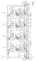
- Fig. 2 shows an embodiment of a multi-color printing machine 1 with the realization of a register setting according to the invention.
- each color printing unit 6, 6 ', 6 ", 6"' is assigned an adjustment device 22, 22 ', 22 ", 22"' which comprises the devices 3, 3 ',...
- For generating the partial color images 7, 7 ', ... controls so that the image forming stations 11, 11', ... are placed on the image cylinders 2, 2 ', ... such that the partial color images 7, 7',.. a printing substrate 15 are printed in register over each other.
- the invention provides that prior to the creation of a print 14 whose register is set, that is, before a printing substrate 15 passes through the machine, are printed as a trial print image pages 8, 8 'on the support 4 for printing substrates 15, the register marks 9, 9 ', 9 ", 9"' included.
- the image pages 8, 8 ' are not material, but imaginary pages, their boundaries are therefore shown in phantom.
- Each printing unit 6, 6 ', 6 ", 6'” prints at least one register mark 9, 9 ', 9 ", 9”' on such an image page 8, 8 ', but preferably a larger number.
- a register mark 9 is generated by the device 3 for producing the partial color image 7 on the image cylinder 2 and then transferred by means of the image transfer cylinder 13 to the carrier 4.
- register marks 9 ', 9 ", 9”' are produced by the color printing units 6 ', 6 ", 6"'.
- These register marks 9, 9 ', 9 ", 9'” are detected by means of a register sensor 23, and the data 16 of the register marks 9, 9 ', 9 ", 9'” are sent to the setting devices 22, 22 ', 22 ", 22". 'given.
- evaluation and control sensors 20 are still provided for the position detection. Appropriately, these are angular position sensors which are assigned to all image and substrate-carrying elements 2, 2 ',..., 4, 13, 13'.
- a problem in the detection of the data 16 of the register marks 9, 9 ', 9 “, 9'” by the register sensor 23 is that in the measured data 16 of the register marks 9, 9 ', 9 “, 9'” two different errors that is, the errors with respect to the image beginnings 10 and the errors with respect to the defined regions 10 ', 10 ",..., 10 n of the partial color images 7, 7', ....
- errors with respect to the image beginnings 10 are attribution errors of the image generation sites 11 , 11 ', ... of the individual color printing units 6, 6', 6 “, 6 '” and the errors of the areas 10', 10 ", ..., 10 n of the partial color images 7, 7 ', ... transmission errors with respect to the transfer of the partial color images 7, 7 ', ... from the image cylinders 2, 2', ... to the image transfer points 5, 5 ', 5 ", 5" on the printing substrates 15, both errors require various corrections.
- the adjustment means 22, 22 ', 22 “, 22”' on the basis of the data 16 of the register marks 9, 9 ', 9 ", 9”', the corresponding correction values 17 for the image production sites 11, 11 ', possibly combined as setting commands, are respectively provided. , ..., but these correction values 17 are also made up of correction values 17 'for the image beginnings 10 and from correction values 17 "for the regions 10', 10",..., 10 n of the partial color images 7, 7 ',. In this case, for each partial color image 7, 7 ',..., First the image beginning 10 is corrected and subsequently the corrections are made for the regions 10', 10 ",..., 10 n .
- correction values 17 are determined, an evaluation of the data must take place 16 of the register marks 9, 9 ', 9 ", 9"' take place in such a way that at least computationally there are correction values 17 'for the image beginnings 10 and correction values 17 "for the ranges 10', 10", ..., 10 n Thereafter, the correction values 17 'and 17 "are again combined to form corresponding actuating signals for the image generating devices 3, 3',.
- Fig. 3 shows an example of curves 32, 32 'resulting from measurements of the register sensor 23 of deviations of measuring points 33 from the desired position 34.
- the deviations 28 from the desired position 34 against the time 29 or preferably the positions 29 of the carrier 4 are recorded.
- the positions 29 can be detected by means of an angular position sensor 20 which is associated with a roller 25, preferably the drive roller of the carrier 4.
- curves 32, 32 ' have at their beginning usually an offset 31, 31', ie an axis section not equal to zero. These are in each case the errors for the image beginnings 10 of partial color images 7, 7 ',... Thereafter, the curves 32, 32' periodically describe the deviations of the regions 10 ', 10 ",... 10 n of one of the partial color images 7, 7 ', ....
- the mean value 30, 30' of a curve 32, 32 ' can run as shown, but it is also a Trift possible, which is noticeable by an increase or decrease in the average value 30, 30'
- the offset 31, 31 'with respect to several image beginnings 10 usually results in a similar periodically running curve, which is then detected in order to also correct the image beginnings 10.
- the adjusting means 22, 22 ', 22 “, 22”' calculate the correction values 17, 17 ', 17 "for the respective image generations by the image forming means 3, 3', ....
- the corresponding control commands are indicated by the arrows of the adjustment means 22, 22 ', 22 “, 22'” to the means 3, 3 ', ....
- the assignment can be made, as already mentioned, by the regions 10 ', 10", ... , 10 n defined angular sequences 19 of the image cylinder 2, 2 ", ... are assigned.
- the adjustment devices 22, 22', 22 ", 22 '" are provided with sensors 20 for the position detection of the image cylinders 2, 2', ... , the image transfer cylinder 13, 13 ', and the carrier 4. Furthermore, they receive a signal from a sensor 21 when a printing substrate 15 passes through this sensor 21. Accordingly, the start signal for the generation of the respective partial color images 7, 7 ', ... is given.
- the illustrated embodiment is of course only an example, in this way, printing machines can be controlled in which the partial color images 7, 7 ', ... are transmitted directly from the image cylinders 2, 2', ... on the printing substrates 15.
- the control can be configured somewhat differently, for example, instead of the adjustment means 22, 22 ', 22 ", 22"', which are each assigned to a printing unit 6, 6 ', 6 ", 6'", a common control for all printing units be provided.
Abstract
Description
Die Erfindung betrifft ein Verfahren zur Registereinstellung an einer Mehrfarbendruckmaschine mit verschiedenen Druckfarben zugeordneten Farbdruckwerken, mindestens einem Bildzylinder, Bilderzeugungseinrichtungen zur Erzeugung von Teilfarbenbildern, insbesondere von elektrostatischen latenten Teilfarbenbildern, auf dem mindestens einen Bildzylinder, einem Träger für Drucksubstrate und mindestens einer Bildübertragungsstelle für die Übertragung der Teilfarbenbilder auf die Drucksubstrate, wobei eine Zuordnung der Bilderzeugungsstellen auf dem mindestens einen Bildzylinder zur Erzielung einer Registerübereinstimmung der Teilfarbenbilder beim Druck vorgenommen wird, indem sowohl die Erzeugung der Bildanfänge als auch die Erzeugung von Bereichen der Teilfarbenbilder auf der Grundlage des Drucks und der Auswertung von Registermarken eingestellt wird.The invention relates to a method for register setting on a multi-color printing machine with different printing colors associated color printing units, at least one image cylinder, image forming means for generating partial color images, in particular of electrostatic latent part color images on the at least one image cylinder, a support for printing substrates and at least one image transfer point for the transfer of Part color images on the printing substrates, wherein an association of the image forming locations on the at least one image cylinder to achieve registration of the partial color images in printing is performed by both generating the image starts and generating regions of the partial color images based on the pressure and the evaluation of register marks is set.
Weiterhin wird eine Vorrichtung beschrieben nach dem oben genannten Verfahren zur Registereinstellung an einer Mehrfarbendruckmaschine mit verschiedenen Druckfarben zugeordneten Farbdruckwerken, mindestens einem Bildzylinder, Bilderzeugungseinrichtungen zur Erzeugung von Teilfarbenbildern, insbesondere von elektrostatischen latenten Teilfarbenbildern auf dem mindestens einen Bildzylinder, einem Träger für Drucksubstrate und mindestens einer Bildübertragungsstelle für die Übertragung der Teilfarbenbilder auf Drucksubstrate, Sensoren für Positionserfassungen sowie mindestens einer Einstellungseinrichtung zur Zuordnung der Positionen der Bilderzeugungsstellen auf dem mindestens einen Bildzylinder zur Erzielung einer Registerübereinstimmung der Teilfarbenbilder beim Druck, wobei mindestens ein Registersensor zur Erfassung von Registermarken angeordnet und die Einstellungseinrichtung derart ausgebildet ist, dass sie den Druck von Registermarken veranlasst und derart auswertet, dass sie auf dieser Grundlage die Erzeugung der Bildanfänge als auch die Erzeugung von Bereichen der Teilfarbenbilder einstellt.Furthermore, a device is described according to the above-mentioned method for register setting on a multi-color printing press with color printing units associated with different inks, at least one image cylinder, image forming devices for producing partial color images, in particular electrostatic latent partial color images on the at least one image cylinder, a substrate for printing substrates and at least one image transfer point for transferring the partial color images to printing substrates, position detecting sensors, and at least one adjusting means for associating the positions of the image forming sites on the at least one image cylinder to achieve register matching of the partial color images in printing, at least one register sensor arranged to detect register marks and forming the adjustment device is that it causes the printing of register marks and evaluates on such basis that it stops the generation of the image starts as well as the generation of areas of the part color images.
Der Druck farbiger Darstellungen, insbesondere farbiger Bilder, erfolgt dadurch, dass mehrere Teilfarbenbilder übereinandergedruckt werden. Dies sind in der Regel die Farben Gelb, Magenta und Zyan sowie Schwarz. Bei Bedarf kommen noch Sonderfarben hinzu. Durch das Übereinanderdrucken dieser Farben lassen sich alle Farbkompositionen erzielen. Die Qualität der Drucke hängt dabei wesentlich von dem registerhaltigen Übereinanderdrucken der Teilfarbenbilder ab. In herkömmlichen Druckverfahren werden die Druckformen mittels Probedrucken und mit diesen mitgedruckten Registermarken so lange korrigiert, bis ein exaktes Übereinanderdrucken, also eine Registerhaltigkeit des Drucks, erzielt ist.The printing of color representations, in particular color images, takes place in that several partial color images are printed one above the other. These are usually the colors yellow, magenta and cyan as well as black. If necessary, special colors are added. By overprinting these colors, all color compositions can be achieved. The quality of the prints depends essentially on the register-containing overprinting of the partial color images. In conventional printing methods, the printing forms are corrected by means of trial prints and register marks printed therewith until an exact overprinting, that is a registration of the print, is achieved.
Bei digitalen Druckverfahren werden die Bildzylinder mittels jeweils einer Bilderzeugungseinrichtung mit Bildpunkten beschrieben, indem beispielsweise elektrostatische Aufladungen erzeugt und diese mit anhaftenden Farbpigmenten versehen werden. Danach werden die Farbpigmente auf ein Drucksubstrat übertragen. Bei digitalen Druckverfahren kann die Registerhaltigkeit dadurch erzielt werden, dass die Bilderzeugungseinrichtungen entsprechend gesteuert werden. Da die Bebilderung für jeden Druck neu erfolgt, muss nicht wie bei herkömmlichen Druckverfahren eine einmalige Einstellung vorgenommen werden, sondern es kann eine Voreinstellung und eine Regelung vorgesehen sein, die für jeden einzelnen Druck Korrekturen vornimmt. Selbstverständlich gilt dies nicht nur für die Aufbringung elektrostatischer latenter Bilder sondern auch alle für anderen Druckverfahren, bei denen mittels einer digitalen Steuerung Bildpunkte aufgebracht werden.In digital printing methods, the image cylinders are each described by means of an image-forming device with pixels, for example, by generating electrostatic charges and providing them with adhering color pigments. Thereafter, the color pigments are transferred to a printing substrate. In digital printing methods, registration can be achieved by controlling the image forming devices accordingly. Since the image is reprinted for each print, it is not necessary to make a one-time adjustment as in the conventional printing methods, but it is possible to provide a preset and a control which makes corrections for each individual print. Of course, this not only applies to the application of electrostatic latent images but also all other printing processes in which pixels are applied by means of a digital control.
Die Patentanmeldung
Für ein elektrostatisches Druckverfahren der eingangs genannten Art wurde daher von der
Bei der oben genannten Schrift ist zwar erwähnt, dass der Start der Daten, also des Beginns der Bebilderung, und dann der Start jeder Bildzeile gesteuert werden, es fehlt jedoch die Lösung des Problems der Gewinnung von Daten für die Bildanfänge und Bildzeilen oder sonstiger Teilbereiche eines Teilfarbenbildes derart, dass mit vertretbarem Aufwand eine schnelle Korrektur hoher Qualität erzielbar ist.In the above-mentioned document, it is mentioned that the start of the data, that is, the start of the imaging, and then the start of each image line are controlled, but there is no solution to the problem of obtaining data for the image beginnings and image lines or other parts of a Part color image such that with reasonable effort a fast correction of high quality can be achieved.
Der Erfindung liegt daher die Aufgabe zugrunde, ein Verfahren der eingangs genannten Art derart weiterzubilden, dass die Registereinstellung mit vertretbarem Rechenaufwand und hoher Genauigkeit realisierbar ist und die Daten mit vertretbarem Rechenaufwand gewonnen und verarbeitet werden können.The invention is therefore based on the object, a method of the type mentioned in such a way that the register setting with reasonable computational effort and high accuracy can be realized and the data can be obtained and processed with reasonable computational effort.
Zur Lösung dieser Aufgabe sind die Merkmale des Anspruchs 1 vorgesehen. Vorteilhafte Ausführungsformen und zweckmäßige Weiterbildungen der Erfindung sind in den Unteransprüchen beschrieben/angegeben.To solve this problem, the features of claim 1 are provided. Advantageous embodiments and expedient developments of the invention are described / indicated in the subclaims.
Es wird vorgesehen daß mindestens eine Bildseite mit Registermarken gedruckt wird, die eine andere Länge aufweist als die Drucke, deren Register eingestellt werden soll, und dass zur Ermittlung der Korrekturwerte die Daten der Registermarken der mindestens einen Bildseite erfasst, zu Positionen von bild- und substrattragenden Elementen in Bezug gesetzt und die Bilderzeugungseinrichtungen entsprechend der Korrekturwerte gesteuert werden.It is provided that at least one image page is printed with register marks, which has a different length than the prints whose register is to be set, and that in order to determine the correction values, the data of the register marks of the at least one image page is acquired, to positions of image markers. and substrate-carrying elements, and the image-forming devices are controlled according to the correction values.
Die Erfindung hat den Vorteil, daß durch sie ein Verfahren bereitgestellt wird, durch welches mit vertretbarem Rechenaufwand innerhalb kurzer Zeit die Korrekturwerte aus den Ist- und Sollwerten ermittelt und die Korrekturen durchgeführt werden können. Der Grundgedanke der Erfindung besteht in der Trennbarkeit der Istwerte der Bildanfänge von den Istwerten der Bereiche der Teilfarbenbilder durch die vorgeschlagene Ausgestaltung von Registermarken. Diese Trennung kann als Zwischenschritt, beispielsweise zur rechnerischen Ermittlung der Korrekturwerte für die Bilderzeugungen erfolgen oder es können getrennte Korrekturwerte ermittelt und berücksichtigt werden.The invention has the advantage that it provides a method by which the correction values can be determined from the actual and desired values within a short time and the corrections can be carried out with a reasonable computational effort. The basic idea of the invention consists in the separability of the actual values of the image beginnings from the actual values of the regions of the partial color images by the proposed configuration of register marks. This separation can be carried out as an intermediate step, for example for the computational determination of the correction values for the image generations, or separate correction values can be determined and taken into account.
Für die erwähnte Trennbarkeit wird vorgeschlagen, daß mindestens ein Probedruck vorgenommen wird, bei dem eine Bildseite mit Registermarken gedruckt wird, die länger ist als die Drucke, deren Register eingestellt werden sollen oder wenn mehrere Bildseiten erstellt werden, daß diese kürzer sind als die Drucke, deren Register eingestellt werden sollen. Derartige Längenabweichungen ermöglichen es, die Fehler der Bildanfänge, welche durch einen Zuordnungsfehler der Bilderzeugungen zueinander bedingt sind, von den Fehlern der Bildbereiche zu trennen, welche von Übertragungsfehlern der erzeugten Teilfarbenbilder von der Bilderzeugung bis zu ihrer Übertragung auf ein Drucksubstrat herrühren. Diese unterschiedlichen Ursachen der Fehler ermöglicht deren Trennung, da sich durch die von den zu erstellenden Drucken unterschiedlich langen Bildseiten mit Registermarken die Verknüpfung der Fehler der Bildanfänge mit den Fehlern der Bereiche der Teilfarbenbilder eliminieren läßt. Diese Trennung ist zumindest innerhalb der Berechnung von Korrekturwerten erforderlich, um eine Registereinstellung mit vertretbarem Rechenaufwand und hoher Genauigkeit zu realisieren. Die zumindest als Rechenzwischenschritt vorzunehmende Trennung ist aufgrund der unterschiedlichen Charakteristiken der Fehler möglich, da der Fehler der Bereiche der Teilfarbenbilder als eine im wesentlichen periodische Kurve auftritt und der Fehler der Bildanfänge als Achsabschnitt ungleich Null (Offset) dieser Kurve erfaßbar ist.For the aforementioned separability, it is proposed that at least one proof be printed in which an image page is printed with register marks, which is longer than the prints whose registers are to be set or if several pages are created, that these are shorter than the prints, whose registers are to be set. Such length deviations make it possible to eliminate the errors of Image starts, which are due to a mapping error of the image generations to each other, to be separated from the errors of the image areas resulting from transmission errors of the generated partial color images of the image formation to its transfer to a printing substrate. These different causes of the errors makes it possible to separate them, since the linking of the errors of the image beginnings to the errors of the regions of the partial color images can be eliminated by the image pages with register marks of different lengths from the prints to be created. This separation is required, at least within the calculation of correction values, in order to realize a register setting with reasonable computation and high accuracy. The separation to be performed at least as an intermediate calculation step is possible because of the different characteristics of the errors, since the error of the areas of the partial color images occurs as a substantially periodic curve and the error of the image starts as a non-zero axis section (offset) of this curve can be detected.
Die Schwierigkeit dieser Erfassung besteht jedoch darin, daß auch der mittlere Wert der Kurve in der Realität keinen geraden Verlauf hat. Auf diese Weise kann die erfaßte Kurve eine Überlagerung zweier Kurven sein, die zur Erfassung der Fehler der Bildanfänge und der Fehler der Bereiche der Teilfarbenbilder voneinander getrennt werden müssen. Dies kann beispielsweise durch einen Rechner erfolgen, der die Charakteristiken aufgrund eines Algorithmus erkennt. Möglich ist diese Trennung durch die unterschiedliche Länge der Bildseite oder Bildseiten zu den zu erstellenden Drucken, weil die Berechnung dadurch mit weniger Unbekannten möglich und einfacher vornehmbar ist.The difficulty of this detection, however, is that even the mean value of the curve does not have a straight course in reality. In this way, the detected curve may be a superposition of two curves which must be separated to detect the errors of the image starts and the errors of the regions of the part color images. This can for example be done by a computer that recognizes the characteristics due to an algorithm. This separation is made possible by the different length of the image page or image pages to the prints to be created, because the calculation is possible with less unknown and simpler vornehmbar.
Ein weiteres Problem besteht darin, daß einerseits der Kurvenverlauf derart aufgrund punktueller Messungen rekonstruierbar sein muß, daß die oben beschriebene Analyse der Kurve möglich ist, andererseits darf keine Trift die Kurvenanalyse verfälschen. Der Druck von Bildseiten mit Registermarken muß daher die Bedingung erfüllen, daß mittels der Registermarken genügend Meßpunkte zur Rekonstruktion von Verlauf und Lage zur Verfügung stehen. Triften, zum Beispiel durch eine Änderung der Maschinentemperatur, können dagegen rechnerisch eliminiert werden. Dies ist durch die Erfindung möglich oder zumindest erleichtert, da durch die unterschiedliche Länge der Bilderseiten die Rechnung mit weniger Unbekannten erfolgen kann. Sind die Daten der Kurve erfaßt, kann eine derartige Zuordnung der Bilderzeugungen zu Positionen der Bildzylinder vorgenommen werden, daß sowohl die Bildanfänge als auch die Bereiche der Teilfarbenbilder zu ihrer Sollage auf dem Träger bzw. auf einem auf letzterem befindlichen Drucksubstrat gelangen. Dabei kann die Zuordnung der Daten der Registermarken zu Positionen der bild- und substrattragenden Elemente als unmittelbare Positionszuordnung oder als mittelbare Positionszuordnung über erfaßte Zeiten erfolgen.Another problem is that on the one hand the curve must be reconstructed so due to punctual measurements that the analysis of the curve described above is possible, on the other hand no drift may distort the curve analysis. The printing of image pages with register marks must therefore meet the condition that by means of the register marks sufficient measuring points for the reconstruction of course and location are available. Drifts, for example due to a change in the machine temperature, on the other hand can be eliminated by calculation. This is possible or at least facilitated by the invention since the different length of the image pages allows the calculation to be carried out with fewer unknowns. If the data of the curve are detected, such an assignment of the image generations to positions of the image cylinders can be made such that both the image beginnings and the regions of the partial color images arrive at their desired position on the carrier or on a printing substrate located on the latter. In this case, the assignment of the data of the register marks to positions of the image and substrate-carrying elements can be effected as a direct position assignment or as an indirect position assignment over detected times.
Eine Weiterbildung des Verfahrens sieht vor, daß die Daten der Registermarken zu Positionen der Bildzylinder und des Trägers in Bezug gesetzt und die Bilderzeugungseinrichtungen an den Bildzylindern zur Erzielung der Sollwerte auf dem Träger gesteuert werden. Bezüglich der Vorrichtung wird vorgeschlagen, daß die mindestens eine Einstellungseinrichtung derart ausgebildet ist, daß sie die Daten Registermarken zu Positionen der Bildzylinder und des Trägers in Bezug setzt und damit die Bilderzeugungseinrichtungen an den Bildzylindern zur Erzielung der Sollwerte auf dem Träger steuert. Diese Ausgestaltung ist vor allem für Mehrfarbendruckmaschinen, bei denen die Teilfarbenbilder unmittelbar von den Bildzylindern auf Drucksubstrate übertragen werden, die sich auf einem Träger befinden.A further development of the method provides that the data of the register marks are related to the positions of the image cylinders and of the carrier and the image-forming devices on the image cylinders are controlled in order to obtain the desired values on the carrier. With respect to the apparatus, it is proposed that the at least one adjusting means is arranged to relate the data register marks to positions of the image cylinders and the carrier, thereby controlling the image forming means on the image cylinders to obtain the set values on the carrier. This embodiment is especially for multi-color printing machines in which the partial color images are transferred directly from the image cylinders on printing substrates, which are located on a support.
Ist eine Druckmaschine derart ausgestaltet, daß zwischen den Bildzylindern und dem Träger für Drucksubstrate Bildübertragungszylinder angeordnet sind, so wird zu der eben genannten Maßnahme zusätzlich vorgeschlagen, daß die Daten der Registermarken auch zu Positionen der Bildübertragungszylinder in Bezug gesetzt und in die Steuerung der Bilderzeugungseinrichtungen einbezogen werden. Bezüglich der Vorrichtung wird vorgeschlagen, daß die mindestens eine Einstellungseinrichtung derart ausgebildet ist, daß sie die Daten der Registermarken auch zu Positionen der Bildübertragungszylinder in Bezug setzt und in die Steuerung der Bilderzeugungseinrichtungen einbezieht. Diese Maßnahme ist insbesondere wichtig, weil für den erforderlichen Kontakt von Bildzylinder und Bildübertragungszylinder mindestens eine der Oberflächen eine gewisse Elastizität aufweisen kann. In der Regel wird vorgesehen, daß die Bildübertragungszylinder mit einem elastischen Mantel ausgestattet sind. Durch die Deformation einer derartigen elastischen Oberfläche bei zwei Zylindern, an deren Berührung eine Kraftübertragung stattfindet, kommt es zu einem Overdrive des einen Zylinders gegenüber dem anderen, da das Verhalten des elastischen Materials das Übersetzungsverhältnis beeinflußt. Um diese Tatsache, sowie eventuelle Unrundheiten oder sonstige Unregelmäßigkeiten des Bildübertragungszylinders zu eliminieren; ist es erforderlich, daß die Daten der Registermarken auch zu den Bildübertragungszylindern in Bezug gesetzt werden und bei der Steuerung der Bilderzeugungseinrichtungen als den Stellungen der Bildübertragungszylinder zugeordnete Korrekturwerte beachtet werden.If a printing press is designed such that image transfer cylinders are arranged between the image cylinders and the support for printing substrates, it is additionally proposed for the measure just mentioned that the data of the register marks are also related to positions of the image transfer cylinders and included in the control of the image forming devices , With regard to the device, it is proposed that the at least one adjusting device is designed such that it also relates the data of the register marks to positions of the image transfer cylinders and involves them in the control of the image generating devices. This measure is particularly important because of the required contact of Image cylinder and image transfer cylinder at least one of the surfaces may have a certain elasticity. In general, it is provided that the image transfer cylinders are equipped with an elastic jacket. Due to the deformation of such an elastic surface in two cylinders, at the contact of which a force transmission takes place, there is an overdrive of one cylinder over the other, since the behavior of the elastic material influences the transmission ratio. To eliminate this fact, as well as any roundness or other irregularities of the image transfer cylinder; It is necessary that the data of the register marks also be related to the image transfer cylinders and be taken into account in the control of the image forming means as correction values associated with the positions of the image transfer cylinders.
Zweckmäßigerweise ist das Verfahren derart ausgestaltet, daß getrennte Korrekturwerte für die Erzeugung der Bildanfänge und der Bereiche der Teilfarbenbilder ermittelt werden, wobei sich die Erzeugung der Bereiche an den Bildanfängen orientiert. Bezüglich der Vorrichtung ist die mindestens eine Einstellungseinrichtung in entsprechender Weise ausgebildet. Ist bei einer entsprechenden Steuerung ein Bildanfang exakt positioniert, so können sich daran die Bereiche der Teilfarbenbilder anschließen, wobei jeder Einzelbereich entsprechend den Korrekturwerten für die Bereiche der Teilfarbenbilder positioniert werden kann.The method is expediently designed such that separate correction values for the generation of the image beginnings and the regions of the partial color images are determined, the generation of the regions being based on the image beginnings. With regard to the device, the at least one adjusting device is designed in a corresponding manner. If a start of the image is exactly positioned in the case of a corresponding control, then the areas of the partial color images can adjoin it, wherein each individual area can be positioned corresponding to the correction values for the areas of the partial color images.
Die mindestens eine Bildseite mit Registermarken kann eine Überlänge aufweisen, wobei dann unter Umständen eine einzige Bildseite für die Ermittlung der Korrekturwerte ausreicht. Eine andere Möglichkeit besteht darin, daß mehrere gegenüber den Drucken, deren Register eingestellt werden soll, kürzere Bildseiten erstellt werden. Im erstgenannten Fall ist es zweckmäßig, wenn die Länge einer Bildseite derart gewählt wird, daß mehrere Perioden von Fehlern von Bereichen der Teilfarbenbilder erfaßt werden. Im zweiten Fall ist es zweckmäßig, wenn die kürzeren Bildseiten derart positioniert sind, daß in ihnen mehrere Perioden von Fehlern von Bildanfängen enthalten sind. Da die Fehler bezüglich der Bildanfänge sowie die Fehler bezüglich der Bereiche der Teilfarbenbilder in der Regel einen periodischen Verlauf aufweisen, können diese Perioden erfaßt werden, und es ist auf dies Weise ist leicht möglich, die Daten der Registermarken, also die erfaßten Istwerte nach Istwerten bezüglich der Bildanfänge und nach Istwerten bezüglich der Bereiche der Teilfarbenbilder aufzuschlüsseln und die Steuerung in der oben genannten Art und Weise durchzuführen. Bezüglich der Vorrichtung ist dann vorgesehen, daß die mindestens eine Einstellungseinrichtung zur Auswertung in den vorgenannten Art und Weisen ausgebildet ist.The at least one image page with register marks can have an excess length, in which case under certain circumstances a single image page is sufficient for determining the correction values. Another possibility is that more than the prints whose registers are to be set, shorter image pages are created. In the former case, it is convenient if the length of an image page is selected such that a plurality of periods of errors of regions of the color images are detected. In the second case, it is expedient if the shorter picture pages are positioned in such a way that they contain a plurality of periods of errors of picture beginnings. Since the errors regarding the image beginnings as well as the errors regarding the In this way, it is easily possible to break down the data of the register marks, that is to say the detected actual values according to actual values with respect to the image beginnings and according to actual values with respect to the regions of the partial color images and to perform the control in the above manner. Regarding the device is then provided that the at least one adjustment device is designed for evaluation in the aforementioned ways.
Für das Verfahren wird vorgeschlagen, daß die Registermarken derart ausgebildet sind, daß sich aus ihnen die Ist-Lagen der Bildanfänge erfassen lassen und daß die Korrekturwerte aus einem Vergleich der Ist- mit den Sollagen ermittelt werden. Weiterhin wird vorgeschlagen, daß die Registermarken derart ausgebildet sind, daß sich aus ihnen die Ist-Lagen der Bereiche erfassen lassen und daß die Korrekturwerte aus einem Vergleich der Ist- mit den Sollagen bestimmt werden. Bezüglich der Vorrichtung wird vorgeschlagen, daß sie derart ausgebildet ist, daß sie aus den Daten der erfaßten Registermarken in vorgenannter Weise die Korrekturwerte ermittelt.For the method, it is proposed that the register marks are designed such that the actual positions of the image beginnings can be detected from them and that the correction values are determined from a comparison of the actual and desired positions. Furthermore, it is proposed that the register marks are formed such that the actual positions of the regions can be detected from them and that the correction values are determined from a comparison of the actual and desired positions. With respect to the device, it is proposed that it is designed such that it determines the correction values from the data of the detected register marks in the aforementioned manner.
Bei den Bereichen der Teilfarbenbilder kann es sich um Bildpunktzeilen oder um Gruppen von Bildpunktzeilen handeln. Die Vorrichtung ist dann entsprechend zur Berechnung von Bereichen ausgebildet, die Bildpunktzeilen oder Gruppen von Bildpunktzeilen sein können.The areas of the partial color images may be pixel rows or groups of pixel rows. The device is then designed to calculate areas that may be pixel rows or groups of pixel rows.
Um die Bereiche zu Positionen von bild- und substrattragenden Elementen zuzuordnen, gibt es verschiedene Möglichkeiten. Einmal kann die Positionszuordnung mittelbar über eine Zeitzuordnung erfolgen, oder sie kann in direkter Weise als Positionszuordnung vorgenommen werden. Im letzteren Fall wird als besonders zweckmäßige Ausgestaltung vorgeschlagen, daß die Lage der Bereiche definierten Winkelstellungen der Bildzylinder zugeordnet werden. Bezüglich der Vorrichtung wird vorgeschlagen, daß sie mit mindestens einem Sensor für mindestens eine Positionserfassung ausgestattet und derart ausgebildet ist, daß sie die Lage der Bereiche definierten Winkelstellungen der Bildzylinder zuordnet. Besonders zweckmäßig ist es dabei, Winkelsequenzen der Bildzylinder fest zu definieren und diesen definierten Winkelsequenzen die Größen der Bereiche zuzuordnen. Für eine entsprechende Zuordnung wird auch die Vorrichtung ausgebildet. Diese Zuordnung zu definierten Winkelsequenzen der Bildzylinder ist eine einfache Methode, um unterschiedliche Übertragungen der Bereiche in unterschiedlichen Positionen der sie übertragenden Elemente bei der Erzeugung der Teilfarbenbilder derart zu eliminieren, daß nachher die Registergenauigkeit auf dem Drucksubstrat gewährleistet ist. Eine einfache Korrektur der Größe der Bereiche kann durch eine Änderung des Abstands der Bildpunktzeilen vorgenommen werden.In order to assign the areas to positions of image and substrate-bearing elements, there are various possibilities. Once the position allocation can be made indirectly via a time allocation, or it can be made directly as a position assignment. In the latter case, it is proposed as a particularly expedient embodiment that the position of the areas defined angular positions of the image cylinder are assigned. With respect to the device is proposed that it is equipped with at least one sensor for at least one position detection and so is formed so that it assigns the position of the areas defined angular positions of the image cylinder. It is particularly expedient to define angular sequences of the image cylinder fixed and assign these defined angular sequences the sizes of the areas. For a corresponding assignment, the device is formed. This assignment to defined angular sequences of the image cylinders is a simple method for eliminating different transfers of the regions in different positions of the elements transferring them in the production of the partial color images in such a way that the registration accuracy on the printing substrate is subsequently ensured. A simple correction of the size of the areas can be made by changing the pitch of the pixel rows.
Weitere Möglichkeiten zur Ermittlung der Korrekturwerte für die Bildanfänge oder für die Bereiche der Teilfarbenbilder bestehen darin, daß die Lage der Bildanfänge der Lage bestimmter definiert beabstandeter Bereiche zugeordnet werden oder im anderen Fall, daß die Korrekturwerte für die Bereiche mittels der Istwerte der Lage vieler Bildanfänge bestimmt werden. Die Vorrichtung wird dann für eine entsprechende Zuordnung oder Bestimmung ausgebildet.Further possibilities for determining the correction values for the image beginnings or for the regions of the partial color images consist in assigning the position of the image beginnings to the position of certain defined, spaced-apart regions or in the other case determining the correction values for the regions by means of the actual values of the position of many image beginnings become. The device is then designed for a corresponding assignment or determination.
Vorzugsweise wird das Verfahren derart ausgestaltet, daß aus den Daten der Registermarken die getrennte Erfassung der Istwerte der Bildanfänge und der Istwerte der Bereiche der Teilfarbenbilder dadurch erfolgt, daß die durch die Erfassung der Registermarken gewonnenen Daten mittels entsprechender Algorithmen aufgrund ihrer unterschiedlichen Charakteristiken getrennt werden. Zu diesem Zweck wird vorgeschlagen, daß die Vorrichtung einen Rechner enthält, der mit Algorithmen geladen ist, durch die er durch die Erfassung der Registermarken gewonnenen Daten aufgrund der unterschiedlichen Charakteristiken der Istwerte der Bildanfänge und der Istwerte der Bereiche trennt. Gerade für diese Ausgestaltung bietet die erfindungsgemäße Maßnahme mit den zu den Drucken unterschiedlichen Längen der Bildseiten den Vorteil, daß die Berechnung mit vertretbarem Aufwand und schnell genug vorgenommen werden kann. Situationen, in denen eine derartige Trennung nicht möglich ist, sind durch die erfindungsgemäßen Maßnahmen ausgeschlossen.Preferably, the method is configured in such a way that the data of the register marks are used to separately record the actual values of the image beginnings and the actual values of the regions of the partial color images by separating the data obtained by detecting the register marks by means of corresponding algorithms on the basis of their different characteristics. To that end, it is proposed that the apparatus include a computer loaded with algorithms by which it separates data obtained by detecting the register marks based on the different characteristics of the actual values of the image starts and the actual values of the areas. Especially for this embodiment, the inventive measure with the different lengths of the image pages to the prints offers the advantage that the calculation can be made with reasonable effort and fast enough. Situations, in where such a separation is not possible, are excluded by the inventive measures.
Es kann vorgesehen sein, daß der Probedruck der mindestens einen Bildseite zur Durchführung einer Voreinstellung eines Registers vor der Bedruckung eines Drucksubstrats erfolgt und die Berechnung dazu dient, daß bereits das erste bedruckte Substrat voll registerhaltig ist. Dabei bietet die erfindungsgemäße Berechnung der Korrekturwerte den großen Vorteil, daß Maschinen derart ausgebildet sein können, daß auch unterschiedliche Einzelseiten voll registerhaltig bedruckbar sind. Dabei ist es zweckmäßig, wenn der Probedruck auf den Träger für Drucksubstrate gedruckt und nach der Auswertung wieder entfernt wird. Zu diesem Zweck wird die Vorrichtung mit einer Einrichtung zur Entfernung von Probedrucken von Bildseiten von dem Träger ausgestattet.It can be provided that the test print of the at least one image page for carrying out a presetting of a register before the printing of a printing substrate is carried out and the calculation serves to ensure that already the first printed substrate is fully in register. The inventive calculation of the correction values offers the great advantage that machines can be designed in such a way that even different individual pages can be printed in register. It is useful if the proof printed on the support for printing substrates and removed after the evaluation again. For this purpose, the apparatus is provided with means for removing sample prints of image pages from the support.
Selbstverständlich kann jedoch ein Probedruck für eine Registerregelung auch während der Bedruckung der Drucksubstrate erfolgen, wobei die Probedrucke beispielsweise auf nicht von Drucksubstraten bedeckte Flächen des Trägers für Drucksubstrate aufgebracht und nach der Auswertung wieder entfernt werden können. Diese Maßnahme hat beispielsweise den Vorteil, daß eine Triftkorrektur während des Drucks erfaßt und umgehend eine Gegensteuerung durch entsprechende Korrekturwerte vorgenommen werden kann.Of course, however, a proof for a register control can also be done during the printing of the printing substrates, the proofs can be applied, for example, not covered by printing substrates surfaces of the support for printing substrates and removed again after the evaluation. This measure has the advantage, for example, that a drift correction is detected during the pressure and counter-control can be promptly performed by corresponding correction values.
Die Erfindung wird nachfolgend anhand der Zeichnung erläutert. Es zeigen
- Fig. 1
- das Prinzip einer Mehrfarbendruckmaschine, deren Register erfindungsgemäß eingestellt werden kann,
- Fig. 2
- ein Ausführungsbeispiel einer erfindungsgemäßen Registereinstellung und
- Fig. 3
- ein Beispiel einer sich aus Messungen des Registersensors ergebenden Kurve von Abweichungen.
- Fig. 1
- the principle of a multi-color printing machine whose register can be adjusted according to the invention,
- Fig. 2
- an embodiment of a register setting according to the invention and
- Fig. 3
- an example of a curve of deviations resulting from measurements of the register sensor.
Die Drucke 14, deren Register eingestellt werden sollen, haben Bildanfänge 10 und sind in Bereiche 10', 10", ..., 10n unterteilt, wobei diese Einteilung für jedes Teilfarbenbild 7, 7' vorgenommen wird, um die Erzeugung der Bereiche 10, 10', 10", ..., 10n derart zu steuern, daß ein registergenaues Übereinanderdrucken sowohl der Bildanfänge 10 als auch der Bereiche 10', 10", ..., 10n erzielbar ist.The
Um diese Registereinstellung zu erzielen, werden die Einrichtungen 3, 3', ... derart gesteuert, daß die Bilderzeugungsstellen 11, 11', ... die Bildanfänge 10 und die Bereiche 10', 10", ..., 10n in solchen Positionen der Bildzylinder 2, 2', ... plazieren, daß die Teilfarbenbilder 7, 7', ... bezüglich aller definierter Bereiche 10, 10', 10", ..., 10n aufeinander gedruckt werden. Um dies zu erreichen, sind Sensoren 20 für die Positionserfassung aller bild- und substrattragenden Elemente 2, 2', ..., 4, 13, 13', ... vorgesehen. Weiterhin ist ein Sensor 21 für die Erfassung von Drucksubstraten 15 vorgesehen, der eine entsprechende Meldung an die Einstellungseinrichtungen 22, 22', 22", 22'" gibt.In order to achieve this register setting, the
Die Drucksubstrate 15 werden in Richtung des Pfeils 26 von einem Träger 4 für Drucksubstrate 15 transportiert und an jedem Farbdruckwerk 6, 6' an einer Bildübertragungsstelle 5' mit einem Teilfarbenbild 7, 7', ... versehen. Den Bildübertragungsstellen 5, 5', ... gegenüberliegend, also an der anderen Seite des Trägers 4, befinden sich noch Gegendruckzylinder, die mechanisch und elektrostatisch die Übertragung der Teilfarbenbilder 7, 7', ... auf die Drucksubstrate 15 unterstützen. Diese Gegendruckzylinder sind der Einfachheit halber nicht dargestellt.The printing substrates 15 are transported in the direction of the
Die dargestellte Ausgestaltung der Erfindung schlägt vor, die definierten Bereiche 10, 10', 10", ..., 10n der Teilfarbenbilder 7, 7', ... definierten Winkelstellungen 18 der Bildzylinder 2, 2', ... derart zuzuordnen, daß jeder Bereich 10, 10', 10", ..., 10n einer definierten Winkelsequenz 19 des jeweiligen Bildzylinders 2, 2', ... zugeordnet ist. Dabei sind jedoch die definierten Winkelsequenzen 19 und die definierten Bereiche 10, 10', 10", ..., 10n wesentlich größer gezeichnet, als sie tatsächlich realisiert werden. Letztere wären so klein, daß sie sich in dieser Weise nicht zeichnerisch darstellen lassen; eine Unterteilung größter Feinheit ist für die Erzielung von Qualitätsdrucken notwendig.The illustrated embodiment of the invention proposes to assign the defined
Zu diesem Zweck sieht die Erfindung vor, daß vor der Erstellung eines Drucks 14, dessen Register eingestellt wird, also bevor ein Drucksubstrat 15 durch die Maschine läuft, als Probedruck Bildseiten 8, 8' auf den Träger 4 für Drucksubstrate 15 gedruckt werden, die Registermarken 9, 9', 9", 9"' enthalten. Dabei sind die Bildseiten 8, 8' keine materiellen, sondern gedachte Seiten, ihre Begrenzungen sind daher strichpunktiert eingezeichnet. Jedes Druckwerk 6, 6', 6", 6'" druckt mindestens eine Registermarke 9, 9', 9", 9"' auf eine derartige Bildseite 8, 8', vorzugsweise jedoch eine größere Anzahl. So wird beispielsweise ein Registermarke 9 von der Einrichtung 3 zur Erzeugung des Teilfarbenbilds 7 auf dem Bildzylinder 2 erzeugt und dann mittels des Bildübertragungszylinders 13 auf den Träger 4 übertragen. In entsprechender Weise werden Registermarken 9', 9", 9"' durch die Farbdruckwerke 6', 6", 6"' erstellt. Diese Registermarken 9, 9', 9", 9'" werden mittels eines Registersensors 23 erfaßt, und die Daten 16 der Registermarken 9, 9', 9", 9'" an die Einstellungseinrichtungen 22, 22', 22", 22"' gegeben. Für eine entsprechende Auswertung und Steuerung sind weiterhin Sensoren 20 für die Positionserfassungen vorgesehen. Zweckmäßigerweise handelt es sich dabei um Winkelstellungsgeber, die allen bild- und substrattragenden Elementen 2, 2', ..., 4, 13, 13', zugeordnet sind.For this purpose, the invention provides that prior to the creation of a
Ein Problem bei der Erfassung der Daten 16 der Registermarken 9, 9', 9", 9'" durch den Registersensor 23 besteht darin, daß in die gemessenen Daten 16 der Registermarken 9, 9', 9", 9'" zwei verschiedene Fehler eingehen, nämlich die Fehler bezüglich der Bildanfänge 10 und die Fehler bezüglich der definierten Bereiche 10', 10", ..., 10n der Teilfarbenbilder 7, 7', .... Da Fehler bezüglich der Bildanfänge 10 jedoch Zuordnungsfehler der Bilderzeugungsstellen 11, 11', ... der einzelnen Farbdruckwerke 6, 6', 6", 6'" sind und die Fehler der Bereiche 10', 10", ..., 10n der Teilfarbenbilder 7, 7', ... Übertragungsfehler bezüglich der Übertragung der Teilfarbenbilder 7, 7', ... von den Bildzylindern 2, 2', ... bis zu den Bildübertragungsstellen 5, 5', 5", 5"' auf die Drucksubstrate 15, erfordern beide Fehler verschiedene Korrekturen.A problem in the detection of the
Zwar werden von den Einstellungseinrichtungen 22, 22', 22", 22"' aufgrund der Daten 16 der Registermarken 9, 9', 9", 9"' jeweils die entsprechenden, als Stellbefehle möglicherweise zusammengefaßten Korrekturwerte 17 für die Bilderzeugungsstellen 11, 11', ... erstellt, jedoch setzen sich auch diese Korrekturwerte 17 aus Korrekturwerten 17' für die Bildanfänge 10 und aus Korrekturwerten 17" für die Bereiche 10', 10", ..., 10n der Teilfarbenbilder 7, 7', ... zusammen. Dabei wird für jedes Teilfarbenbild 7, 7', ... zuerst der Bildanfang 10 korrigiert und nachfolgend erfolgen die Korrekturen für die Bereiche 10', 10", ..., 10n. Daher muß vor Ermittlung der Korrekturwerte 17 eine Auswertung der Daten 16 der Registermarken 9, 9', 9", 9"' erfolgen, derart, daß zumindest rechnerisch Korrekturwerte 17' für die Bildanfänge 10 und Korrekturwerte 17" für die Bereiche 10', 10", ..., 10n vorliegen. Erst danach werden die Korrekturwerte 17' und 17" wieder zu entsprechenden Stellsignalen für die Bilderzeugungseinrichtungen 3, 3', ... zusammengefügt.Although the adjustment means 22, 22 ', 22 ", 22"' on the basis of the
Der Erläuterung des hier zu lösenden Problems dient die Darstellung der
Die sich aus vielen Meßpunkten 33 ergebenden Kurven 32, 32' weisen an ihrem Beginn meistens einen Offset 31, 31', also einen Achsabschnitt ungleich Null auf. Dies sind jeweils die Fehler für die Bildanfänge 10 von Teilfarbenbildern 7, 7', .... Danach beschreiben die Kurven 32, 32' in periodischer Weise die Abweichungen der Bereiche 10', 10", .... 10n eines der Teilfarbenbilder 7, 7', .... Der mittlere Wert 30, 30' einer Kurve 32, 32' kann wie dargestellt verlaufen, es ist jedoch auch eine Trift möglich, die sich durch ein Ansteigen oder Abfallen des mittleren Werts 30, 30' bemerkbar macht. Auch der Offset 31, 31' bezüglich mehrerer Bildanfänge 10 ergibt in der Regel eine ähnliche periodisch verlaufende Kurve, die dann erfaßt wird, um auch die Bildanfänge 10 zu korrigieren.The resulting from many measuring
Für die Registereinstellung ist eine Analyse einer derartigen Kurve 32, 32' erforderlich, um die Fehler der Bildanfänge 10, also den Offset 31, 31' zu korrigieren, um dann die Fehler der Bereiche 10', 10", ..., 10n und gegebenenfalls auch eine auftretende Trift zu korrigieren. Die Lösung dieses Problems läuft bei der Berechnung darauf hinaus, daß Gleichungen mit mehreren Unbekannten aufzulösen sind. Um die Daten 16 mit vertretbarem Aufwand zu bearbeiten, muß die Anzahl der Unbekannten reduziert werden, was dadurch möglich ist, daß die Registermarken 9, 9', 9", 9'" zu Bildseiten 8, 8' zusammengefaßt werden, die eine andere Länge 12, 12' aufweisen als die Länge 27 der Drucke 14, deren Register eingestellt werden soll. Es gibt dabei einerseits die Möglichkeit, eine lange Bildseite 8' zu erzeugen, die eine Vielzahl von Registermarken 9, 9', 9", 9'" enthält. Es können jedoch auch viele kurze Bildseiten 8 erzeugt werden, die in vorgegebener Weise zueinander positioniert sind. Auf diese Weise errechnen die Einstellungseinrichtungen 22, 22', 22", 22"' die Korrekturwerte 17, 17', 17" für die jeweiligen Bilderzeugungen durch die Bilderzeugungseinrichtungen 3, 3', .... Die entsprechenden Steuerungsbefehle sind durch die Pfeile von den Einstellungseinrichtungen 22, 22', 22", 22'" zu den Einrichtungen 3, 3', ... dargestellt. Dabei sind die Korrekturwerte 17, 17', 17" zweckmäßigerweise definierten Winkelstellungen 18 der Bildzylinder 2, 2', ... zugeordnet. Die Zuordnung kann, wie bereits erwähnt, dadurch erfolgen, daß die Bereiche 10', 10", ..., 10n definierten Winkelsequenzen 19 der Bildzylinder 2, 2", ... zugeordnet werden.For the register adjustment, an analysis of such a
Für die Auswertung der Daten 16 und die entsprechende Steuerung der Bilderzeugungseinrichtungen 3, 3', ... sind die Einstellungseinrichtungen 22, 22', 22", 22'" mit Sensoren 20 für die Positionserfassungen der Bildzylinder 2, 2', ..., der Bildübertragungszylinder 13, 13', und des Trägers 4 verbunden. Weiterhin erhalten sie von einem Sensor 21 ein Signal, wenn ein Drucksubstrat 15 diesen Sensor 21 passiert. Entsprechend wird dann das Startsignal für die Erzeugung der jeweiligen Teilfarbenbilder 7, 7', ... gegeben.For the evaluation of the
Das dargestellte Ausführungsbeispiel ist selbstverständlich nur beispielhaft, auf diese Weise können auch Druckmaschinen gesteuert werden, bei denen die Teilfarbenbilder 7, 7', ... unmittelbar von den Bildzylindern 2, 2', ... auf die Drucksubstrate 15 übertragen werden. Auch kann die Steuerung etwas anders ausgestaltet sein, beispielsweise können statt der Einstellungseinrichtungen 22, 22', 22", 22"', die jeweils einem Druckwerk 6, 6', 6", 6'" zugeordnet sind, eine gemeinsame Steuerung für alle Druckwerke vorgesehen sein.The illustrated embodiment is of course only an example, in this way, printing machines can be controlled in which the
- 11
- MehrfarbendruckmaschineMulticolor printing machine
- 2, 2', ...2, 2 ', ...
- Bildzylinderimage cylinder
- 3, 3', ...3, 3 ', ...
- Bilderzeugungseinrichtungen zur Erzeugung von Teilfarbenbildern, beispielsweise von elektrostatischen latenten BildernImage forming means for producing partial color images, such as electrostatic latent images
- 44
- Träger für DrucksubstrateSupport for printing substrates
- 5, 5', 5", 5'"5, 5 ', 5 ", 5'"
- BildübertragungsstellenImage Transfer Agents
- 6, 6', 6", 6'"6, 6 ', 6 ", 6'"
- FarbdruckwerkeColor printing
- 7, 7'7, 7 '
- TeilfarbenbilderColor separations
- 8, 8'8, 8 '
- Bildseitenpicture pages
- 88th
- kurze Bildseitenshort picture pages
- 8'8th'
- lange Bildseitenlong picture pages
- 9, 9', 9", 9'"9, 9 ', 9 ", 9'"
- Registermarken (verschiedener Farbdruckwerke)Register marks (different color printing units)
- 10, 10', 10", ..., 10n 10, 10 ', 10 ", ..., 10 n
- definierte Bereiche der Teilfarbenbilderdefined areas of the part color images
- 1010
- Bildanfänge / Beginn der BebilderungImage beginnings / beginning of the artwork
- 10', 10", ..., 10n 10 ', 10 ", ..., 10 n
- Bereiche der Teilfarbenbilder, in welche die Bildfläche unterteilt istRegions of the part color images into which the image area is divided
- 11, 11', ...11, 11 ', ...
- BilderzeugungsstellenImaging points
- 12, 12'12, 12 '
- Länge einer BildseiteLength of an image page
- 1212
- kürzere Längeshorter length
- 12'12 '
- ÜberlängeOversize
- 13, 13'13, 13 '
- BildübertragungszylinderImage transfer cylinder
- 1414
- Drucke, deren Register eingestellt werden sollPrints whose register is to be set
- 1515
- Drucksubstrateprinting substrates
- 1616
- Daten der RegistermarkenData of the register marks
- 17, 17', 17"17, 17 ', 17 "
- Korrekturwertcorrection value
- 17'17 '
- Korrekturwerte für die BildanfängeCorrection values for the image beginnings
- 17"17 "
- Korrekturwerte für die Bereiche der TeilfarbenbilderCorrection values for the areas of the partial color images
- 1818
- definierte Winkelstellungen der Bildzylinderdefined angular positions of the image cylinder
- 1919
- definierte Winkelsequenzendefined angular sequences
- 2020
- Sensoren für Positionserfassungen (Winkelstellungsgeber)Sensors for position detection (angular position transmitter)
- 2121
- Sensor für die Erfassung von DrucksubstratenSensor for the detection of printing substrates
- 22, 22' 22", 22'"22, 22 '22 ", 22'"
- Einstellungseinrichtungensetting bodies
- 2323
- Registersensorregister sensor
- 2424
- Einrichtung zur Entfernung von Probedrucken vom TrägerDevice for removing proofs from the carrier
- 2525
- Rollen für Antrieb und Führung des TrägersRollers for drive and guidance of the carrier
- 2626
- Pfeil: Transportrichtung der DrucksubstrateArrow: Transport direction of the printing substrates
- 2727
- Länge eines DrucksLength of a print
- 2828
- Abweichung von der SolllageDeviation from the target position
- 2929
- Zeit oder Position des TrägersTime or position of the carrier
- 30, 30'30, 30 '
- mittlerer Wertaverage value
- 31, 31'31, 31 '
- Offsetoffset
- 32, 32'32, 32 '
- Kurve, die die Abweichungen der Meßpunkte von der Solllage angibtCurve indicating the deviations of the measuring points from the nominal position
- 3333
- Meßpunktmeasuring point
- 3434
- Solllagedesired position
Claims (20)
- Method for adjusting the register of a multi-color printing machine (1) having color printing units associated with different printing inks (6, 6', 6", 6"'), each of said color printing units comprising an image cylinder (2, 2', ..), an image-generating device (3, 3', ...) for generating electrostatic latent color separation images (7, 7', ...) on the image cylinder (2, 2', ...), and an image transfer site (5, 5', 5", 5"') for transferring the color separation images (7, 7', ...) to printing substrates (15), and having a carrier (4) for the printing substrates (15), with an allocation of the image-generating sites (11, 11', ...) to the respective cylinder (2, 2', ...) in order to achieve registration-perfect color separation images (7, 7', ...) being performed during the printing operation in that both the generation of the image starts (10) and the generation of areas (10', 10", ... 10n) of the color separation images (7, 7', ...) are adjusted based on the print and on the evaluation of the register marks (9, 9', 9", 9"'), in that, for the determination of the correction values (17, 17', 17", 17"'), data (16) of the register marks (9, 9', 9", 9"') of at least one image side (8, 8', ...) are detected and related to the positions of image-carrying and substrate-carrying elements (2, 2', ..., 4, 13, 13', ...), and the image-generating devices (3, 3', ...) are controlled corresponding to the correction values (17, 17', 17"),
characterized in that
at least one image side (8, 8') with register marks (9. 9', 9", 9"') is printed, said image side having a length (12, 12') different from the length of the prints (14) whose register is to be adjusted in order to determine separate correction values (17', 17") for the generation of the image starts (10) and the areas (10', 10", ..., 10n) of the color separation images (7, 7', ...), with the generation of the areas (10', 10", ..., 10n) orienting itself to the image starts (10) and with test prints being applied to areas of the carrier (4) for printing substrates (15) that are not covered by printing substrates (15) and are again removed following the evaluation. - Method as in Claim 1,
characterized in that
the data (16) of the register marks (9, 9', 9", 9"') are related to positions of the image cylinders (2, 2', ...) and the carrier (4), and that the image-generating devices (3, 3', ...) on the image cylinders (2, 2', ...) are controlled to achieve the desired values on the carrier (4). - Method as in Claim 2,
characterized in that
the data (16) of the register marks (9, 9", 9"', 9"') are also related to po sitio ns of image-transfer cylinders (13, 13", ...) of the color printing units (6, 6', 6", 6"') and taken into consideration in the control of the image-generating devices (3, 3', ...). - Method as in one of Claims 1 through 3,
characterized in that
the at least one image side (8') has an excess length (12') relative to the prints (14). - Method as in one of Claims 1 through 3,
characterized in that
several image sides (8) being shorter (12') relative to the prints (14) are prepared. - Method as in Claim 4,
characterized in that
the length (12') of an image side (8') is selected in such a manner that several periods of errors of areas (10, 10', ..., 10n) of color separation images (7, 7', ...) can be detected. - Method as in Claim 5,
characterized in that
the shorter (12) image sides (8) are positioned in such a manner that they include several periods of errors of image starts (10). - Method as in one of Claims 1 through 7,
characterized in that
the register marks (9, 9', 9", 9"') arc configured in such a manner that the actual positions of the image starts (10) can be detected therewith, and that the correction values (17, 17', 17") are determined based on a comparison of the actual with the desired positions. - Method as in one of Claims 1 through 8,
characterized in that
the register marks (9, 9', 9", 9"') are configured in such a manner that the actual positions of the areas (10', 10", ..., 10n) can be detected therewith, and that the correction values (17, 17', 17") are determined based on a comparison of the actual with the desired positions. - Method as in Claim 9,
characterized in that
the areas (10', 10", ..., 10n) are image dot lines. - Method as in Claim 9,
characterized in that
the areas (10', 10", ..., 10n) are groups of image dot lines. - Method as in one of Claims 1 through 11,
characterized in that
the position of the areas (10', 10", ..., 10n) is associated with defined angular positions (18) of the image cylinders (2, 2', ...). - Method as in Claim 11 or 12,
characterized in that
the size of the areas (10', 10", ..., 10n) is associated with defined angular sequences (19) of the image cylinders (2, 2', ...). - Method as in one of the Claims 11 through 13,
characterized in that,
when the size of the areas (10', 10", ..., 10n) is corrected, the distance of the image dot lines is changed. - Method as in one of Claims 1 through 14,
characterized in that
the correction values for the image starts (10) are determined by means of the actual values of the areas (10', 10", ..., 10n). - Method as in Claim 15,
characterized in that
the position of the image starts (10) is associated with the position of specific areas at defined distances. - Method as in one of Claims 1 through 14,
characterized in that
the correction values (17, 17', 17") for the areas (10', 10", ..., 10n) are determined by means of the actual values of the position of many image starts (10). - Method as in one of Claims 1 through 17,
characterized in that,
based on the data (16) of the register marks (9, 9', 9", 9"'), the separate detection of the actual values of the image starts (10) and of the actual values of the areas (10', 10", ..., 10n) is performed in that data (16) yielded by the detection of the register marks (9, 9', 9", 9"') are separated based on their different characteristics by means of appropriate algorithms. - Method as in one of Claims 1 through 18,
characterized in that
a test print of the at least one image side (8, 8') is prepared for presetting the register before printing a printing substrate (15). - Method as in one of Claims 1 through 19,
characterized in that
test prints are prepared for a regulation of the register while the printing substrates (15) are being printed.
Applications Claiming Priority (2)
| Application Number | Priority Date | Filing Date | Title |
|---|---|---|---|
| US20488300P | 2000-05-17 | 2000-05-17 | |
| US204883P | 2000-05-17 |
Publications (3)
| Publication Number | Publication Date |
|---|---|
| EP1157837A2 EP1157837A2 (en) | 2001-11-28 |
| EP1157837A3 EP1157837A3 (en) | 2004-09-15 |
| EP1157837B1 true EP1157837B1 (en) | 2009-06-24 |
Family
ID=22759869
Family Applications (1)
| Application Number | Title | Priority Date | Filing Date |
|---|---|---|---|
| EP01110797A Expired - Lifetime EP1157837B1 (en) | 2000-05-17 | 2001-05-04 | Method for registration in a multi-colour printing press |
Country Status (5)
| Country | Link |
|---|---|
| US (1) | US6615732B2 (en) |
| EP (1) | EP1157837B1 (en) |
| JP (1) | JP2002031931A (en) |
| AT (1) | ATE434522T1 (en) |
| DE (1) | DE50114945D1 (en) |
Families Citing this family (21)
| Publication number | Priority date | Publication date | Assignee | Title |
|---|---|---|---|---|
| EP1157837B1 (en) * | 2000-05-17 | 2009-06-24 | Eastman Kodak Company | Method for registration in a multi-colour printing press |
| DE10139310B4 (en) * | 2001-08-09 | 2010-11-25 | Eastman Kodak Co. | Method for determining START OF FRAME correction data and START OF LINE correction data for register setting for printing presses in multi-color printing |
| DE10141034A1 (en) | 2001-08-22 | 2003-03-20 | Nexpress Solutions Llc | Method and printing machine for determining register errors |
| DE10204514B4 (en) * | 2002-02-05 | 2006-03-23 | Windmöller & Hölscher Kg | Apparatus and method for correcting the longitudinal registration error which occurs due to the provision |
| DE10208597B4 (en) | 2002-02-27 | 2013-03-21 | Eastman Kodak Co. | Method for avoiding registry errors in a printing machine |
| JP2004029443A (en) * | 2002-06-26 | 2004-01-29 | Hitachi Printing Solutions Ltd | Image forming device |
| DE10254836A1 (en) * | 2002-11-22 | 2004-06-17 | Windmöller & Hölscher Kg | Method and device for regulating the register of a printing press |
| DE10311285A1 (en) * | 2003-03-14 | 2004-09-30 | Koenig & Bauer Ag | Printing units of a printing press with at least one from cylinder |
| US7044058B2 (en) * | 2003-07-02 | 2006-05-16 | Goss International Americas, Inc. | Automatic motor phase presetting for a web printing press |
| DE102005054975B4 (en) * | 2005-11-16 | 2016-12-15 | Siemens Aktiengesellschaft | Register control in a printing machine |
| DE102006009773A1 (en) * | 2006-03-01 | 2007-09-06 | Eastman Kodak Co. | Method for avoiding a registration error during printing |
| US20080279587A1 (en) * | 2007-05-09 | 2008-11-13 | Soenke Dehn | Digital multi-color printing machine |
| KR100953475B1 (en) * | 2008-02-19 | 2010-04-16 | 건국대학교 산학협력단 | Feedforward control of downstream register errors for electronic roll-to-roll printing system |
| NZ610184A (en) * | 2008-05-29 | 2014-11-28 | Resmed Ltd | Flexible structure for mask, and method and apparatus for evaluating performance of a mask in use |
| EP2269824B1 (en) * | 2009-07-01 | 2012-09-12 | ELTROMAT GmbH | Method and device for monitoring the registered processing of web-like material in installations |
| DE102010044645A1 (en) | 2009-10-16 | 2011-04-21 | Robert Bosch Gmbh | Method for driving a digital printing unit and digital printing machine |
| DE102010024524A1 (en) | 2010-06-21 | 2011-12-22 | Robert Bosch Gmbh | Method for controlling at least one processing device coupled to a processing machine by means of a transmitter signal |
| ES2395182B1 (en) * | 2011-08-12 | 2013-11-28 | Comexi Group Industries, Sau | METHOD FOR CONTROLLING THE OPERATION OF A PRINTER MACHINE AND FLEXOGRAPHIC PRINTER MACHINE FOR IMPLEMENTATION. |
| DE102011122744A1 (en) | 2011-12-31 | 2013-07-04 | Robert Bosch Gmbh | Method for controlling at least one format-free processing device of a processing machine |
| CN104442026B (en) * | 2013-09-16 | 2016-08-24 | 北大方正集团有限公司 | Print and overlap neat method and device |
| JPWO2017082380A1 (en) * | 2015-11-13 | 2017-11-16 | ウシオ電機株式会社 | Deodorizing method and deodorizing apparatus |
Family Cites Families (19)
| Publication number | Priority date | Publication date | Assignee | Title |
|---|---|---|---|---|
| DE247147C (en) * | 1910-10-01 | |||
| US4546700A (en) * | 1981-12-30 | 1985-10-15 | Kollmorgen Technologies Corporation | Method and apparatus for sensing and maintaining color registration |
| US4719575A (en) * | 1984-09-14 | 1988-01-12 | Web Printing Control Co., Inc. | Method and apparatus for controlling web handling machinery |
| US5076163A (en) * | 1986-04-07 | 1991-12-31 | Quad/Tech, Inc. | Web registration control system |
| JPH0810369B2 (en) * | 1987-11-30 | 1996-01-31 | キヤノン株式会社 | Image forming device |
| CH679990A5 (en) * | 1989-06-08 | 1992-05-29 | Bobst Sa | |
| JP3078830B2 (en) * | 1990-09-25 | 2000-08-21 | キヤノン株式会社 | Image forming device |
| US5287162A (en) * | 1992-06-16 | 1994-02-15 | Xerox Corporation | Method and apparatus for correction of color registration errors |
| US5345870A (en) * | 1993-02-10 | 1994-09-13 | Miles Inc. | "Direct-to-press" positive lithographic printing plate and method for making same |
| EP0770480B1 (en) * | 1995-10-25 | 2001-12-19 | Heidelberger Druckmaschinen Aktiengesellschaft | Printing press with register control system |
| JP3593832B2 (en) * | 1997-01-31 | 2004-11-24 | 富士ゼロックス株式会社 | Image forming device |
| JP3499715B2 (en) * | 1997-06-05 | 2004-02-23 | 富士通株式会社 | Printing equipment |
| JPH1138791A (en) * | 1997-07-23 | 1999-02-12 | Fuji Xerox Co Ltd | Image-recording device |
| JP3428913B2 (en) * | 1997-11-28 | 2003-07-22 | キヤノン株式会社 | Image forming apparatus, adjustment method, and storage medium |
| JP3932715B2 (en) * | 1999-03-02 | 2007-06-20 | 松下電器産業株式会社 | Color image forming apparatus |
| JP2001142278A (en) * | 1999-11-11 | 2001-05-25 | Canon Inc | Registration correcting method |
| EP1157837B1 (en) * | 2000-05-17 | 2009-06-24 | Eastman Kodak Company | Method for registration in a multi-colour printing press |
| DE50113847D1 (en) * | 2000-05-17 | 2008-05-29 | Eastman Kodak Co | Method and apparatus for register setting on a multi-color printing machine and multi-color printing machine |
| CH694184A5 (en) * | 2000-12-27 | 2004-08-31 | Bobst Sa | Device read rep'rage marks in a multicolour printing machine. |
-
2001
- 2001-05-04 EP EP01110797A patent/EP1157837B1/en not_active Expired - Lifetime
- 2001-05-04 DE DE50114945T patent/DE50114945D1/en not_active Expired - Lifetime
- 2001-05-04 AT AT01110797T patent/ATE434522T1/en not_active IP Right Cessation
- 2001-05-15 US US09/855,463 patent/US6615732B2/en not_active Expired - Lifetime
- 2001-05-17 JP JP2001148430A patent/JP2002031931A/en active Pending
Also Published As
| Publication number | Publication date |
|---|---|
| DE50114945D1 (en) | 2009-08-06 |
| EP1157837A2 (en) | 2001-11-28 |
| US20020050219A1 (en) | 2002-05-02 |
| ATE434522T1 (en) | 2009-07-15 |
| JP2002031931A (en) | 2002-01-31 |
| EP1157837A3 (en) | 2004-09-15 |
| US6615732B2 (en) | 2003-09-09 |
Similar Documents
| Publication | Publication Date | Title |
|---|---|---|
| EP1157837B1 (en) | Method for registration in a multi-colour printing press | |
| DE3136705C1 (en) | Process for the production of precise prints in printing machines | |
| EP0422412B1 (en) | Device and method for adjusting the register in a printing press with several printing units | |
| DE69821216T2 (en) | Device and method for color surface alignment in a color printing device with one revolution | |
| DE3809941A1 (en) | METHOD FOR POSITIONING PLATE CYLINDERS IN A MULTI-COLOR ROTARY PRINTING MACHINE | |
| DE10131957A1 (en) | Method and device for detecting and correcting color deviations in multi-color printing | |
| DE4335350A1 (en) | Process and device for determining register deviations in multicolour printed products produced in a printing machine | |
| DE10132266B4 (en) | Method for controlling the transfer pass in a sheet-fed rotary printing machine | |
| WO2006081950A1 (en) | Registering method | |
| DE102010036249A1 (en) | Method and device for determining register deviations by means of recursion analysis | |
| EP3539777B1 (en) | Method and device for correcting the printing position of a printing unit and printing machine | |
| EP1156384B1 (en) | Method and apparatus for adjusting registration in a colour printer and colour printer | |
| DE10246072B4 (en) | Rotary printing process for multi-color printing | |
| DE19855177A1 (en) | Circumferential and lateral register adjustment method for printing roller of printing machine by comparing actual position of individual images with desired position and adjusting rollers accordingly | |
| DE10139310B4 (en) | Method for determining START OF FRAME correction data and START OF LINE correction data for register setting for printing presses in multi-color printing | |
| EP1300243B1 (en) | Method and means for determining the position of a printed web | |
| EP1285756A1 (en) | Procedure and printing machine for determining register errors | |
| DE102005041651A1 (en) | Method for pressure correction | |
| EP1433596B1 (en) | Method and apparatus for measuring, defining and adjusting the longitudinal and lateral register and the parallelism of the print register in a multicolor printing machine | |
| DE10208597B4 (en) | Method for avoiding registry errors in a printing machine | |
| EP2879878A2 (en) | Method for setting the printing length of a printed image in a multicolor rotary printing machine | |
| DE102008031995B4 (en) | Automatic correction of image defects using new printing plates | |
| EP1156386B1 (en) | Apparatus for minimizing the influence of registration differences | |
| EP1155844B1 (en) | Method for adjusting the register in a multicolour printing machine | |
| EP1156382B1 (en) | Method and apparatus for adjusting registration in a colour printer |
Legal Events
| Date | Code | Title | Description |
|---|---|---|---|
| PUAI | Public reference made under article 153(3) epc to a published international application that has entered the european phase |
Free format text: ORIGINAL CODE: 0009012 |
|
| AK | Designated contracting states |
Kind code of ref document: A2 Designated state(s): AT BE CH CY DE DK ES FI FR GB GR IE IT LI LU MC NL PT SE TR |
|
| AX | Request for extension of the european patent |
Free format text: AL;LT;LV;MK;RO;SI |
|
| PUAL | Search report despatched |
Free format text: ORIGINAL CODE: 0009013 |
|
| AK | Designated contracting states |
Kind code of ref document: A3 Designated state(s): AT BE CH CY DE DK ES FI FR GB GR IE IT LI LU MC NL PT SE TR |
|
| AX | Request for extension of the european patent |
Extension state: AL LT LV MK RO SI |
|
| RIC1 | Information provided on ipc code assigned before grant |
Ipc: 7B 41C 1/10 B Ipc: 7H 04N 1/50 B Ipc: 7B 41F 33/00 A Ipc: 7B 41F 27/00 B |
|
| RAP1 | Party data changed (applicant data changed or rights of an application transferred) |
Owner name: EASTMAN KODAK COMPANY |
|
| 17P | Request for examination filed |
Effective date: 20041016 |
|
| AKX | Designation fees paid |
Designated state(s): AT BE CH CY DE DK ES FI FR GB GR IE IT LI LU MC NL PT SE TR |
|
| GRAP | Despatch of communication of intention to grant a patent |
Free format text: ORIGINAL CODE: EPIDOSNIGR1 |
|
| RTI1 | Title (correction) |
Free format text: METHOD FOR REGISTRATION IN A MULTI-COLOUR PRINTING PRESS |
|
| RIN1 | Information on inventor provided before grant (corrected) |
Inventor name: METZLER, PATRICK, DR. Inventor name: HUNOLD, HEIKO |
|
| GRAS | Grant fee paid |
Free format text: ORIGINAL CODE: EPIDOSNIGR3 |
|
| GRAA | (expected) grant |
Free format text: ORIGINAL CODE: 0009210 |
|
| AK | Designated contracting states |
Kind code of ref document: B1 Designated state(s): AT BE CH CY DE DK ES FI FR GB GR IE IT LI LU MC NL PT SE TR |
|
| REG | Reference to a national code |
Ref country code: GB Ref legal event code: FG4D Free format text: NOT ENGLISH |
|
| REG | Reference to a national code |
Ref country code: CH Ref legal event code: EP |
|
| REG | Reference to a national code |
Ref country code: IE Ref legal event code: FG4D Free format text: LANGUAGE OF EP DOCUMENT: GERMAN |
|
| REF | Corresponds to: |
Ref document number: 50114945 Country of ref document: DE Date of ref document: 20090806 Kind code of ref document: P |
|
| PG25 | Lapsed in a contracting state [announced via postgrant information from national office to epo] |
Ref country code: FI Free format text: LAPSE BECAUSE OF FAILURE TO SUBMIT A TRANSLATION OF THE DESCRIPTION OR TO PAY THE FEE WITHIN THE PRESCRIBED TIME-LIMIT Effective date: 20090624 |
|
| PG25 | Lapsed in a contracting state [announced via postgrant information from national office to epo] |
Ref country code: SE Free format text: LAPSE BECAUSE OF FAILURE TO SUBMIT A TRANSLATION OF THE DESCRIPTION OR TO PAY THE FEE WITHIN THE PRESCRIBED TIME-LIMIT Effective date: 20090924 |
|
| NLV1 | Nl: lapsed or annulled due to failure to fulfill the requirements of art. 29p and 29m of the patents act | ||
| PG25 | Lapsed in a contracting state [announced via postgrant information from national office to epo] |
Ref country code: ES Free format text: LAPSE BECAUSE OF FAILURE TO SUBMIT A TRANSLATION OF THE DESCRIPTION OR TO PAY THE FEE WITHIN THE PRESCRIBED TIME-LIMIT Effective date: 20091005 |
|
| REG | Reference to a national code |
Ref country code: IE Ref legal event code: FD4D |
|
| PG25 | Lapsed in a contracting state [announced via postgrant information from national office to epo] |
Ref country code: NL Free format text: LAPSE BECAUSE OF FAILURE TO SUBMIT A TRANSLATION OF THE DESCRIPTION OR TO PAY THE FEE WITHIN THE PRESCRIBED TIME-LIMIT Effective date: 20090624 |
|
| PG25 | Lapsed in a contracting state [announced via postgrant information from national office to epo] |
Ref country code: PT Free format text: LAPSE BECAUSE OF FAILURE TO SUBMIT A TRANSLATION OF THE DESCRIPTION OR TO PAY THE FEE WITHIN THE PRESCRIBED TIME-LIMIT Effective date: 20091024 |
|
| PG25 | Lapsed in a contracting state [announced via postgrant information from national office to epo] |
Ref country code: IE Free format text: LAPSE BECAUSE OF FAILURE TO SUBMIT A TRANSLATION OF THE DESCRIPTION OR TO PAY THE FEE WITHIN THE PRESCRIBED TIME-LIMIT Effective date: 20090624 Ref country code: DK Free format text: LAPSE BECAUSE OF FAILURE TO SUBMIT A TRANSLATION OF THE DESCRIPTION OR TO PAY THE FEE WITHIN THE PRESCRIBED TIME-LIMIT Effective date: 20090624 |
|
| PLBE | No opposition filed within time limit |
Free format text: ORIGINAL CODE: 0009261 |
|
| STAA | Information on the status of an ep patent application or granted ep patent |
Free format text: STATUS: NO OPPOSITION FILED WITHIN TIME LIMIT |
|
| 26N | No opposition filed |
Effective date: 20100325 |
|
| PG25 | Lapsed in a contracting state [announced via postgrant information from national office to epo] |
Ref country code: GR Free format text: LAPSE BECAUSE OF FAILURE TO SUBMIT A TRANSLATION OF THE DESCRIPTION OR TO PAY THE FEE WITHIN THE PRESCRIBED TIME-LIMIT Effective date: 20090925 |
|
| BERE | Be: lapsed |
Owner name: EASTMAN KODAK CY Effective date: 20100531 |
|
| PG25 | Lapsed in a contracting state [announced via postgrant information from national office to epo] |
Ref country code: MC Free format text: LAPSE BECAUSE OF NON-PAYMENT OF DUE FEES Effective date: 20100531 |
|
| REG | Reference to a national code |
Ref country code: CH Ref legal event code: PL |
|
| GBPC | Gb: european patent ceased through non-payment of renewal fee |
Effective date: 20100504 |
|
| REG | Reference to a national code |
Ref country code: FR Ref legal event code: ST Effective date: 20110131 |
|
| PG25 | Lapsed in a contracting state [announced via postgrant information from national office to epo] |
Ref country code: LI Free format text: LAPSE BECAUSE OF NON-PAYMENT OF DUE FEES Effective date: 20100531 Ref country code: CH Free format text: LAPSE BECAUSE OF NON-PAYMENT OF DUE FEES Effective date: 20100531 |
|
| PG25 | Lapsed in a contracting state [announced via postgrant information from national office to epo] |
Ref country code: BE Free format text: LAPSE BECAUSE OF NON-PAYMENT OF DUE FEES Effective date: 20100531 Ref country code: IT Free format text: LAPSE BECAUSE OF FAILURE TO SUBMIT A TRANSLATION OF THE DESCRIPTION OR TO PAY THE FEE WITHIN THE PRESCRIBED TIME-LIMIT Effective date: 20090624 |
|
| PG25 | Lapsed in a contracting state [announced via postgrant information from national office to epo] |
Ref country code: FR Free format text: LAPSE BECAUSE OF NON-PAYMENT OF DUE FEES Effective date: 20100531 |
|
| PG25 | Lapsed in a contracting state [announced via postgrant information from national office to epo] |
Ref country code: GB Free format text: LAPSE BECAUSE OF NON-PAYMENT OF DUE FEES Effective date: 20100504 |
|
| PG25 | Lapsed in a contracting state [announced via postgrant information from national office to epo] |
Ref country code: AT Free format text: LAPSE BECAUSE OF NON-PAYMENT OF DUE FEES Effective date: 20100504 |
|
| PG25 | Lapsed in a contracting state [announced via postgrant information from national office to epo] |
Ref country code: CY Free format text: LAPSE BECAUSE OF FAILURE TO SUBMIT A TRANSLATION OF THE DESCRIPTION OR TO PAY THE FEE WITHIN THE PRESCRIBED TIME-LIMIT Effective date: 20090624 |
|
| PG25 | Lapsed in a contracting state [announced via postgrant information from national office to epo] |
Ref country code: LU Free format text: LAPSE BECAUSE OF NON-PAYMENT OF DUE FEES Effective date: 20100504 |
|
| PG25 | Lapsed in a contracting state [announced via postgrant information from national office to epo] |
Ref country code: TR Free format text: LAPSE BECAUSE OF FAILURE TO SUBMIT A TRANSLATION OF THE DESCRIPTION OR TO PAY THE FEE WITHIN THE PRESCRIBED TIME-LIMIT Effective date: 20090624 |
|
| PGFP | Annual fee paid to national office [announced via postgrant information from national office to epo] |
Ref country code: DE Payment date: 20170623 Year of fee payment: 17 |
|
| REG | Reference to a national code |
Ref country code: DE Ref legal event code: R119 Ref document number: 50114945 Country of ref document: DE |
|
| PG25 | Lapsed in a contracting state [announced via postgrant information from national office to epo] |
Ref country code: DE Free format text: LAPSE BECAUSE OF NON-PAYMENT OF DUE FEES Effective date: 20181201 |