EP1157436B1 - Brennstoffzelle mit modularen, flexiblen gasverteilerstrukturen - Google Patents
Brennstoffzelle mit modularen, flexiblen gasverteilerstrukturen Download PDFInfo
- Publication number
- EP1157436B1 EP1157436B1 EP00910734A EP00910734A EP1157436B1 EP 1157436 B1 EP1157436 B1 EP 1157436B1 EP 00910734 A EP00910734 A EP 00910734A EP 00910734 A EP00910734 A EP 00910734A EP 1157436 B1 EP1157436 B1 EP 1157436B1
- Authority
- EP
- European Patent Office
- Prior art keywords
- fuel cell
- gas distributor
- modular
- gas distribution
- cell according
- Prior art date
- Legal status (The legal status is an assumption and is not a legal conclusion. Google has not performed a legal analysis and makes no representation as to the accuracy of the status listed.)
- Expired - Lifetime
Links
Images

Classifications
-
- H—ELECTRICITY
- H01—ELECTRIC ELEMENTS
- H01M—PROCESSES OR MEANS, e.g. BATTERIES, FOR THE DIRECT CONVERSION OF CHEMICAL ENERGY INTO ELECTRICAL ENERGY
- H01M8/00—Fuel cells; Manufacture thereof
- H01M8/02—Details
- H01M8/0202—Collectors; Separators, e.g. bipolar separators; Interconnectors
- H01M8/0204—Non-porous and characterised by the material
- H01M8/0206—Metals or alloys
-
- H—ELECTRICITY
- H01—ELECTRIC ELEMENTS
- H01M—PROCESSES OR MEANS, e.g. BATTERIES, FOR THE DIRECT CONVERSION OF CHEMICAL ENERGY INTO ELECTRICAL ENERGY
- H01M4/00—Electrodes
- H01M4/86—Inert electrodes with catalytic activity, e.g. for fuel cells
- H01M4/8605—Porous electrodes
- H01M4/8626—Porous electrodes characterised by the form
-
- H—ELECTRICITY
- H01—ELECTRIC ELEMENTS
- H01M—PROCESSES OR MEANS, e.g. BATTERIES, FOR THE DIRECT CONVERSION OF CHEMICAL ENERGY INTO ELECTRICAL ENERGY
- H01M8/00—Fuel cells; Manufacture thereof
- H01M8/02—Details
- H01M8/0202—Collectors; Separators, e.g. bipolar separators; Interconnectors
- H01M8/0247—Collectors; Separators, e.g. bipolar separators; Interconnectors characterised by the form
-
- H—ELECTRICITY
- H01—ELECTRIC ELEMENTS
- H01M—PROCESSES OR MEANS, e.g. BATTERIES, FOR THE DIRECT CONVERSION OF CHEMICAL ENERGY INTO ELECTRICAL ENERGY
- H01M8/00—Fuel cells; Manufacture thereof
- H01M8/02—Details
- H01M8/0202—Collectors; Separators, e.g. bipolar separators; Interconnectors
- H01M8/0247—Collectors; Separators, e.g. bipolar separators; Interconnectors characterised by the form
- H01M8/0252—Collectors; Separators, e.g. bipolar separators; Interconnectors characterised by the form tubular
-
- H—ELECTRICITY
- H01—ELECTRIC ELEMENTS
- H01M—PROCESSES OR MEANS, e.g. BATTERIES, FOR THE DIRECT CONVERSION OF CHEMICAL ENERGY INTO ELECTRICAL ENERGY
- H01M8/00—Fuel cells; Manufacture thereof
- H01M8/02—Details
- H01M8/0271—Sealing or supporting means around electrodes, matrices or membranes
- H01M8/0276—Sealing means characterised by their form
-
- Y—GENERAL TAGGING OF NEW TECHNOLOGICAL DEVELOPMENTS; GENERAL TAGGING OF CROSS-SECTIONAL TECHNOLOGIES SPANNING OVER SEVERAL SECTIONS OF THE IPC; TECHNICAL SUBJECTS COVERED BY FORMER USPC CROSS-REFERENCE ART COLLECTIONS [XRACs] AND DIGESTS
- Y02—TECHNOLOGIES OR APPLICATIONS FOR MITIGATION OR ADAPTATION AGAINST CLIMATE CHANGE
- Y02E—REDUCTION OF GREENHOUSE GAS [GHG] EMISSIONS, RELATED TO ENERGY GENERATION, TRANSMISSION OR DISTRIBUTION
- Y02E60/00—Enabling technologies; Technologies with a potential or indirect contribution to GHG emissions mitigation
- Y02E60/30—Hydrogen technology
- Y02E60/50—Fuel cells
Definitions
- the invention relates to a fuel cell with a Gas distribution structure.
- a fuel cell has a cathode, an electrolyte as well as an anode.
- the cathode becomes an oxidizing agent like air and the anode becomes a fuel like hydrogen fed.
- the SOFC fuel cell will also become a high-temperature fuel cell called because their operating temperature is 700 to Is 1000 ° C.
- At the cathode of a high temperature fuel cell form in the presence of the oxidizing agent Oxygen ions.
- the oxygen ions happen the electrolyte and recombine on the anode side with the hydrogen coming from the fuel to water. With recombination, electrons become released and thus generates electrical energy.
- the operating temperature of a PEM fuel cell is at approx. 80 ° C.
- On the anode of a PEM fuel cell form in the presence of the fuel by means of a Catalyst protons.
- the protons pass that Electrolytes and connect on the cathode side with the oxygen coming from the oxidizing agent Water. Electrons are released and electrical ones Generates energy.
- connecting Elements are typically used to achieve this great electrical power through connecting Elements connected electrically and mechanically.
- An example of such a connecting element represents the bipolar plate known from DE 44 10 711 C1 using bipolar plates stacked, electrically connected fuel cells. This arrangement is called a fuel cell stack.
- the connecting elements have distribution structures for the resources. Through a distribution structure a device becomes suitable on an electrode distributed.
- Methane or methanol can be used as fuel be provided.
- the fuels mentioned are through reforming or oxidation u. a. in hydrogen or hydrogen-rich gas.
- Temperature differences occur in a fuel cell on. On the one hand, these can be caused by air cooling (Ch. Rechenauer, E. Achenbach, three-dimensional mathematical modeling of the stationary and transient Behavior of oxide-ceramic high-temperature fuel cells Jül-2752). On the other hand, you can Temperature differences due to the unevenly distributed Rate of methane conversion (P. Vernoux, J. Guindet, M. Kleitz, Gradual Internal Methane Reforming in Intermediate-Temperature Solid-Oxide Fuel Cells J. Electrochem. Soc., Vol. 145, No. 10, 1998, pp. 3487-3492), (J. Meusinger, E. Riensche, U.
- Thermomechanical stresses can become irreversible Cause damage (e.g. irreversible "bending" of the Composite structure, changes in length).
- the object of the invention is to provide a fuel cell create damage due to thermal Tensions are avoided and they are easy to create leaves.
- the device comprises a fuel cell with at least a gas distribution structure with channels for the Management of an asset.
- the channels are made up of several Components (modular gas distribution units) put together. They can advantageously be loosely in with each other Connect. The components are then - in other words - not rigidly connected.
- the different Components can advantageously by means of a or several flexible foils or strips with each other stay in contact. Flexible lanyards such as foils or strips on the individual components of the channels.
- the attachment can be a welded joint.
- a foil covering a cathode compartment (Space in which the cathode is located or which adjoins the cathode) from an anode compartment (Room in which the anode is located or in which the Anode) gas-tight, can be loose on the components of the channels.
- a modular gas distribution unit can be tubular his. It has openings that lead to the adjacent one Lead electrode. An item of equipment arrives via a such opening to the electrode.
- a gas distribution unit also includes an inlet and outlet through which an operating medium into the modular gas distribution unit or (depleted) exits.
- the fuel cell is a high-temperature fuel cell, since it is thermal here conditional tensions are a major problem.
- Individual modular gas distribution units [ Figure 1] can by e.g. Cold forming of sheet metal directly on simple and manufactured in a particularly inexpensive manner.
- an advantageous connection of the modular gas distribution units with each other e.g. by welding thin metal strip
- Figure 2 so gas distributors any surface arise.
- deformability (Flexibility) of the connecting means is ensured that the entire structure of the gas distributor to any Shape (e.g. tubular shape, flat surface) adapted can be.
- FIG. 3 shows how the gas distributor between Anode - electrolyte - bipolar plate inserted is to provide a separate gas supply to the anode compartment and of the cathode compartment.
- A is shown Cross current flow (guided on the anode and cathode side Equipment flows in cross flow to each other) Supplies.
- the electrical wiring and gas tightness between anode and cathode space e.g. ensured by an inserted metallic foil.
Landscapes
- Chemical & Material Sciences (AREA)
- Chemical Kinetics & Catalysis (AREA)
- Electrochemistry (AREA)
- General Chemical & Material Sciences (AREA)
- Life Sciences & Earth Sciences (AREA)
- Engineering & Computer Science (AREA)
- Manufacturing & Machinery (AREA)
- Sustainable Development (AREA)
- Sustainable Energy (AREA)
- Fuel Cell (AREA)
Description
- die in ihnen mechanisch eingebrachten Gaskanäle (z.B. durch Fräsen) führen zu erhöhtem Materialverbrauch. Das ausgefräste Material trägt nicht mehr unmittelbar zur eigentlichen Funktion des Gasverteilers bei. Die Bearbeitung durch Fräsen ist teuer.
- Bereits hergestellte Gasverteiler lassen sich nicht zu flächenmäßig größeren Gasverteilern zusammenschalten. Es müssen entsprechende Gasverteiler neu gefertigt werden.
- Durch den Betrieb lokal stark beanspruchter Bereiche des Gasverteilers (z.B. durch Korrosion, mechanische Beanspruchung) lassen sich nicht von den intakten Bereichen trennen. Aufwendige Wartungsarbeiten bzw. ein nicht weiter zu benutzender Gasverteiler können die Folge sein.
- lokaler Spannungsspitzen an den Berührungspunkten Elektrode-Gasverteiler bzw. Elektrode-bipolare Platte, die zu Mikrorissen führen können bzw. unterkritisches Rißwachstum begünstigen. Undichtigkeiten zwischen Anoden- und Kathodenraum und/oder Materialversagen können die Folgen sein.
- einer Abnahme der Kontaktierungsstellen zwischen einer bipolaren Platte und der Brennstoffzelle und damit zu einer ungleichmäßigen Stromdichteverteilung.
- Figur 1:
- modulare Gasverteilereinheit,
- Figur 2:
- vorteilhaft verbundene Gasverteilereinheiten,
- Figur 3:
- Einbindung des Gasverteilers zwischen Anoden- und Kathodenraum,
- Figur 4:
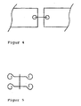
- Haken-Ösen-Prinzip,
- Figur 5:
- miteinander verbundene Haken für die Verbindung durch das Haken-Ösen-Prinzip.
Claims (6)
- Brennstoffzelle, umfassend zwei Elektroden, eine dazwischen liegende Elektrolytschicht und wenigstens eine innere, an eine Elektrode angrenzende Gasverteilerstruktur zur Zu- und Abführung eines Betriebsmittels an bzw. von dieser Elektrode,
dadurch gekennzeichnet, daß die Gasverteilerstruktur sowohl in Betriebsmittelströmung, als auch quer dazu mehrere miteinander in Verbindung stehende modulare Gasverteilereinheiten umfaßt. - Brennstoffzelle nach vorhergehendem Anspruch, wobei die modularen Gasverteilereinheiten lose miteinander in Verbindung stehen.
- Brennstoffzelle nach Anspruch 1 oder 2, dadurch gekennzeichnet, daß eine modulare Gasverteilereinheit als Rohrstück ausgestaltet ist, das eine oder mehrere Öffnungen aufweist, die zur angrenzenden Elektrode führen.
- Brennstoffzelle nach einem der vorhergehenden Ansprüche, dadurch gekennzeichnet, daß modulare Gasverteilereinheiten eine Folie kontaktieren, die den Anodenraum einer Brennstoffzelle vom Kathodenraum einer weiteren Brennstoffzelle gasdicht trennt.
- Brennstoffzelle nach einem der vorhergehenden Ansprüche, dadurch gekennzeichnet, daß eine modulare Gasverteilereinheit aus einem gebogenen Blech besteht.
- Brennstoffzelle nach einem der vorhergehenden Ansprüche, dadurch gekennzeichnet, die Brennstoffzelle eine Hochtemperaturbrennstoffzelle ist.
Applications Claiming Priority (3)
| Application Number | Priority Date | Filing Date | Title |
|---|---|---|---|
| DE19908989A DE19908989C2 (de) | 1999-03-03 | 1999-03-03 | Brennstoffzelle mit modularen, flexiblen Gasverteilerstrukturen |
| DE19908989 | 1999-03-03 | ||
| PCT/EP2000/001700 WO2000052777A1 (de) | 1999-03-03 | 2000-02-29 | Brennstoffzelle mit modularen, flexiblen gasverteilerstrukturen |
Publications (2)
| Publication Number | Publication Date |
|---|---|
| EP1157436A1 EP1157436A1 (de) | 2001-11-28 |
| EP1157436B1 true EP1157436B1 (de) | 2003-11-19 |
Family
ID=7899374
Family Applications (1)
| Application Number | Title | Priority Date | Filing Date |
|---|---|---|---|
| EP00910734A Expired - Lifetime EP1157436B1 (de) | 1999-03-03 | 2000-02-29 | Brennstoffzelle mit modularen, flexiblen gasverteilerstrukturen |
Country Status (6)
| Country | Link |
|---|---|
| US (1) | US20020028369A1 (de) |
| EP (1) | EP1157436B1 (de) |
| AT (1) | ATE254805T1 (de) |
| AU (1) | AU3283800A (de) |
| DE (2) | DE19908989C2 (de) |
| WO (1) | WO2000052777A1 (de) |
Families Citing this family (2)
| Publication number | Priority date | Publication date | Assignee | Title |
|---|---|---|---|---|
| DE10148926A1 (de) * | 2001-10-04 | 2003-04-17 | Forschungszentrum Juelich Gmbh | Verteilerstruktur für Betriebsmittel, Verfahren zu ihrer Herstellung und ihre Verwendung |
| US8410747B2 (en) * | 2004-07-21 | 2013-04-02 | Societe Bic | Flexible fuel cell structures having external support |
Family Cites Families (18)
| Publication number | Priority date | Publication date | Assignee | Title |
|---|---|---|---|---|
| JPS5996669A (ja) * | 1982-11-26 | 1984-06-04 | Agency Of Ind Science & Technol | 溶融炭酸塩型燃料電池 |
| JPS61109262A (ja) * | 1984-11-01 | 1986-05-27 | Hitachi Ltd | 燃料電池 |
| JPS6217959A (ja) * | 1985-07-15 | 1987-01-26 | Fuji Electric Co Ltd | 溶融炭酸塩型燃料電池 |
| JPS62123662A (ja) * | 1985-11-25 | 1987-06-04 | Kureha Chem Ind Co Ltd | 燃料電池用電極基板 |
| JPS6380478A (ja) * | 1986-06-23 | 1988-04-11 | Fuji Electric Co Ltd | 溶融炭酸塩型燃料電池 |
| US5268241A (en) * | 1992-02-20 | 1993-12-07 | Electric Power Research Institute, Inc. | Multiple manifold fuel cell |
| DE4303136C1 (de) * | 1993-02-04 | 1994-06-16 | Mtu Friedrichshafen Gmbh | Verfahren zur Herstellung von Schmelzcarbonat-Brennstoffzellen |
| DE4410711C1 (de) * | 1994-03-28 | 1995-09-07 | Forschungszentrum Juelich Gmbh | Metallische bipolare Platte für HT-Brennstoffzellen und Verfahren zur Herstellung desselben |
| DE4430958C1 (de) * | 1994-08-31 | 1995-10-19 | Forschungszentrum Juelich Gmbh | Feststoffelektrolyt-Hochtemperatur-Brennstoffzelle und Brennstoffzellen-Anordnung |
| DE19519847C1 (de) * | 1995-05-31 | 1997-01-23 | Forschungszentrum Juelich Gmbh | Anodensubstrat für eine Hochtemperatur-Brennstoffzelle |
| DE19531852C1 (de) * | 1995-08-30 | 1996-12-19 | Forschungszentrum Juelich Gmbh | Brennstoffzelle mit Entwässerungssystem |
| US5549983A (en) * | 1996-01-22 | 1996-08-27 | Alliedsignal Inc. | Coflow planar fuel cell stack construction for solid electrolytes |
| DE19636903C1 (de) * | 1996-09-11 | 1998-01-02 | Forschungszentrum Juelich Gmbh | Brennstoffzellenmodul |
| EP0960448B1 (de) * | 1997-02-11 | 2002-04-10 | Fucellco, Incorporated | Brennstoffzellenstapel mit festen elektrolyten und deren anordnung |
| GB9810440D0 (en) * | 1998-05-16 | 1998-07-15 | Secr Defence | Multi element fuel cell system |
| US6361892B1 (en) * | 1999-12-06 | 2002-03-26 | Technology Management, Inc. | Electrochemical apparatus with reactant micro-channels |
| US6423436B1 (en) * | 2000-03-30 | 2002-07-23 | The United States Of America As Represented By The United States Department Of Energy | Tubular electrochemical devices with lateral fuel aperatures for increasing active surface area |
| US6500578B1 (en) * | 2000-04-10 | 2002-12-31 | Hybrid Power Generation Systems, Llc | Stacking and manifolding of angularly offset, unitized solid oxide fuel cells |
-
1999
- 1999-03-03 DE DE19908989A patent/DE19908989C2/de not_active Expired - Fee Related
-
2000
- 2000-02-29 DE DE50004495T patent/DE50004495D1/de not_active Expired - Lifetime
- 2000-02-29 AT AT00910734T patent/ATE254805T1/de active
- 2000-02-29 WO PCT/EP2000/001700 patent/WO2000052777A1/de not_active Ceased
- 2000-02-29 AU AU32838/00A patent/AU3283800A/en not_active Abandoned
- 2000-02-29 EP EP00910734A patent/EP1157436B1/de not_active Expired - Lifetime
-
2001
- 2001-09-01 US US09/945,490 patent/US20020028369A1/en not_active Abandoned
Also Published As
| Publication number | Publication date |
|---|---|
| DE19908989C2 (de) | 2001-07-05 |
| DE50004495D1 (de) | 2003-12-24 |
| DE19908989A1 (de) | 2000-09-07 |
| ATE254805T1 (de) | 2003-12-15 |
| WO2000052777A1 (de) | 2000-09-08 |
| EP1157436A1 (de) | 2001-11-28 |
| US20020028369A1 (en) | 2002-03-07 |
| AU3283800A (en) | 2000-09-21 |
Similar Documents
| Publication | Publication Date | Title |
|---|---|---|
| DE69713337T2 (de) | Festoxidbrennstoffzellengenerator mit auswechselbarem brennstoffzellenstapel von modularem aufbau | |
| DE19681750B4 (de) | Elektrische Verbindungsvorrichtung für eine planare Brennstoffzelle und deren Verwendung | |
| DE2926776C2 (de) | Brennstoff- und/oder Elektrolyse-Zelle | |
| DE4443945C1 (de) | PEM-Brennstoffzelle | |
| US6589681B1 (en) | Series/parallel connection of planar fuel cell stacks | |
| US11888183B2 (en) | Electrolysis or co-electrolysis reactor (SOEC) or fuel cell (SOFC) with electrochemical cell stacking by preassembled modules, and associated production process | |
| DE60313099T2 (de) | Kühlung von Brennstoffzellen | |
| EP1082769B1 (de) | Elektrode mit für ein fluid durchgängigen poren und brennstoffzelle | |
| EP0840947A1 (de) | Hochtemperatur-brennstoffzelle und hochtemperatur-brennstoffzellenstapel mit verbundleiterplatten, die eine kontaktschicht aus chromspinell tragen | |
| DE102006019114A1 (de) | Brennstoffzellenbetriebsverfahren zur verbesserten Wasserstoff- und Sauerstoffverwendung | |
| WO2000031813A1 (de) | Brennstoffzelle mit zuführung eines betriebsmittels über eine gelochte platte | |
| DE112008002508T5 (de) | Brennstoffzellenvorrichtung und elektronisches Gerät, bei dem die Brennstoffzellenvorrichtung eingesetzt wird | |
| DE112004001970T5 (de) | Brennstoffzellenstapel mit einem verbesserten Stromkollektor und verbesserter Isolierung | |
| DE102007022202A1 (de) | Nichtpermeable Beilage mit niedrigem Kontaktwiderstand für Komposit-Brennstoffzellenstapel | |
| EP1157436B1 (de) | Brennstoffzelle mit modularen, flexiblen gasverteilerstrukturen | |
| EP1844513B1 (de) | Interkonnektor für hochtemperaturbrennstoffzellen | |
| WO2013110506A1 (de) | Stack für einen elektrischen energiespeicher | |
| EP1314216B1 (de) | Brennstoffzellenstapel mit internen gasanschlüssen | |
| DE102021112993A1 (de) | Elektrochemischer Reaktionszellenstapel | |
| EP1070362B1 (de) | Bipolare platte mit poröser wand eines brennstoffzellenstapels | |
| DE102018219431A1 (de) | Verbesserter Sekundärinterkonnektor für Brennstoffzellen | |
| EP1665443B1 (de) | Brennstoffzelle und zugehöriges brennstoffzellenmodul | |
| DE112020007094T5 (de) | Wärmeisolierungsstruktur für Hochtemperatur-Reaktionsraum | |
| DE112021002182T5 (de) | Brennstoffzellen-Stromerzeugungssystem | |
| DE10006699B4 (de) | Brennstoffzelle mit Abdichtung für Betriebsstoffe |
Legal Events
| Date | Code | Title | Description |
|---|---|---|---|
| PUAI | Public reference made under article 153(3) epc to a published international application that has entered the european phase |
Free format text: ORIGINAL CODE: 0009012 |
|
| 17P | Request for examination filed |
Effective date: 20010809 |
|
| AK | Designated contracting states |
Kind code of ref document: A1 Designated state(s): AT BE CH CY DE DK ES FI FR GB GR IE IT LI LU MC NL PT SE |
|
| RAP1 | Party data changed (applicant data changed or rights of an application transferred) |
Owner name: FORSCHUNGSZENTRUM JUELICH GMBH |
|
| GRAH | Despatch of communication of intention to grant a patent |
Free format text: ORIGINAL CODE: EPIDOS IGRA |
|
| GRAS | Grant fee paid |
Free format text: ORIGINAL CODE: EPIDOSNIGR3 |
|
| GRAA | (expected) grant |
Free format text: ORIGINAL CODE: 0009210 |
|
| AK | Designated contracting states |
Kind code of ref document: B1 Designated state(s): AT BE CH CY DE DK ES FI FR GB GR IE IT LI LU MC NL PT SE |
|
| PG25 | Lapsed in a contracting state [announced via postgrant information from national office to epo] |
Ref country code: IT Free format text: LAPSE BECAUSE OF FAILURE TO SUBMIT A TRANSLATION OF THE DESCRIPTION OR TO PAY THE FEE WITHIN THE PRE;WARNING: LAPSES OF ITALIAN PATENTS WITH EFFECTIVE DATE BEFORE 2007 MAY HAVE OCCURRED AT ANY TIME BEFORE 2007. THE CORRECT EFFECTIVE DATE MAY BE DIFFERENT FROM THE ONE RECORDED.SCRIBED TIME-LIMIT Effective date: 20031119 Ref country code: NL Free format text: LAPSE BECAUSE OF FAILURE TO SUBMIT A TRANSLATION OF THE DESCRIPTION OR TO PAY THE FEE WITHIN THE PRESCRIBED TIME-LIMIT Effective date: 20031119 Ref country code: ES Free format text: LAPSE BECAUSE OF FAILURE TO SUBMIT A TRANSLATION OF THE DESCRIPTION OR TO PAY THE FEE WITHIN THE PRESCRIBED TIME-LIMIT Effective date: 20031119 Ref country code: CY Free format text: LAPSE BECAUSE OF FAILURE TO SUBMIT A TRANSLATION OF THE DESCRIPTION OR TO PAY THE FEE WITHIN THE PRESCRIBED TIME-LIMIT Effective date: 20031119 Ref country code: FI Free format text: LAPSE BECAUSE OF FAILURE TO SUBMIT A TRANSLATION OF THE DESCRIPTION OR TO PAY THE FEE WITHIN THE PRESCRIBED TIME-LIMIT Effective date: 20031119 |
|
| REG | Reference to a national code |
Ref country code: GB Ref legal event code: FG4D Free format text: NOT ENGLISH |
|
| REG | Reference to a national code |
Ref country code: CH Ref legal event code: EP |
|
| REF | Corresponds to: |
Ref document number: 50004495 Country of ref document: DE Date of ref document: 20031224 Kind code of ref document: P |
|
| REG | Reference to a national code |
Ref country code: IE Ref legal event code: FG4D Free format text: GERMAN |
|
| PG25 | Lapsed in a contracting state [announced via postgrant information from national office to epo] |
Ref country code: SE Free format text: LAPSE BECAUSE OF FAILURE TO SUBMIT A TRANSLATION OF THE DESCRIPTION OR TO PAY THE FEE WITHIN THE PRESCRIBED TIME-LIMIT Effective date: 20040219 Ref country code: DK Free format text: LAPSE BECAUSE OF FAILURE TO SUBMIT A TRANSLATION OF THE DESCRIPTION OR TO PAY THE FEE WITHIN THE PRESCRIBED TIME-LIMIT Effective date: 20040219 Ref country code: GR Free format text: LAPSE BECAUSE OF FAILURE TO SUBMIT A TRANSLATION OF THE DESCRIPTION OR TO PAY THE FEE WITHIN THE PRESCRIBED TIME-LIMIT Effective date: 20040219 |
|
| GBT | Gb: translation of ep patent filed (gb section 77(6)(a)/1977) |
Effective date: 20040218 |
|
| NLV1 | Nl: lapsed or annulled due to failure to fulfill the requirements of art. 29p and 29m of the patents act | ||
| ET | Fr: translation filed | ||
| PLBE | No opposition filed within time limit |
Free format text: ORIGINAL CODE: 0009261 |
|
| STAA | Information on the status of an ep patent application or granted ep patent |
Free format text: STATUS: NO OPPOSITION FILED WITHIN TIME LIMIT |
|
| 26N | No opposition filed |
Effective date: 20040820 |
|
| PG25 | Lapsed in a contracting state [announced via postgrant information from national office to epo] |
Ref country code: PT Free format text: LAPSE BECAUSE OF NON-PAYMENT OF DUE FEES Effective date: 20040419 |
|
| PGFP | Annual fee paid to national office [announced via postgrant information from national office to epo] |
Ref country code: MC Payment date: 20110217 Year of fee payment: 12 Ref country code: IE Payment date: 20110216 Year of fee payment: 12 |
|
| PGFP | Annual fee paid to national office [announced via postgrant information from national office to epo] |
Ref country code: DE Payment date: 20110115 Year of fee payment: 12 Ref country code: CH Payment date: 20110222 Year of fee payment: 12 Ref country code: AT Payment date: 20110217 Year of fee payment: 12 Ref country code: LU Payment date: 20110222 Year of fee payment: 12 Ref country code: FR Payment date: 20110301 Year of fee payment: 12 |
|
| PGFP | Annual fee paid to national office [announced via postgrant information from national office to epo] |
Ref country code: GB Payment date: 20110221 Year of fee payment: 12 Ref country code: BE Payment date: 20110221 Year of fee payment: 12 |
|
| BERE | Be: lapsed |
Owner name: FORSCHUNGSZENTRUM *JULICH G.M.B.H. Effective date: 20120228 |
|
| PG25 | Lapsed in a contracting state [announced via postgrant information from national office to epo] |
Ref country code: MC Free format text: LAPSE BECAUSE OF NON-PAYMENT OF DUE FEES Effective date: 20120229 |
|
| REG | Reference to a national code |
Ref country code: CH Ref legal event code: PL |
|
| GBPC | Gb: european patent ceased through non-payment of renewal fee |
Effective date: 20120229 |
|
| PG25 | Lapsed in a contracting state [announced via postgrant information from national office to epo] |
Ref country code: CH Free format text: LAPSE BECAUSE OF NON-PAYMENT OF DUE FEES Effective date: 20120229 Ref country code: LI Free format text: LAPSE BECAUSE OF NON-PAYMENT OF DUE FEES Effective date: 20120229 |
|
| REG | Reference to a national code |
Ref country code: IE Ref legal event code: MM4A |
|
| REG | Reference to a national code |
Ref country code: FR Ref legal event code: ST Effective date: 20121031 |
|
| REG | Reference to a national code |
Ref country code: AT Ref legal event code: MM01 Ref document number: 254805 Country of ref document: AT Kind code of ref document: T Effective date: 20120229 |
|
| REG | Reference to a national code |
Ref country code: DE Ref legal event code: R119 Ref document number: 50004495 Country of ref document: DE Effective date: 20120901 |
|
| PG25 | Lapsed in a contracting state [announced via postgrant information from national office to epo] |
Ref country code: BE Free format text: LAPSE BECAUSE OF NON-PAYMENT OF DUE FEES Effective date: 20120228 |
|
| PG25 | Lapsed in a contracting state [announced via postgrant information from national office to epo] |
Ref country code: FR Free format text: LAPSE BECAUSE OF NON-PAYMENT OF DUE FEES Effective date: 20120229 Ref country code: IE Free format text: LAPSE BECAUSE OF NON-PAYMENT OF DUE FEES Effective date: 20120229 Ref country code: GB Free format text: LAPSE BECAUSE OF NON-PAYMENT OF DUE FEES Effective date: 20120229 Ref country code: AT Free format text: LAPSE BECAUSE OF NON-PAYMENT OF DUE FEES Effective date: 20120229 |
|
| PG25 | Lapsed in a contracting state [announced via postgrant information from national office to epo] |
Ref country code: DE Free format text: LAPSE BECAUSE OF NON-PAYMENT OF DUE FEES Effective date: 20120901 |
|
| PG25 | Lapsed in a contracting state [announced via postgrant information from national office to epo] |
Ref country code: LU Free format text: LAPSE BECAUSE OF NON-PAYMENT OF DUE FEES Effective date: 20120229 |