EP1157320B1 - Procede permettant de generer une tension continue regulee a partir d'une tension alternative, et dispositif d'alimentation en courant pour la mise en oeuvre de ce procede - Google Patents
Procede permettant de generer une tension continue regulee a partir d'une tension alternative, et dispositif d'alimentation en courant pour la mise en oeuvre de ce procede Download PDFInfo
- Publication number
- EP1157320B1 EP1157320B1 EP00903561A EP00903561A EP1157320B1 EP 1157320 B1 EP1157320 B1 EP 1157320B1 EP 00903561 A EP00903561 A EP 00903561A EP 00903561 A EP00903561 A EP 00903561A EP 1157320 B1 EP1157320 B1 EP 1157320B1
- Authority
- EP
- European Patent Office
- Prior art keywords
- limit value
- power supply
- supply device
- conversion mode
- switching
- Prior art date
- Legal status (The legal status is an assumption and is not a legal conclusion. Google has not performed a legal analysis and makes no representation as to the accuracy of the status listed.)
- Expired - Lifetime
Links
Images

Classifications
-
- H—ELECTRICITY
- H02—GENERATION; CONVERSION OR DISTRIBUTION OF ELECTRIC POWER
- H02M—APPARATUS FOR CONVERSION BETWEEN AC AND AC, BETWEEN AC AND DC, OR BETWEEN DC AND DC, AND FOR USE WITH MAINS OR SIMILAR POWER SUPPLY SYSTEMS; CONVERSION OF DC OR AC INPUT POWER INTO SURGE OUTPUT POWER; CONTROL OR REGULATION THEREOF
- H02M3/00—Conversion of dc power input into dc power output
- H02M3/02—Conversion of dc power input into dc power output without intermediate conversion into ac
- H02M3/04—Conversion of dc power input into dc power output without intermediate conversion into ac by static converters
- H02M3/10—Conversion of dc power input into dc power output without intermediate conversion into ac by static converters using discharge tubes with control electrode or semiconductor devices with control electrode
- H02M3/145—Conversion of dc power input into dc power output without intermediate conversion into ac by static converters using discharge tubes with control electrode or semiconductor devices with control electrode using devices of a triode or transistor type requiring continuous application of a control signal
- H02M3/155—Conversion of dc power input into dc power output without intermediate conversion into ac by static converters using discharge tubes with control electrode or semiconductor devices with control electrode using devices of a triode or transistor type requiring continuous application of a control signal using semiconductor devices only
- H02M3/156—Conversion of dc power input into dc power output without intermediate conversion into ac by static converters using discharge tubes with control electrode or semiconductor devices with control electrode using devices of a triode or transistor type requiring continuous application of a control signal using semiconductor devices only with automatic control of output voltage or current, e.g. switching regulators
- H02M3/158—Conversion of dc power input into dc power output without intermediate conversion into ac by static converters using discharge tubes with control electrode or semiconductor devices with control electrode using devices of a triode or transistor type requiring continuous application of a control signal using semiconductor devices only with automatic control of output voltage or current, e.g. switching regulators including plural semiconductor devices as final control devices for a single load
-
- H—ELECTRICITY
- H02—GENERATION; CONVERSION OR DISTRIBUTION OF ELECTRIC POWER
- H02M—APPARATUS FOR CONVERSION BETWEEN AC AND AC, BETWEEN AC AND DC, OR BETWEEN DC AND DC, AND FOR USE WITH MAINS OR SIMILAR POWER SUPPLY SYSTEMS; CONVERSION OF DC OR AC INPUT POWER INTO SURGE OUTPUT POWER; CONTROL OR REGULATION THEREOF
- H02M1/00—Details of apparatus for conversion
- H02M1/0067—Converter structures employing plural converter units, other than for parallel operation of the units on a single load
- H02M1/007—Plural converter units in cascade
Landscapes
- Engineering & Computer Science (AREA)
- Power Engineering (AREA)
- Rectifiers (AREA)
- Dc-Dc Converters (AREA)
- Electrical Discharge Machining, Electrochemical Machining, And Combined Machining (AREA)
- Inverter Devices (AREA)
- Control Of Electrical Variables (AREA)
- Generation Of Surge Voltage And Current (AREA)
Claims (7)
- Procédé pour générer une tension continue réglée (UG) à partir d'une tension alternative (UW) au moyen d'un dispositif d'alimentation en courant, qui comporte un convertisseur abaisseur (S1, D1, D2, C0, L) comportant un premier interrupteur (S1), un convertisseur élévateur (S2, D2, C0, L) comportant un second interrupteur (S2), une bobine d'arrêt (L) commune aux convertisseurs et un dispositif de commande (11), qui commande séquentiellement le convertisseur abaisseur et le convertisseur élévateur de telle sorte que le dispositif d'alimentation en courant fonctionne respectivement dans un mode de conversion avec abaissement et dans un mode de conversion avec élévation, caractérisé en ceen ce qu'un signal (I) de mesure du courant (IL), qui circule dans la bobine d'arrêt (L), est comparé à une première valeur limite (A), à une seconde valeur limite (R), à une troisième valeur limite (C), la première valeur limite (A) étant presque nulle et la seconde valeur limite (B) étant située entre la première valeur limite (A) et la troisième valeur limite (C), et au moins les seconde et troisième valeurs (B, C) étant inversement proportionnelles aux grandeurs physiques qui correspondent à la valeur réelle (X) de la tension continue (UG),en ce que le dispositif de commande (11) commute le dispositif d'alimentation en courant du mode de conversion avec élévation au mode de conversion avec abaissement,. lorsque le signal (I) de mesure du courant, qui augmente, diminue une fois qu'est atteinte la seconde valeur limite (B), et n'atteint pas à nouveau la première valeur limite (A), mais augmente (t4) jusqu'à la troisième valeur limite (C),en ce que le dispositif de commande (11) commute le dispositif d'alimentation en courant du mode de conversion avec abaissement au mode de conversion avec élévation, lorsque le signal de mesure de courant, qui diminue, augmente après avoir atteint la première valeur limite (A) et n'atteint pas la seconde valeur limite (B), mais retombe à nouveau (t6) à la première valeur limite (A), eten ce que le premier interrupteur (S1) est fermé dans le mode de conversion avec élévation (t0-t1) et pendant ce temps le second interrupteur (S2) est ouvert lorsque le signal de mesure de courant (I), qui augmente, atteint la valeur limite (B), et est fermé lorsque le signal de mesure de courant (I), qui diminue, atteint la première valeur limite (A) , et que dans le mode de conversion avec abaissement (t1-t5), le second interrupteur (S2) est ouvert et, pendant ce temps, le premier interrupteur (S1) est fermé, lorsque le signal de mesure de courant (I), qui diminue, atteint la première valeur limite (A), et est ouvert, lorsque le signal de mesure de courant (I), qui augmente, atteint la troisième valeur limite (C).
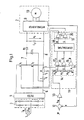
- Dispositif d'alimentation en courant pour un appareil d'utilisation (2), dans lequel le dispositif d'alimentation en courant contient un convertisseur élévateur (S2, D2, C0, L) et un convertisseur abaisseur (S1, D1, D2, C0, L), qui partagent la bobine d'arrêt commune (T), et dans lequel un dispositif de commande (11) fait fonctionner le dispositif d'alimentation en courant alternativement dans un mode de conversion avec abaissement et dans un mode de conversion avec élévation,
caractérisé en ce que dans le dispositif de commande (11) sont produites au moins deux valeurs limites (B, C), qui varient lorsqu'une tension de sortie (UG) du dispositif d'alimentation en courant varie,en ce que ces valeurs limites sont comparées au moyen de comparateurs (15, 16, 17) à un signal de mesure de courant (I), qui correspond au courant de bobine (IL), et qu'un signal de sortie (D, E, F) du comparateur est formé en conséquence,en ce que ce signal de sortie est envoyé à un circuit logique (18) et en conséquence une détermination est faite pour savoir quand la commutation doit être exécutée du mode de conversion avec élévation au mode de conversion avec abaissement où inversement, eten ce que le signal de sortie est utilisé à l'aide du circuit logique pour commander de façon cadencée des interrupteurs (S1, S2), pendant le mode de conversion avec abaissement ou pendant le mode de conversion avec élévation. - Dispositif d'alimentation en courant selon la revendication 2, caractérisé en ce que le dispositif de commande (11) comporte un comparateur (15, 16, 17) pour la comparaison respectivement de l'une des valeurs limites (A, B, C) au signal de mesure de courant (I) d'un dispositif de mesure de courant (5) disposé en série avec la bobine d'arrêt (T), et en ce qu'au moins les seconde et troisième valeurs limites (B, C) dépendent du signal de sortie (XW) du circuit de sommation (12).
- Dispositif d'alimentation en courant selon la revendication 3, caractérisé en ce que les seconde et troisième valeurs limites (B, C) sont directement proportionnelles au signal de sortie (XW) du circuit de sommation (12).
- Dispositif d'alimentation en courant selon la revendication 4, caractérisé en ce que les valeurs limites (A, B, C) sont prélevées au niveau d'un diviseur de tension (14), qui est relié à la sortie du circuit de sommation (12) par l'intermédiaire d'un amplificateur (13).
- Dispositif d'alimentation en courant selon l'une des revendications 3 à 5, caractérisé en ce que les interrupteurs (S1, S2) sont branchés directement en série.
- Dispositif d'alimentation en courant selon l'une des revendications 3 à 6, caractérisé en ce que le dispositif de commande (11) comporte un limiteur de la fréquence de commutation, qui empêche un dépassement par valeurs inférieures d'une durée de période de commutation minimale des interrupteurs (S1, S2) par retardement de l'instant de fermeture des interrupteurs (S1, S2) lorsqu'à partir du dernier instant de fermeture, une durée minimale ne s'est pas écoulée, et empêche un dépassement par valeur supérieures d'une durée de période de commutation maximale par avance de l'instant de fermeture des interrupteurs (S1, S2), lorsqu'une durée maximale s'est écoulée depuis le dernier instant de fermeture.
Applications Claiming Priority (3)
| Application Number | Priority Date | Filing Date | Title |
|---|---|---|---|
| DE19909464 | 1999-03-04 | ||
| DE19909464A DE19909464C2 (de) | 1999-03-04 | 1999-03-04 | Verfahren zur Erzeugung einer geregelten Gleichspannung aus einer Wechselspannung und Stromversorgungseinrichtung zur Durchführung des Verfahrens |
| PCT/DK2000/000058 WO2000052548A1 (fr) | 1999-03-04 | 2000-02-14 | Procede permettant de generer une tension continue regulee a partir d'une tension alternative, et dispositif d'alimentation en courant pour la mise en oeuvre de ce procede |
Publications (2)
| Publication Number | Publication Date |
|---|---|
| EP1157320A1 EP1157320A1 (fr) | 2001-11-28 |
| EP1157320B1 true EP1157320B1 (fr) | 2003-05-07 |
Family
ID=7899662
Family Applications (1)
| Application Number | Title | Priority Date | Filing Date |
|---|---|---|---|
| EP00903561A Expired - Lifetime EP1157320B1 (fr) | 1999-03-04 | 2000-02-14 | Procede permettant de generer une tension continue regulee a partir d'une tension alternative, et dispositif d'alimentation en courant pour la mise en oeuvre de ce procede |
Country Status (7)
| Country | Link |
|---|---|
| US (1) | US6483278B2 (fr) |
| EP (1) | EP1157320B1 (fr) |
| AT (1) | ATE239934T1 (fr) |
| AU (1) | AU2536000A (fr) |
| BR (1) | BR0008698A (fr) |
| DE (2) | DE19909464C2 (fr) |
| WO (1) | WO2000052548A1 (fr) |
Families Citing this family (24)
| Publication number | Priority date | Publication date | Assignee | Title |
|---|---|---|---|---|
| US9397370B2 (en) * | 1999-06-25 | 2016-07-19 | The Board Of Trustees Of The University Of Illinois | Single and multiple cell battery with built-in controller |
| AU2001249226A1 (en) * | 2000-03-22 | 2001-10-03 | The Board Of Trustees Of The University Of Illinois | Oscillatorless dc-dc power converter |
| US8337166B2 (en) | 2001-11-26 | 2012-12-25 | Shurflo, Llc | Pump and pump control circuit apparatus and method |
| EP1524571B1 (fr) * | 2002-07-10 | 2011-04-20 | Marvell World Trade Ltd. | Système de commande pour un régulateur de sortie |
| US6977492B2 (en) * | 2002-07-10 | 2005-12-20 | Marvell World Trade Ltd. | Output regulator |
| US8540493B2 (en) | 2003-12-08 | 2013-09-24 | Sta-Rite Industries, Llc | Pump control system and method |
| US9257895B2 (en) * | 2004-06-17 | 2016-02-09 | Grant A. MacLennan | Distributed gap inductor filter apparatus and method of use thereof |
| US8043070B2 (en) | 2004-08-26 | 2011-10-25 | Pentair Water Pool And Spa, Inc. | Speed control |
| US7845913B2 (en) | 2004-08-26 | 2010-12-07 | Pentair Water Pool And Spa, Inc. | Flow control |
| US8469675B2 (en) | 2004-08-26 | 2013-06-25 | Pentair Water Pool And Spa, Inc. | Priming protection |
| US8019479B2 (en) | 2004-08-26 | 2011-09-13 | Pentair Water Pool And Spa, Inc. | Control algorithm of variable speed pumping system |
| US8480373B2 (en) | 2004-08-26 | 2013-07-09 | Pentair Water Pool And Spa, Inc. | Filter loading |
| US8602745B2 (en) | 2004-08-26 | 2013-12-10 | Pentair Water Pool And Spa, Inc. | Anti-entrapment and anti-dead head function |
| US7874808B2 (en) | 2004-08-26 | 2011-01-25 | Pentair Water Pool And Spa, Inc. | Variable speed pumping system and method |
| US7686589B2 (en) | 2004-08-26 | 2010-03-30 | Pentair Water Pool And Spa, Inc. | Pumping system with power optimization |
| EP2137802B1 (fr) * | 2007-04-19 | 2014-12-31 | QUALCOMM Incorporated | Systèmes de chargement de batterie et procédés avec limite de courant réglable |
| DE102007037557B4 (de) | 2007-08-09 | 2014-05-15 | Werner Turck Gmbh & Co. Kg | Auf- / Abwärtswandler mit unterdrückbarer Aufwärtswandelfunktion |
| MX2011003708A (es) | 2008-10-06 | 2011-06-16 | Pentair Water Pool & Spa Inc | Metodo para operar un sistema de seguridad para alivio de vacio. |
| US8436559B2 (en) | 2009-06-09 | 2013-05-07 | Sta-Rite Industries, Llc | System and method for motor drive control pad and drive terminals |
| US8564233B2 (en) | 2009-06-09 | 2013-10-22 | Sta-Rite Industries, Llc | Safety system and method for pump and motor |
| US9556874B2 (en) | 2009-06-09 | 2017-01-31 | Pentair Flow Technologies, Llc | Method of controlling a pump and motor |
| SG191067A1 (en) | 2010-12-08 | 2013-08-30 | Pentair Water Pool & Spa Inc | Discharge vacuum relief valve for safety vacuum release system |
| BR112014010665A2 (pt) | 2011-11-01 | 2017-12-05 | Pentair Water Pool & Spa Inc | sistema e processo de bloqueio de vazão |
| US9885360B2 (en) | 2012-10-25 | 2018-02-06 | Pentair Flow Technologies, Llc | Battery backup sump pump systems and methods |
Family Cites Families (6)
| Publication number | Priority date | Publication date | Assignee | Title |
|---|---|---|---|---|
| DE3608082A1 (de) * | 1986-03-07 | 1987-09-10 | Licentia Gmbh | Schaltungsanordnung zur konstanthaltung der ausgangsgleichspannung bei wechselnder eingangsgleichspannung einer tiefsetz-hochsetzstellerkombination |
| SE8605266L (sv) * | 1986-12-09 | 1988-06-10 | Ragnar Jonsson | Switch-koppling |
| US4943762A (en) * | 1988-01-27 | 1990-07-24 | Codar Technology, Inc. | Power supply system |
| US4964029A (en) * | 1988-05-18 | 1990-10-16 | Viteq Corporation | AC to DC power converter with input current waveform control for buck-boost regulation of output |
| US5235504A (en) * | 1991-03-15 | 1993-08-10 | Emerson Electric Co. | High power-factor converter for motor drives and power supplies |
| US5602463A (en) * | 1995-12-11 | 1997-02-11 | Lockheed Martin Corporation | DC power supply with enhanced input power factor using a buck and boost converter |
-
1999
- 1999-03-04 DE DE19909464A patent/DE19909464C2/de not_active Expired - Fee Related
-
2000
- 2000-02-14 WO PCT/DK2000/000058 patent/WO2000052548A1/fr active IP Right Grant
- 2000-02-14 AT AT00903561T patent/ATE239934T1/de not_active IP Right Cessation
- 2000-02-14 DE DE50002074T patent/DE50002074D1/de not_active Expired - Lifetime
- 2000-02-14 BR BR0008698-3A patent/BR0008698A/pt not_active IP Right Cessation
- 2000-02-14 EP EP00903561A patent/EP1157320B1/fr not_active Expired - Lifetime
- 2000-02-14 AU AU25360/00A patent/AU2536000A/en not_active Abandoned
-
2001
- 2001-08-30 US US09/943,256 patent/US6483278B2/en not_active Expired - Lifetime
Also Published As
| Publication number | Publication date |
|---|---|
| DE19909464A1 (de) | 2000-09-07 |
| EP1157320A1 (fr) | 2001-11-28 |
| WO2000052548A1 (fr) | 2000-09-08 |
| US20020031001A1 (en) | 2002-03-14 |
| DE19909464C2 (de) | 2001-03-22 |
| ATE239934T1 (de) | 2003-05-15 |
| DE50002074D1 (de) | 2003-06-12 |
| AU2536000A (en) | 2000-09-21 |
| US6483278B2 (en) | 2002-11-19 |
| BR0008698A (pt) | 2001-12-26 |
Similar Documents
| Publication | Publication Date | Title |
|---|---|---|
| EP1157320B1 (fr) | Procede permettant de generer une tension continue regulee a partir d'une tension alternative, et dispositif d'alimentation en courant pour la mise en oeuvre de ce procede | |
| DE19710319B4 (de) | Schaltung zum Sperren einer Halbleiterschaltvorrichtung bei Überstrom | |
| DE19545154C2 (de) | Stromversorgungseinrichtung | |
| DE19814681B4 (de) | Current-Mode-Schaltregler | |
| DE4206263C2 (de) | Steuersatz für pulsbreitenmodulierten Dreipunktwechselrichter | |
| AT403865B (de) | Spannungsumsetzungsvorrichtung für einen gleichspannungsverbraucher | |
| EP1146630B1 (fr) | Procédé de regulation du courant de sortie et/ou tension de sortie d'un circuit d'alimentation à decoupage | |
| EP1316138B1 (fr) | Regulateur de commutation a mode courant | |
| DE112009004627T5 (de) | Leistungsumwandlungsvorrichtung | |
| EP2709257A2 (fr) | Circuit de convertisseur de courant et procédé de commande du circuit de convertisseur de courant | |
| EP0178446A1 (fr) | Dispositif de hacheur à semi-conducteur | |
| DE112017005404T5 (de) | DC-DC Wandler | |
| DE10242218B3 (de) | Verfahren zur Ansteuerung eines Schalters in einem freischwingenden Schaltnetzteil und Ansteuerschaltung für einen Schalter in einem freischwingenden Schaltnetzteil | |
| DE60101694T2 (de) | Rückkopplungsschleife für Leistungsumwandler | |
| DE102017212462A1 (de) | Galvanisch gekoppelter elektrischer Wandler | |
| DE10339025A1 (de) | Stromversorgungssystem | |
| EP1647087B1 (fr) | Dispositif de commande servant a commander un commutateur de charge dans un regulateur a decoupage et procede pour commander un commutateur de charge | |
| DE10221450A1 (de) | Schaltungsanordnung für einen resonanten Konverter und Verfahren zu dessen Betrieb | |
| DE4008652A1 (de) | Netzteil mit gleichstrom-gleichstrom-wandler | |
| EP2985896A1 (fr) | Systeme d'accentuation du facteur de puissance cote reseau de moteurs ec triphases | |
| EP3595155A1 (fr) | Unité de commande pour produire une puissance variable de sortie d'un circuit en pont commutant résonant | |
| CH688066A5 (de) | Wechselstrom/Gleichstrom-Wandler nach dem Buck-/Boost-Prinzip. | |
| EP0243948B1 (fr) | Circuit de contrôle pour une lampe à arc | |
| EP0978933A2 (fr) | Convertisseur courant continu - courant continu | |
| DE102007035606B4 (de) | Verfahren zur Ansteuerung und Ansteuerschaltung für einen Schalter einer Leistungsfaktorkorrekturschaltung |
Legal Events
| Date | Code | Title | Description |
|---|---|---|---|
| PUAI | Public reference made under article 153(3) epc to a published international application that has entered the european phase |
Free format text: ORIGINAL CODE: 0009012 |
|
| 17P | Request for examination filed |
Effective date: 20010815 |
|
| AK | Designated contracting states |
Kind code of ref document: A1 Designated state(s): AT BE CH CY DE DK ES FI FR GB GR IE IT LI LU MC NL PT SE |
|
| 17Q | First examination report despatched |
Effective date: 20020124 |
|
| GRAG | Despatch of communication of intention to grant |
Free format text: ORIGINAL CODE: EPIDOS AGRA |
|
| GRAG | Despatch of communication of intention to grant |
Free format text: ORIGINAL CODE: EPIDOS AGRA |
|
| GRAG | Despatch of communication of intention to grant |
Free format text: ORIGINAL CODE: EPIDOS AGRA |
|
| GRAH | Despatch of communication of intention to grant a patent |
Free format text: ORIGINAL CODE: EPIDOS IGRA |
|
| GRAH | Despatch of communication of intention to grant a patent |
Free format text: ORIGINAL CODE: EPIDOS IGRA |
|
| GRAA | (expected) grant |
Free format text: ORIGINAL CODE: 0009210 |
|
| AK | Designated contracting states |
Designated state(s): AT BE CH CY DE DK ES FI FR GB GR IE IT LI LU MC NL PT SE |
|
| PG25 | Lapsed in a contracting state [announced via postgrant information from national office to epo] |
Ref country code: GB Free format text: LAPSE BECAUSE OF FAILURE TO SUBMIT A TRANSLATION OF THE DESCRIPTION OR TO PAY THE FEE WITHIN THE PRESCRIBED TIME-LIMIT Effective date: 20030507 Ref country code: FI Free format text: LAPSE BECAUSE OF FAILURE TO SUBMIT A TRANSLATION OF THE DESCRIPTION OR TO PAY THE FEE WITHIN THE PRESCRIBED TIME-LIMIT Effective date: 20030507 Ref country code: NL Free format text: LAPSE BECAUSE OF FAILURE TO SUBMIT A TRANSLATION OF THE DESCRIPTION OR TO PAY THE FEE WITHIN THE PRESCRIBED TIME-LIMIT Effective date: 20030507 Ref country code: CY Free format text: LAPSE BECAUSE OF FAILURE TO SUBMIT A TRANSLATION OF THE DESCRIPTION OR TO PAY THE FEE WITHIN THE PRESCRIBED TIME-LIMIT Effective date: 20030507 Ref country code: IE Free format text: LAPSE BECAUSE OF NON-PAYMENT OF DUE FEES Effective date: 20030507 |
|
| REG | Reference to a national code |
Ref country code: GB Ref legal event code: FG4D Free format text: NOT ENGLISH |
|
| REG | Reference to a national code |
Ref country code: CH Ref legal event code: EP |
|
| REG | Reference to a national code |
Ref country code: IE Ref legal event code: FG4D Free format text: GERMAN |
|
| REF | Corresponds to: |
Ref document number: 50002074 Country of ref document: DE Date of ref document: 20030612 Kind code of ref document: P |
|
| PG25 | Lapsed in a contracting state [announced via postgrant information from national office to epo] |
Ref country code: PT Free format text: LAPSE BECAUSE OF FAILURE TO SUBMIT A TRANSLATION OF THE DESCRIPTION OR TO PAY THE FEE WITHIN THE PRESCRIBED TIME-LIMIT Effective date: 20030807 Ref country code: SE Free format text: LAPSE BECAUSE OF FAILURE TO SUBMIT A TRANSLATION OF THE DESCRIPTION OR TO PAY THE FEE WITHIN THE PRESCRIBED TIME-LIMIT Effective date: 20030807 Ref country code: DK Free format text: LAPSE BECAUSE OF FAILURE TO SUBMIT A TRANSLATION OF THE DESCRIPTION OR TO PAY THE FEE WITHIN THE PRESCRIBED TIME-LIMIT Effective date: 20030807 Ref country code: GR Free format text: LAPSE BECAUSE OF FAILURE TO SUBMIT A TRANSLATION OF THE DESCRIPTION OR TO PAY THE FEE WITHIN THE PRESCRIBED TIME-LIMIT Effective date: 20030807 |
|
| PG25 | Lapsed in a contracting state [announced via postgrant information from national office to epo] |
Ref country code: ES Free format text: LAPSE BECAUSE OF FAILURE TO SUBMIT A TRANSLATION OF THE DESCRIPTION OR TO PAY THE FEE WITHIN THE PRESCRIBED TIME-LIMIT Effective date: 20030818 |
|
| NLV1 | Nl: lapsed or annulled due to failure to fulfill the requirements of art. 29p and 29m of the patents act | ||
| GBV | Gb: ep patent (uk) treated as always having been void in accordance with gb section 77(7)/1977 [no translation filed] |
Effective date: 20030507 |
|
| REG | Reference to a national code |
Ref country code: IE Ref legal event code: FD4D Ref document number: 1157320E Country of ref document: IE |
|
| ET | Fr: translation filed | ||
| PG25 | Lapsed in a contracting state [announced via postgrant information from national office to epo] |
Ref country code: AT Free format text: LAPSE BECAUSE OF NON-PAYMENT OF DUE FEES Effective date: 20040214 Ref country code: LU Free format text: LAPSE BECAUSE OF NON-PAYMENT OF DUE FEES Effective date: 20040214 |
|
| PGFP | Annual fee paid to national office [announced via postgrant information from national office to epo] |
Ref country code: FR Payment date: 20040218 Year of fee payment: 5 |
|
| PG25 | Lapsed in a contracting state [announced via postgrant information from national office to epo] |
Ref country code: BE Free format text: LAPSE BECAUSE OF NON-PAYMENT OF DUE FEES Effective date: 20040228 Ref country code: MC Free format text: LAPSE BECAUSE OF NON-PAYMENT OF DUE FEES Effective date: 20040228 |
|
| PG25 | Lapsed in a contracting state [announced via postgrant information from national office to epo] |
Ref country code: CH Free format text: LAPSE BECAUSE OF NON-PAYMENT OF DUE FEES Effective date: 20040229 Ref country code: LI Free format text: LAPSE BECAUSE OF NON-PAYMENT OF DUE FEES Effective date: 20040229 |
|
| PLBE | No opposition filed within time limit |
Free format text: ORIGINAL CODE: 0009261 |
|
| STAA | Information on the status of an ep patent application or granted ep patent |
Free format text: STATUS: NO OPPOSITION FILED WITHIN TIME LIMIT |
|
| 26N | No opposition filed |
Effective date: 20040210 |
|
| BERE | Be: lapsed |
Owner name: *DANFOSS COMPRESSORS G.M.B.H. Effective date: 20040228 |
|
| REG | Reference to a national code |
Ref country code: CH Ref legal event code: PL |
|
| PG25 | Lapsed in a contracting state [announced via postgrant information from national office to epo] |
Ref country code: FR Free format text: LAPSE BECAUSE OF NON-PAYMENT OF DUE FEES Effective date: 20050228 |
|
| PGFP | Annual fee paid to national office [announced via postgrant information from national office to epo] |
Ref country code: IT Payment date: 20090213 Year of fee payment: 10 |
|
| PG25 | Lapsed in a contracting state [announced via postgrant information from national office to epo] |
Ref country code: IT Free format text: LAPSE BECAUSE OF NON-PAYMENT OF DUE FEES Effective date: 20100214 |
|
| REG | Reference to a national code |
Ref country code: DE Ref legal event code: R081 Ref document number: 50002074 Country of ref document: DE Owner name: SECOP GMBH, DE Free format text: FORMER OWNER: DANFOSS COMPRESSORS GMBH, 24939 FLENSBURG, DE Effective date: 20110310 |
|
| REG | Reference to a national code |
Ref country code: FR Ref legal event code: ST Effective date: 20111021 |
|
| REG | Reference to a national code |
Ref country code: DE Ref legal event code: R082 Ref document number: 50002074 Country of ref document: DE Representative=s name: PATENTANWAELTE KNOBLAUCH UND KNOBLAUCH, DE Effective date: 20120209 Ref country code: DE Ref legal event code: R081 Ref document number: 50002074 Country of ref document: DE Owner name: SECOP GMBH, DE Free format text: FORMER OWNER: DANFOSS FLENSBURG GMBH, 24939 FLENSBURG, DE Effective date: 20120209 |
|
| PGFP | Annual fee paid to national office [announced via postgrant information from national office to epo] |
Ref country code: DE Payment date: 20180430 Year of fee payment: 19 |
|
| REG | Reference to a national code |
Ref country code: DE Ref legal event code: R082 Ref document number: 50002074 Country of ref document: DE Representative=s name: KEIL & SCHAAFHAUSEN PATENT- UND RECHTSANWAELTE, DE |
|
| REG | Reference to a national code |
Ref country code: DE Ref legal event code: R119 Ref document number: 50002074 Country of ref document: DE |
|
| PG25 | Lapsed in a contracting state [announced via postgrant information from national office to epo] |
Ref country code: DE Free format text: LAPSE BECAUSE OF NON-PAYMENT OF DUE FEES Effective date: 20190903 |