EP1157256B1 - Längenmesssystem mit mindestens einem magnetischen massstab - Google Patents
Längenmesssystem mit mindestens einem magnetischen massstab Download PDFInfo
- Publication number
- EP1157256B1 EP1157256B1 EP00922432A EP00922432A EP1157256B1 EP 1157256 B1 EP1157256 B1 EP 1157256B1 EP 00922432 A EP00922432 A EP 00922432A EP 00922432 A EP00922432 A EP 00922432A EP 1157256 B1 EP1157256 B1 EP 1157256B1
- Authority
- EP
- European Patent Office
- Prior art keywords
- measuring rod
- sensor
- measurement system
- use according
- length measurement
- Prior art date
- Legal status (The legal status is an assumption and is not a legal conclusion. Google has not performed a legal analysis and makes no representation as to the accuracy of the status listed.)
- Expired - Lifetime
Links
- 238000005259 measurement Methods 0.000 title claims description 71
- 230000005415 magnetization Effects 0.000 claims description 71
- 238000006073 displacement reaction Methods 0.000 claims description 8
- 230000007246 mechanism Effects 0.000 claims description 4
- 230000001419 dependent effect Effects 0.000 claims description 3
- 230000009467 reduction Effects 0.000 claims description 2
- 210000000689 upper leg Anatomy 0.000 claims description 2
- 239000000470 constituent Substances 0.000 claims 5
- 230000003247 decreasing effect Effects 0.000 claims 1
- 230000000737 periodic effect Effects 0.000 claims 1
- 230000008054 signal transmission Effects 0.000 claims 1
- 230000002269 spontaneous effect Effects 0.000 claims 1
- 230000001965 increasing effect Effects 0.000 description 14
- 239000000696 magnetic material Substances 0.000 description 12
- 239000000463 material Substances 0.000 description 12
- 230000008901 benefit Effects 0.000 description 7
- 230000005540 biological transmission Effects 0.000 description 3
- 230000008859 change Effects 0.000 description 3
- 241000669069 Chrysomphalus aonidum Species 0.000 description 2
- 241000668842 Lepidosaphes gloverii Species 0.000 description 2
- 238000005516 engineering process Methods 0.000 description 2
- 230000010354 integration Effects 0.000 description 2
- 238000004519 manufacturing process Methods 0.000 description 2
- 230000005405 multipole Effects 0.000 description 2
- 230000002250 progressing effect Effects 0.000 description 2
- 238000004092 self-diagnosis Methods 0.000 description 2
- 239000007921 spray Substances 0.000 description 2
- 230000001133 acceleration Effects 0.000 description 1
- 230000000712 assembly Effects 0.000 description 1
- 238000000429 assembly Methods 0.000 description 1
- 238000005452 bending Methods 0.000 description 1
- 230000009286 beneficial effect Effects 0.000 description 1
- 230000015572 biosynthetic process Effects 0.000 description 1
- 230000001427 coherent effect Effects 0.000 description 1
- 230000001143 conditioned effect Effects 0.000 description 1
- 238000001514 detection method Methods 0.000 description 1
- 238000010586 diagram Methods 0.000 description 1
- 230000000694 effects Effects 0.000 description 1
- 238000005538 encapsulation Methods 0.000 description 1
- 230000007613 environmental effect Effects 0.000 description 1
- 238000011156 evaluation Methods 0.000 description 1
- 230000000763 evoking effect Effects 0.000 description 1
- 238000001746 injection moulding Methods 0.000 description 1
- 230000007257 malfunction Effects 0.000 description 1
- 238000011089 mechanical engineering Methods 0.000 description 1
- 238000000034 method Methods 0.000 description 1
- 230000035699 permeability Effects 0.000 description 1
- 230000008569 process Effects 0.000 description 1
- 230000000630 rising effect Effects 0.000 description 1
- 239000011435 rock Substances 0.000 description 1
- 230000035945 sensitivity Effects 0.000 description 1
- 239000000243 solution Substances 0.000 description 1
- 230000001360 synchronised effect Effects 0.000 description 1
- 230000007704 transition Effects 0.000 description 1
Images




Classifications
-
- G—PHYSICS
- G01—MEASURING; TESTING
- G01D—MEASURING NOT SPECIALLY ADAPTED FOR A SPECIFIC VARIABLE; ARRANGEMENTS FOR MEASURING TWO OR MORE VARIABLES NOT COVERED IN A SINGLE OTHER SUBCLASS; TARIFF METERING APPARATUS; MEASURING OR TESTING NOT OTHERWISE PROVIDED FOR
- G01D5/00—Mechanical means for transferring the output of a sensing member; Means for converting the output of a sensing member to another variable where the form or nature of the sensing member does not constrain the means for converting; Transducers not specially adapted for a specific variable
- G01D5/12—Mechanical means for transferring the output of a sensing member; Means for converting the output of a sensing member to another variable where the form or nature of the sensing member does not constrain the means for converting; Transducers not specially adapted for a specific variable using electric or magnetic means
- G01D5/14—Mechanical means for transferring the output of a sensing member; Means for converting the output of a sensing member to another variable where the form or nature of the sensing member does not constrain the means for converting; Transducers not specially adapted for a specific variable using electric or magnetic means influencing the magnitude of a current or voltage
- G01D5/142—Mechanical means for transferring the output of a sensing member; Means for converting the output of a sensing member to another variable where the form or nature of the sensing member does not constrain the means for converting; Transducers not specially adapted for a specific variable using electric or magnetic means influencing the magnitude of a current or voltage using Hall-effect devices
- G01D5/145—Mechanical means for transferring the output of a sensing member; Means for converting the output of a sensing member to another variable where the form or nature of the sensing member does not constrain the means for converting; Transducers not specially adapted for a specific variable using electric or magnetic means influencing the magnitude of a current or voltage using Hall-effect devices influenced by the relative movement between the Hall device and magnetic fields
-
- G—PHYSICS
- G01—MEASURING; TESTING
- G01D—MEASURING NOT SPECIALLY ADAPTED FOR A SPECIFIC VARIABLE; ARRANGEMENTS FOR MEASURING TWO OR MORE VARIABLES NOT COVERED IN A SINGLE OTHER SUBCLASS; TARIFF METERING APPARATUS; MEASURING OR TESTING NOT OTHERWISE PROVIDED FOR
- G01D5/00—Mechanical means for transferring the output of a sensing member; Means for converting the output of a sensing member to another variable where the form or nature of the sensing member does not constrain the means for converting; Transducers not specially adapted for a specific variable
- G01D5/12—Mechanical means for transferring the output of a sensing member; Means for converting the output of a sensing member to another variable where the form or nature of the sensing member does not constrain the means for converting; Transducers not specially adapted for a specific variable using electric or magnetic means
- G01D5/244—Mechanical means for transferring the output of a sensing member; Means for converting the output of a sensing member to another variable where the form or nature of the sensing member does not constrain the means for converting; Transducers not specially adapted for a specific variable using electric or magnetic means influencing characteristics of pulses or pulse trains; generating pulses or pulse trains
- G01D5/249—Mechanical means for transferring the output of a sensing member; Means for converting the output of a sensing member to another variable where the form or nature of the sensing member does not constrain the means for converting; Transducers not specially adapted for a specific variable using electric or magnetic means influencing characteristics of pulses or pulse trains; generating pulses or pulse trains using pulse code
- G01D5/2492—Pulse stream
Definitions
- the total cross-sectional area is of the scale or several scales magnetized evenly. For example, it shows at the beginning of the measuring path vertically upwards. With progress in the measuring direction the direction of magnetization compared to the preferred direction (vertical direction) increasingly inclined. With that everyone is Position is a value of the angle between the field direction and assigned to the preferred direction.
- the magnetic field strength near the scale will depend on the size of the cross section and determined by the material of the scale. So it is not dependent on the position in the measuring direction. So can Standards with any length and any change in angle can be used per length in the measuring direction and deliver for the magnetic field sensors used to determine the respective field direction always the same measurement conditions.
- the Angular rotation of the two scales grows linearly with the Position and goes through many periods in both. The number however, the periods on the total length differ at one.
- the angle sensors of the first and second The scale is in a common direction of measurement vertical plane. From the difference in the angle display of the two sensors is determined in how many Period of the first scale the sensors are. The exact position results from the additional one Taking into account the display of the one belonging to the first scale Sensor.
- two in Direction of measurement arranged next to each other at a certain distance magnetoresistive angle sensors are used. This determined Distance matches the length over the beginning the scale is a rotation of the direction of magnetization extends through 180 ° and over which the output signal of Sensors goes through a full period. With that they agree Output signals of both sensors match at the beginning of the scale.
- the increase in the angle with the position in the measuring direction is not linear with the scale used, but square. With a growing position, he has this In the direction of the sensor offset an increasingly larger angular range go through than the other sensor. Because of the square As the angle increases, this angular range grows with it the position linearly, and the difference of the output signals of the two sensors is proportional to the position value.
- the position is absolute if the towards sensor does not offset the increasing position at the end of the scale has passed more than a full sensor period more than the other sensor. An advantage of this arrangement proves. that the scale here has no influence on the measurement signals can be rotated as desired about its longitudinal axis.
- FIG. 1 are the physical basis of the invention shown.
- a permanent magnetic scale 1 has one round cross section 9. It is magnetized so that the Direction of magnetization 2 in the area of the Cross-section 9 lies.
- the cross section 9 expands vertically to the longitudinal direction of the scale 1, which with the Direction of measurement coincides.
- the magnetization 2 is on Beginning of scale 1 directed vertically upwards. With Progress in the measuring direction is the direction of the magnetization 2 with continuously changing angle 3 clockwise twisted. After a certain length 4, the with constant change of angle with the length unit in the measuring direction a full period of rotation of the direction of the Magnetization corresponds to 2, the initial direction is the Magnetization 2 reached again.
- the total length of the 1 contains two period lengths 4 in FIG.
- FIG. 3 shows the course of the magnetic field lines 8 close to scale 1 and which direction that Has magnetic field in the chip area of an angle sensor 6, the movable at a certain distance from scale 1 is.
- the angle sensor 6 is drawn in five positions, which he can take one after the other. How out the magnetic field directions emerges at the respective location of the sensor 6 determined from the direction of the field lines the magnetic field rotates next to the scale 1 in opposite direction of rotation to magnetization 2.
- the respective Position can be clearly determined from the angle as long as each angular value of the field direction and thus also the angle 3 of the magnetization direction over the entire length of the scale 1 occurs only once.
- Fig. 2 shows a scale 1, in which - in deviation from Object of the present invention - in larger areas 5, which extend in the measuring direction, each Direction of magnetization 2 is set constant.
- Each direction of magnetization is a specific numerical value assigned.
- There are four in the illustration in FIG. 2 different directions. It can be here in any area four different numbers occur that appear as 0, 1, 2 and 3 can be designated. Over a length of six areas represented by these four numerical values 4056 different numbers are shown in six digits become. All areas 5 have the same length of 1 cm each and the following number differs from the previous one always by 1, so a length of 6 cm x 4056 243 m encoded and by recognizing the respective number by twelve Angle sensors half the length of an area measured with a resolution and accuracy of 1 cm become.
- Fig. 7 shows another possible cross section for a Scale 1.
- a round rod 10 made of non-magnetic, Torsionally rigid material is a ring cutout 9.3 hard magnetic material applied.
- the ring neckline is multipolar magnetized in the radial direction. As it progresses The direction of measurement is the magnetic pattern with increasing Angle twisted. Is located above the ring cutout an angle sensor that detects the direction of the magnetic field and the one on the axis of the round rod 10 parallel line is movable. The angle value becomes the Position determined in the measuring direction along the line runs.
- the arrangement of a magnetoresistive angle sensor 12 in 9 shows the plane of cross section 9 of scale 1.
- the chip level of the magnetoresistive angle sensor 9 lies in the same plane as the cross section 9.
- the angle sensor is on a line to which the axis of the scale 1 runs parallel, movable relative to scale 1.
- Fig. 10 shows the arrangement of two anisotropic magnetoresistive Angle sensors 12 and 13 for the magnetic field direction.
- the two angle sensors 12 and 13 lie opposite one another near the cross section 9 of the scale 1.
- the Scale 1 is magnetized homogeneously in cross section 9. going the line connecting the centers of the two angle sensors exactly through the center of cross section 9, then both angle sensors show the same angle value. is however, the connecting line laterally towards the center shifted to the right, then the angle sensor 13 shows an angular value increased by a certain amount on.
- the angle sensor 12 shows one determined around the same Amount reduced angle value.
- the mean of both Measured values always result in the correct one for all displacements Angular value of the magnetic field direction.
- the arrangement with two Angle sensors thus save the exact adjustment of the position of the sensors compared to the position of the scale 1 and prevented Errors caused by lateral displacements of the sensor holder against the scale 1 could be caused.
- a length measuring system which consists of an incremental scale 15 that is in its cross-sectional area is magnetized homogeneously and in which the direction the magnetization with increasing position in the measuring direction 16 is rotated with an angle increasing linearly thereto, and from a displaceable in the measuring direction 16 anisotropically magnetoresistive Angle sensor 14 exists.
- the magnetization is 15 in over the entire length of the incremental scale shown case rotated by eight times 360 °. Because the anisotropic magnetoresistive angle sensor 14 double The angle of the field direction indicates the output signal of the sensor 14 over the entire length of the scale 15 16 times repeated periodically.
- a position is with the The length measuring system shown is only possible if next to the displayed angle also the number from the beginning of the incremental scale 15 periods is determined.
- An absolute length measuring system is developed from the in Fig. 11 shown when parallel to the incremental Scale 15 attached a second scale of the same length whose magnetization along the entire length is only 180 ° is twisted.
- Another anisotropic magnetoresistive Angle sensor is in the same plane with the first 14 attached perpendicular to the measuring direction 16 and measures the field angle of the second yardstick, from which clearly conclude lets in what period of the incremental scale 15th the sensor arrangement is currently located. From the angular values of the two sensors can be moved without moving the sensor arrangement the corresponding one relative to the standards Specify absolute position. Due to the large number of period lengths of the incremental scale 15 is with high resolution and accuracy possible.
- Fig. 12 shows a length measuring system with a scale 17 and an angle sensor arrangement 18, the two in time in succession positions are drawn.
- the Scale 17 is magnetized homogeneously in the cross-sectional area.
- the increase in the twist angle f (x) of the direction of magnetization with the position x in the measuring direction 16 is square, as in the graphic above the illustration of the length measuring system.
- the distance between the two Angle sensors of the angle sensor arrangement 18 coincide with the Period length at the beginning of scale 17. Therefore both sensors show the same angle value and the The difference between the two angle values is zero. The further the sensor arrangement is shifted in the direction of measurement 16, all the more the difference between the two angle values increases.
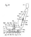
- the scale 1.1 is on the vehicle floor fixed guide rail 20a of a seat adjustment or with another part fixed to the vehicle floor connected, the scale 1.1 essentially in Direction of displacement of the seat extends.
- the sensor 6 is with a part attached to the top rail, e.g. one Cover plate (not shown) connected or it is Part of a traveling control electronics 60a.
- FIG For the purpose of determining the seat height a scale 1.2, the via a connecting rod 100 in the joint 100a on the not height-adjustable with respect to the vehicle floor
- Upper rail 20b is mounted and is essentially vertical extends.
- the assigned sensor 6 is in the on the seat cushion support (ST) specified control electronics 60b integrated.
- ST seat cushion support
- the simultaneous relative movement in the X direction can by the joint 100a or by an elastic trained connecting rod are balanced.
- the superimposition of the two movements as a result of the chosen one constructive adjustment kinematics is a matter of course taken into account when evaluating the measurement signals.
- the seat height can also be adjusted using the angle of inclination determine a pivot lever 21b by the 1.3 scale with respect to the pivot axis of the lever 21b trained and arranged in a circular arc and the assigned Sensor 6 with a part fixed to the upper rail 20b (e.g. control electronics).
- the length measuring system is part of a device for seat occupancy detection or for sensing the occupancy weight should be a 1.4 scale, which is about a connecting rod 102 is attached to a seat spring 101 is substantially vertical along an electronic Control unit 60b be guided.
- the control unit 60b has a sensor 6, which the measurement signals of the movable scale 1.4 generated.
- a shift of scale 1.4 occurs when the in the joints 100b, 100c mounted seat spring 101 due to the weight F of a user deflects. The one evoked translational shift of the scale 1.4 corresponds in their measure of weight.
- Measuring system can also be installed in the backrest.
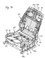
- Figure 14 is the scale 1.15 at the free end of a Joint 100d connected connecting rod 104 is arranged and guided in a guide sleeve over a connecting rod 100e at the upper end of the backrest R in the joint 100e is attached.
- a load on the backrest R parts 1.15, 103a, 103b, 104 are pushed backwards, with its arcuate contour becoming more and more flattens and the scale 1.15 further into the guide sleeve 103a is pushed into it.
- the one on the guide sleeve 103a attached sensor 6 takes the associated measurement signals and forwards them to an evaluation unit.
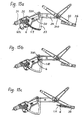
- FIGS Integration of the length measuring system in an adjustment device represented by a window regulator Different variants of the are shown in FIGS Integration of the length measuring system in an adjustment device represented by a window regulator.
- the 1.9 scale extends parallel to the toothing of the Toothed segment lever 33, which on the base plate 30 in the Axis 330 rotatably and fixed with the drive lever 34 connected is.
- the drive lever 34 is in the universal joint 340 hinged to the compensating lever 35, one of which End slidably supported in the guide rail 36.
- the free ends of the drive lever 34 and the compensating lever 35 are with fasteners, not shown the window pane in connection.
- the gear area the toothed segment lever 33 stands with a pinion of the transmission 32 engaged, in the housing of the magnetized Scale 1.9 assigned sensor 6 is integrated. If the motor 31 is put into operation, the toothed segment lever pivots 33 around the axis 330 and thereby guides the scale 1.9 past the sensor 6.
- the generated signals are evaluated by the electronics unit 60c and
- Adequate for the very important upper closing area To be able to evaluate safely can be a correspondingly higher one Resolution of the scale can be provided in this area.
- a sensitive pinch protection can also be used be ensured like a so-called soft stop at Reaching the end positions.
- the magnetized one can be used to control a window regulator Scale 1.17 also on a substantially in Edge of a window pane Arrange 70 (see Figure 19).
- the assigned sensor 6 is in the door body 71 or an electronic control device placed.
- the advantage of this variant lies mainly in the fact that the settlement behavior of the Adjustment mechanism can not affect.
- the sensor should preferably be in the stationary housing and the magnetized Scale on a moving locking part or on a connected part (e.g. actuation linkage) attached his.
Landscapes
- Physics & Mathematics (AREA)
- General Physics & Mathematics (AREA)
- Measurement Of Length, Angles, Or The Like Using Electric Or Magnetic Means (AREA)
- Transmission And Conversion Of Sensor Element Output (AREA)
Description
- Fig. 1 -
- einen kreisrunden Maßstab mit Magnetisierungsrichtung in der Querschnittsfläche,
- Fig. 2 -
- einen kreisrunden Maßstab mit Bereichen konstanter Magnetisierungsrichtung,
- Fig. 3 -
- einen Maßstab mit einem in der Nähe angeordneten Winkelsensor in fünf zeitlich nacheinander möglichen Positionen,
- Fig. 4 -
- einen homogen magnetisierten Querschnitt eines Maßstabes,
- Fig. 5 -
- einen mehrpolig magnetisierten Querschnitt eines Maßstabes,
- Fig. 6 -
- einen Querschnitt eines Maßstabes mit konzentrischen Teilen dauermagnetischen und nicht dauermagnetischen Materials,
- Fig. 7 -
- einen Querschnitt eines Maßstabes, bei dem das dauermagnetische Material das nicht magnetische Material nicht umschließt,
- Fig. 8 -
- einen Querschnitt eines Maßstabes mit mechanisch widerstandsfähigem Profil des nicht dauermagnetischen Teiles,
- Fig. 9 -
- einen Maßstab mit einem Winkelsensor,
- Fig. 10 -
- einen Maßstab mit zwei Winkelsensoren in der Ebene des Querschnitts des Maßstabes,
- Fig. 11 -
- die Seitenansicht eines Längenmeßsystems mit gleichmäßiger Periodenlänge der Drehung der Magnetisierung,
- Fig. 12 -
- die Seitenansicht eines Längenmeßsystems mit zwei in Meßrichtung gegeneinander versetzten Winkelsensoren und einem Diagramm der quadratischen Winkelzunahme mit der Position.
- Fig. 13 -
- schematische Darstellung der Seitenansicht eines längs- und höhenverstellbaren Fahrzeugsitzes mit mehreren erfindungsgemäßen Meßsystemen;
- Fig. 14 -
- perspektivische Darstellung der metallischen Struktur eines Kraftfahrzeugsitzes mit mehreren schematisch angedeuteten erfindungsgemäßen Meßsystemen;
- Fig. 15a -
- Kreuzarmfensterheber mit einem sich entlang des Verzahnungsbereiches erstreckenden magnetischen Maßstab;
- Fig. 15b -
- Kreuzarmfensterheber mit einem sich in der Nähe der Schwenkachse des Zahnsegmenthebels bogenförmig erstreckenden magnetischen Maßstab;
- Fig. 15c -
- Kreuzarmfensterheber mit einem entlang der Führungsschiene des Ausgleichshebels verschiebbaren magnetischen Maßstab;
- Fig. 16 -
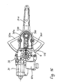
- Einarmfensterheber mit einem mit dem Antrieb gekoppelten und verschiebbaren magnetischen Maßstab;
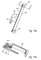
- Fig. 17a -
- Seitenansicht der Führungsschiene eines Seilfensterhebers mit einem sich in Verschieberichtung erstreckenden magnetischen Maßstab;
- Fig. 17b -
- Schnittdarstellung durch die Führungsschiene im Bereich des mit der Fensterscheibe verbundenen Mitnehmers;
- Fig. 18a -
- schematische Schnittdarstellung durch einen Antrieb mit einem ringförmigen magnetisierten Element;
- Fig. 18b -
- schematische Schnittdarstellung eines Antriebs mit einem magnetisierten Element in Form eines umlaufenden Riemens;
- Fig. 19 -
- schematische Schnittdarstellung durch einen Antrieb mit einer Seiltrommel und einem quer zur Rotationsachse verschiebbaren magnetischen Maßstab;
- Fig. 20 -
- Kraftfahrzeugtür mit einem an der vertikalen Scheibenkante angeordneten magnetischen Maßstab.
Claims (53)
- Längenmeßsystem mit mindestens einem magnetischen Maßstab (1) und mindestens einem Magnetfeldsensor (6), der in Meßrichtung (7) relativ zu dem Maßstab (1) verschiebbar ist, wobei die Magnetisierung (2) des Maßstabes (1) eine Komponente in einer Ebene aufweist, die senkrecht auf der Meßrichtung (7) steht und wobei die Längsposition des Magnetfeldsensors (6) relativ zu dem Maßstab (1) aus der Richtung der Komponente der Magnetisierung (2) bestimmbar ist,
dadurch gekennzeichnet, daß sich die Richtung dieser Komponente der Magnetisierung (2) entlang der Meßrichtung (7) derart ändert, daß jeder Längsposition des Magnetfeldsensors (6) eine Richtung der Komponente der Magnetisierung (2) innerhalb des Maßstabes (1) an dieser Längsposition zugeordnet ist, aus der die Längsposition bestimmbar ist. - Längenmeßsystem nach Anspruch 1, dadurch gekennzeichnet, daß sich der Winkel der Komponente der Magnetisierung (2) bezüglich einer Referenzlinie, die senkrecht auf der Meßrichtung (7) steht, mit dem Fortschreiten in Meßrichtung (7) kontinuierlich ändert.
- Längenmeßsystem nach Anspruch 2, dadurch gekennzeichnet, daß sich der Winkel (3) der Komponente der Magnetisierung (2) linear ändert und mit einer konstanten Periodenlänge (4) entlang der Meßrichtung (7) variiert.
- Längenmeßsystem nach Anspruch 1, dadurch gekennzeichnet, daß der Winkel (3) der Komponente der Magnetisierung (2) bezüglich einer Referenzlinie, die senkrecht auf der Meßrichtung (7) steht, in Bereichen (5) stufenweise mit dem Fortschreiten in Meßrichtung (7) eingestellt ist.
- Längenmeßsystem nach Anspruch 1, dadurch gekennzeichnet, daß der Querschnitt (9) eines Maßstabes (1) homogen (2.1) magnetisiert ist.
- Längenmeßsystem nach Anspruch 1, dadurch gekennzeichnet, daß der Querschnitt (9) eines Maßstabes (1) mehrpolig (2.2) magnetisiert ist.
- Längenmeßsystem nach Anspruch 1, dadurch gekennzeichnet, daß der Querschnitt (9.1) des Maßstabes (1) rund ist.
- Längenmeßsystem nach Anspruch 1, dadurch gekennzeichnet, daß der Querschnitt (9.2) des Maßstabs (1) einen nicht dauermagnetischen Kern (10) hat.
- Längenmeßsystem nach Anspruch 8, dadurch gekennzeichnet, daß der Querschnitt (9.3) des Maßstabes (1) den nicht dauermagnetischen Kern (10) nicht umschließt.
- Längenmeßsystem nach Anspruch 8 oder 9, dadurch gekennzeichnet, daß der nicht dauermagnetische Kern (10) weichmagnetisch ist.
- Längenmeßsystem nach Anspruch 8, dadurch gekennzeichnet, daß der nicht dauermagnetische Kern (10) ein Profil (11) hat und so als Träger des Maßstabes (1) mit dem Querschnitt (9.4) geeignet ist.
- Längenmeßsystem nach Anspruch 1, dadurch gekennzeichnet, daß der mindestens eine Magnetfeldsensor (6) ein magnetoresistiver Winkelsensor (12) ist.
- Längenmeßsystem nach Anspruch 12, dadurch gekennzeichnet, daß an einem Maßstab (1) genau gegenüberliegend am Querschnitt (9) zwei gleiche magnetoresistive Winkelsensoren (12, 13) vorhanden sind, um Fehler aus einer seitlichen Verschiebung des Maßstabs (1) zu korrigieren.
- Längenmeßsystem nach Anspruch 7, dadurch gekennzeichnet, daß der runde Maßstab (1) in Form einer regelmäßigen Schraubenlinie magnetisiert ist und ein magnetoresistiver Winkelsensor (14) entlang der Meßrichtung (16) periodische Signale abgibt.
- Längenmeßsystem nach Anspruch 14, dadurch gekennzeichnet, daß die Magnetisierung über die gesamte Länge des Maßstabes (1) nur um 180 ° verdreht ist und so aus dem Signal des magnetoresistiven Winkelsensors (14) die Absolutposition ermittelbar ist.
- Längenmeßsystem nach Anspruch 7, dadurch gekennzeichnet, daß der runde Maßstab (17) vom Anfang her in radialer Richtung mit ständig abnehmender Periodenlänge magnetisiert ist und ein Paar (18) magnetoresistive Winkelsensoren in einem Abstand angeordnet ist, der. der ersten Periodenlänge am Anfang des Maßstabes (17) entspricht, und daß die Position aus der Winkeldifferenz des Paares der magnetoresistiven Winkelsensoren ermittelbar ist, um Fehler durch eine spontane Drehung des Maßstabes (17) auszuschließen.
- Längenmeßsystem nach Anspruch 16, dadurch gekennzeichnet, daß der Abstand des Paares (18) magnetoresistiver Winkelsensoren am Ende des Maßstabes (17) zwei Periodenlängen entspricht und daß so aus der Winkeldifferenz des Paares (18) magnetoresistiver Winkelsensoren die Position absolut ermittelbar ist.
- Längenmeßsystem nach Anspruch 4, dadurch gekennzeichnet, daß den jeweiligen Richtungen der Magnetisierungen (2) in den Bereichen (5) jeweils ein Wert eines mehrstufigen Codes zugeordnet ist.
- Längenmeßsystem nach Anspruch 18, dadurch gekennzeichnet, daß der mehrstufige Code vierwertig ist.
- Längenmeßsystem nach Anspruch 18, dadurch gekennzeichnet, daß der mehrstufige Code ein Dezimalcode ist.
- Längenmeßsystem nach Anspruch 18, dadurch gekennzeichnet, daß sich ein bestimmter Winkelbereich der Richtung der Magnetisierung (2), der keinem Codewert entspricht, in Sonderbereichen befindet, die in regelmäßigen Abständen vorhanden sind und so die Erkennung eines Wortanfangs ermöglicht ist.
- Längenmeßsystem nach Anspruch 21, dadurch gekennzeichnet, daß sich der Winkel der Richtung der Magnetisierung (2) in dem Sonderbereich kontinuierlich mit der Position ändert.
- Längenmeßsystem nach einem der Ansprüche 18 bis 22, dadurch gekennzeichnet, daß zur Codeerkennung die doppelte Anzahl der Stellen des Codes von magnetoresistiven Winkelsensoren vorhanden ist, deren Abstand der halben Länge der Bereiche (5) entspricht.
- Längenmeßsystem nach Anspruch 1, dadurch gekennzeichnet, daß zwei parallele Maßstäbe (1) gleicher Länge mit unterschiedlicher Periodenlänge (4) und einer um eins verschiedenen Periodenzahl mit jeweils einem in Meßrichtung bei gleichem Wert befindlichen magnetoresistiven Winkelsensor vorhanden sind, so daß die Position aus den Winkeln der beiden magnetoresistiven Winkelsensoren absolut ermittelbar ist.
- Verwendung des Längenmeßsystems nach wenigstens einem der Ansprüche 1 bis 24, dadurch gekennzeichnet, daß der Maßstab (1.1 - 1.17) oder der zugeordnete Sensor (6) mit der Verstellmechanik einer Verstelleinrichtung für ein Kraftfahrzeug in Wirkverbindung steht.
- Verwendung nach Anspruch 25, dadurch gekennzeichnet, daß das Längenmeßsystem Bestandteil einer Sitzverstelleinrichtung ist, insbesondere einer Einrichtung zur Sitzlängsverstellung, Sitzhöhenverstellung, Sitzlehnenneigungsverstellung, Kopfstützen-höhenverstellung oder Sitzkissentiefenverstellung.
- Verwendung nach Anspruch 26, dadurch gekennzeichnet, daß der Maßstab (1.1) mit einer am Fahrzeugboden festgelegten Führungsschiene (20a) einer Sitzlängsverstellung oder mit einem sonstigen fahrzeugbodenfesten Teil verbunden ist, wobei sich der Maßstab (1.1) im wesentlichen in Verschieberichtung des Sitzes erstreckt, und daß der Sensor (6) mit einem an der Oberschiene (20b) festgelegten Teil verbunden ist.
- Verwendung nach Anspruch 26, dadurch gekennzeichnet, daß der Maßstab (1.2) an einem bezüglich des Fahrzeugbodens nicht höhenverstellbaren Teil, z.B. an der Oberschiene (20b) einer Einrichtung zur Sitzlängsverstellung, lagert und sich im wesentlichen vertikal erstreckt und daß der zugeordnete Sensor (6) am Sitzkissenträger (ST) festgelegt ist.
- Verwendung nach Anspruch 26, dadurch gekennzeichnet, daß der Maßstab (1.3) mit einem schwenkbar gelagerten Hebel (21b) einer Sitzhöhen- oder Sitzneigungsverstellung verbunden ist und daß der zugeordnete Sensor (6) mit dem Teil (20b) direkt oder indirekt verbunden ist, an das mit dem Sensor (6) ausgerüstete Ende des schwenkbaren Hebels (21b) lagert.
- Verwendung nach Anspruch 29, dadurch gekennzeichnet, daß der Maßstab (1.3) bezüglich der Schwenkachse des Hebels (21b) kreisbogenförmig ausgebildet ist.
- Verwendung nach Anspruch 26, dadurch gekennzeichnet, daß der Maßstab (1.6) mit einem drehbar gelagerten Getriebeelement einer Einrichtung (22) zur Lehnenneigungsverstellung verbunden ist und daß der zugeordnete Sensor (6) mit einem getriebegehäusefesten Teil verbunden ist.
- Verwendung nach Anspruch 26, dadurch gekennzeichnet, daß der Maßstab (1.6) mit einen lehnenfesten Teil und der zugeordnete Sensor (6) mit einem sitzuntergestellfesten Teil verbunden ist oder umgekehrt.
- Verwendung nach Anspruch 31 oder 32, dadurch gekennzeichnet, daß der Maßstab (1.6) bezüglich der Lehnenschwenkachse kreisbogenförmig ausgebildet ist.
- Verwendung nach Anspruch 26, dadurch gekennzeichnet, daß der Maßstab (1.7) mit der Oberschenkelauflage (23) einer Sitzkissentiefenverstellung verbunden ist und daß der zugeordnete Sensor (6) am Sitzkissenträger befestigt ist.
- Verwendung nach Anspruch 26, dadurch gekennzeichnet, daß der Maßstab (1.8) mit dem Rückenlehnenträger (RT) und der zugeordnete Sensor (6) mit einem mit der Kopfstütze (K) festen Teil verbunden ist oder umgekehrt.
- Verwendung nach Anspruch 35, dadurch gekennzeichnet, daß der Sensor (6) mit einem Getriebe (24b) in Verbindung steht, das entlang eines sich in Verstellrichtung erstreckenden Getriebeelementes (24a) bewegbar ist.
- Verwendung nach Anspruch 26, dadurch gekennzeichnet, daß das Längenmeßsystem Bestandteil eine Vorrichtung zur Sitzbelegungserkennung und/oder zur Sensierung des Belegungsgewichts ist.
- Verwendung nach Anspruch 37, dadurch gekennzeichnet, daß der Maßstab (1.4) an einem mit dem Sitzkissen (S) in Verbindung stehenden Teil befestigt ist und daß der zugeordnete Sensor (6) am Sitzkissenträger (ST) festgelegt ist.
- Verwendung nach Anspruch 37, dadurch gekennzeichnet, daß der Maßstab (1.5) in einer Führungshülse (103a), an der der zugeordnete Sensor (6) befestigt ist, derart lagert, daß bei einer Sitzbelegung in Abhängigkeit von der Stärke der Belastung eine Verschiebung zwischen dem Maßstab (1.5) und dem Sensor (6) erzeugt wird.
- Verwendung nach wenigstens einem der Ansprüche 25 bis 39, dadurch gekennzeichnet, daß der Sensor (6) direkter Bestandteil einer elektronischen Steuerungseinrichtung (60a - 60c) ist.
- Verwendung nach Anspruch 25, dadurch gekennzeichnet, daß das Längenmeßsystem Bestandteil eines Fensterhebers ist.
- Verwendung nach Anspruch 41, dadurch gekennzeichnet, daß sich der Maßstab (1.9) parallel zur Verzahnung des Zahnsegmenthebels (33) eines Armfensterhebers erstreckt und daß der zugeordnete Sensor (6) in die Antriebseinheit integriert ist.
- Verwendung nach Anspruch 41, dadurch gekennzeichnet, daß sich der Maßstab (1.10) in der Nähe der Schwenkachse (330) des Zahnsegmenthebels (33) kreisbogenförmig erstreckt und daß der zugeordnete Sensor (6) an einem mit der Türkarosserie verbundenen Teil (30) befestigt ist.
- Verwendung nach Anspruch 41, dadurch gekennzeichnet, daß der Maßstab (1.11) mit einem in der Führungsschiene (36) eines Kreuzarmfensterhebers geführten Gleiter verschiebbar verbunden ist und daß der zugeordnete Sensor (6) an einem mit der Türkarosserie verbundenen Teil befestigt ist.
- Verwendung nach Anspruch 41, dadurch gekennzeichnet, daß der Maßstab (1.12) mittels eines der Meßvorrichtung zugeordnetes Getriebe, das Bestandteil einer Antriebseinheit eines Fensterhebers oder mit dieser gekoppelt ist, synchron mit der Fensterscheibe verstellbar ist und daß der zugeordnete Sensor (5) in die Antriebseinheit integriert ist.
- Verwendung nach Anspruch 41, dadurch gekennzeichnet, daß sich der Maßstab (1.13) entlang der Führungsschiene (40) eines Seilfensterhebers erstreckt und daß der Sensor (6) in den mit der Fensterscheibe verbundenen Mitnehmer integriert ist.
- Verwendung nach Anspruch 41, dadurch gekennzeichnet, daß der Maßstab (1.14) ringförmig ausgebildet und mit einer Seiltrommel (44) verbunden ist und daß der zugeordnete Sensor (6) am Getriebegehäuse (48) festgelegt ist.
- Verwendung nach Anspruch 41, dadurch gekennzeichnet, daß der Maßstab (1.15) als ein geschlossenes umlaufendes Bad, Riemen oder dergleichen ausgebildet ist, der über eine Drehachse der Antriebseinheit antreibbar und einem gehäusefesten Sensor (6) zugeordnet ist.
- Verwendung nach Anspruch 48, dadurch gekennzeichnet, daß der umlaufende Maßstab (1.15) über eine Untersetzung mit der Antriebseinheit derart gekoppelt ist, daß der Maßstab (1.15) beim Durchlaufen des Verstellweges einmal umläuft.
- Verwendung nach Anspruch 41, dadurch gekennzeichnet, daß der Maßstab (1.16) einen Nocken (51) aufweist, der in die schraubenförmig umlaufende Seilrille einer Seiltrommel eingreift und den Maßstab (1.16) bei Drehung der Seiltrommel (50) verschiebt, und daß der Sensor (6) im Gehäuse der Antriebseinheit integriert ist.
- Verwendung nach Anspruch 25, dadurch gekennzeichnet, daß der Maßstab (1.17) an der im wesentlichen vertikalen Kante einer Fensterscheibe (70) angeordnet und einem in der Türkarosserie (71) plazierten Sensor (6) zugeordnet ist.
- Verwendung nach Anspruch 25, dadurch gekennzeichnet, daß der Maßstab zur Erkennung der Schließlage in einem Kraftfahrzeugtürschloß angeordnet ist.
- Verwendung nach wenigstens einem der voranstehenden Ansprüche 25-52, dadurch gekennzeichnet, daß der Sensor (6) mit einer Einrichtung zur drahtlosen Signalübermittlung verbunden ist, die die Meßsignale an eine elektronische Steuerungseinrichtung sendet.
Applications Claiming Priority (3)
| Application Number | Priority Date | Filing Date | Title |
|---|---|---|---|
| DE19910636A DE19910636A1 (de) | 1999-03-10 | 1999-03-10 | Längenmeßsystem, bestehend aus einem oder mehreren magnetischen Maßstäben |
| DE19910636 | 1999-03-10 | ||
| PCT/DE2000/000788 WO2000054010A1 (de) | 1999-03-10 | 2000-03-10 | Längenmesssystem mit mindestens einem magnetischen massstab |
Publications (2)
| Publication Number | Publication Date |
|---|---|
| EP1157256A1 EP1157256A1 (de) | 2001-11-28 |
| EP1157256B1 true EP1157256B1 (de) | 2004-05-06 |
Family
ID=7900451
Family Applications (1)
| Application Number | Title | Priority Date | Filing Date |
|---|---|---|---|
| EP00922432A Expired - Lifetime EP1157256B1 (de) | 1999-03-10 | 2000-03-10 | Längenmesssystem mit mindestens einem magnetischen massstab |
Country Status (5)
| Country | Link |
|---|---|
| US (1) | US6545463B1 (de) |
| EP (1) | EP1157256B1 (de) |
| DE (2) | DE19910636A1 (de) |
| ES (1) | ES2219334T3 (de) |
| WO (1) | WO2000054010A1 (de) |
Cited By (2)
| Publication number | Priority date | Publication date | Assignee | Title |
|---|---|---|---|---|
| DE102005055905A1 (de) * | 2005-11-22 | 2007-05-24 | Continental Teves Ag & Co. Ohg | Längenmessanordnung mit einem magnetischen Maßstab mit gegenläufiger Magnetisierung |
| WO2024227739A1 (de) * | 2023-05-04 | 2024-11-07 | Vega Grieshaber Kg | Feldgerät mit drehring |
Families Citing this family (43)
| Publication number | Priority date | Publication date | Assignee | Title |
|---|---|---|---|---|
| EP1074818A3 (de) * | 1999-08-06 | 2001-10-31 | Siemens Aktiengesellschaft | Positionsbestimmungseinrichtung |
| US6448763B1 (en) * | 2001-01-10 | 2002-09-10 | Siemens Corporation | System for magnetization to produce linear change in field angle |
| DE10162849B4 (de) | 2001-12-20 | 2007-11-29 | Sensitec Gmbh | Längenmesssystem, bei dem ein Massstab relativ zur Position von beabstandeten Längensensoren bewegt wird |
| DE10225845B4 (de) * | 2002-06-05 | 2007-02-01 | Bizerba Gmbh & Co. Kg | Aufschnitt-Schneidemaschine und Verfahren zum Betreiben einer Aufschnitt-Schneidemaschine |
| US6909281B2 (en) | 2002-07-03 | 2005-06-21 | Fisher Controls International Llc | Position sensor using a compound magnetic flux source |
| DE20210548U1 (de) * | 2002-07-04 | 2003-08-28 | Brose Fahrzeugteile | Schaltung zur Bestimmung der Position einer Verstelleinrichtung in einem Kraftfahrzeug |
| BRPI0407499B1 (pt) | 2003-02-21 | 2017-12-19 | Fisher Controls International Llc | Position sensor assembly, and, method for detecting relative position |
| DE10340203A1 (de) * | 2003-08-28 | 2005-03-24 | Brose Fahrzeugteile Gmbh & Co. Kommanditgesellschaft, Coburg | Verstelleinrichtung für ein Kraftfahrzeug |
| GB0412122D0 (en) * | 2004-05-29 | 2004-06-30 | Farrow Michael J | Magnetic encoder |
| US7075416B2 (en) * | 2004-06-21 | 2006-07-11 | Honeywell International Inc. | Automotive universal latch control implementation |
| JP4624043B2 (ja) * | 2004-09-14 | 2011-02-02 | 株式会社デンソー | 回転検出装置 |
| US7741839B2 (en) * | 2005-10-20 | 2010-06-22 | Cts Corporation | Non-contacting position sensor using a rotating magnetic vector |
| FR2898189B1 (fr) * | 2006-03-02 | 2008-10-17 | Moving Magnet Tech | Capteur de position a direction d'aimantation variable et procede de realisation |
| DE102006045827A1 (de) * | 2006-09-22 | 2008-04-10 | Dichtungstechnik G. Bruss Gmbh & Co. Kg | Axialverschiebbares Bauteil insbesondere in einem Kraftfahrzeugmotor oder -getriebe |
| DE102007008870A1 (de) | 2007-02-21 | 2008-09-04 | Hl-Planar Technik Gmbh | Anordnung und Verfahren zur Absolutbestimmung der Linearposition oder der durch einen Winkel ausgedrückten Drehposition |
| DE102007050527A1 (de) * | 2007-10-19 | 2009-04-23 | Hiflex Software Gmbh | Verfahren zum Herstellen eines Druckprodukts und Bestellsystem für Druckprodukte |
| US7834617B2 (en) * | 2008-01-22 | 2010-11-16 | Ford Global Technologies, Llc | Magnetoresistive continuous seat track position sensor |
| FR2936307B1 (fr) | 2008-09-24 | 2010-09-17 | Moving Magnet Tech Mmt | Capteur de position lineaire ou rotatifa aimant permanent pour la detection d'une cible ferromagnetique |
| FR2937722B1 (fr) | 2008-10-24 | 2010-11-26 | Moving Magnet Tech Mmt | Capteur de position magnetique a mesure de direction de champ et a collecteur de flux |
| FR2947902B1 (fr) | 2009-07-07 | 2011-07-22 | Moving Magnet Technologies M M T | Capteur de position absolue et multi-periodique |
| FR2952430B1 (fr) | 2009-11-06 | 2012-04-27 | Moving Magnet Technologies M M T | Capteur de position magnetique bidirectionnel a rotation de champ |
| US20120242331A1 (en) * | 2009-12-04 | 2012-09-27 | Werner Dengler | Hall-based rotational angle measuring system, in particular for hand-operated throttles |
| DE102010019077A1 (de) | 2010-04-30 | 2011-11-03 | Continental Automotive Gmbh | Magnetisches Längenmesssystem, Längenmessverfahren sowie Herstellungsverfahren eines magnetischen Längenmesssystems |
| WO2012010311A1 (de) * | 2010-07-23 | 2012-01-26 | Hirschmann Automotive Gmbh | Lineare wegmessung mit hilfe eines magnetsystemes bestehend aus einzelmagneten |
| FR2965347B1 (fr) | 2010-09-29 | 2015-04-03 | Moving Magnet Tech | Capteur de position ameliore |
| DE102011008880A1 (de) | 2011-01-18 | 2012-07-19 | Sensitec Gmbh | Anordnung und Verfahren zur Erfassung von Absolutpositionen eines Messkopfs mit einer Reihe magnetischer Sensoren |
| EP2568259B1 (de) * | 2011-09-06 | 2019-04-03 | Carl Freudenberg KG | Encoderring und Anordnung |
| US10434916B2 (en) | 2013-12-27 | 2019-10-08 | Ts Tech Co., Ltd. | Seat with wakefulness-maintaining device |
| DE102016102978B4 (de) | 2016-02-19 | 2018-03-01 | Infineon Technologies Ag | Magnetischer Positionssensor |
| EP3299770B1 (de) * | 2016-09-22 | 2020-06-03 | Sagentia Limited | Induktive sensorvorrichtung |
| CN106705786B (zh) * | 2016-11-30 | 2023-05-16 | 江西合力泰科技有限公司 | 一种用于测量截面为n边形的产品外形的通止规 |
| DE102017222677A1 (de) * | 2016-12-29 | 2018-07-05 | Robert Bosch Gmbh | Sensoreinrichtung |
| US10690520B2 (en) * | 2017-02-27 | 2020-06-23 | The Boeing Company | Apparatus, system, and method for determining a position of a part |
| WO2019139613A1 (en) * | 2018-01-12 | 2019-07-18 | Honeywell International Inc. | Magnetic encoding for smart position sensor range extension |
| FR3082615B1 (fr) | 2018-06-15 | 2020-10-16 | Electricfil Automotive | Methode de determination d'une position angulaire relative entre deux pieces |
| DE102018211500A1 (de) * | 2018-07-11 | 2020-01-16 | Infineon Technologies Ag | Vorrichtung und Verfahren zur Bestimmung der Lage eines Permanentmagneten |
| FR3087256B1 (fr) | 2018-10-15 | 2020-10-30 | Electricfil Automotive | Methode et systeme capteur de determination d'une position angulaire relative entre deux pieces, et procede de fabrication d'un corps magnetique |
| DE102019103522A1 (de) * | 2019-02-12 | 2020-08-13 | Novotechnik Messwertaufnehmer OHG | Sensorvorrichtung und Betriebsverfahren hierfür |
| DE102019216988B4 (de) * | 2019-11-05 | 2025-12-04 | Schaeffler Technologies AG & Co. KG | Positionsmesssystem |
| CN113860100B (zh) * | 2021-10-21 | 2023-03-03 | 杭州浙达精益机电技术股份有限公司 | 一种电梯轿厢绝对位置的测量方法和装置 |
| CN115128526B (zh) * | 2022-09-02 | 2022-12-16 | 国网山东省电力公司枣庄供电公司 | 一种变电站用旋转式磁变量测量设备及测量方法 |
| CN116312133B (zh) * | 2023-03-28 | 2025-11-18 | 一汽丰田汽车有限公司 | 过坑训练装置 |
| CN118731577B (zh) * | 2024-06-25 | 2024-12-03 | 西安天尔信息技术咨询有限公司 | 一种多工况适用的自垂直维稳电缆路径仪 |
Family Cites Families (6)
| Publication number | Priority date | Publication date | Assignee | Title |
|---|---|---|---|---|
| GB2071333B (en) | 1980-02-22 | 1984-02-01 | Sony Corp | Magnetic sensor device |
| US4757257A (en) * | 1984-05-28 | 1988-07-12 | Canon Kabushiki Kaisha | Magnetoresistive displacement sensor and signal processing circuit |
| DE4030450A1 (de) | 1990-09-26 | 1992-04-02 | Siemens Ag | Dreh- oder linearpositionsgeber |
| DE19521617C1 (de) | 1995-06-14 | 1997-03-13 | Imo Inst Fuer Mikrostrukturtec | Sensorchip zur Bestimmung eines Sinus- und eines Cosinuswertes sowie seine Verwendung zum Messen eines Winkels und einer Position |
| DE19729312A1 (de) | 1997-07-09 | 1999-01-14 | Inst Mikrostrukturtechnologie | Absolutes magnetisches Längenmeßsystem |
| TW419691B (en) * | 1999-03-30 | 2001-01-21 | Koninkl Philips Electronics Nv | Display device comprising a deflection unit and a deflection unit for a display device |
-
1999
- 1999-03-10 DE DE19910636A patent/DE19910636A1/de not_active Ceased
-
2000
- 2000-03-10 ES ES00922432T patent/ES2219334T3/es not_active Expired - Lifetime
- 2000-03-10 WO PCT/DE2000/000788 patent/WO2000054010A1/de not_active Ceased
- 2000-03-10 DE DE50006331T patent/DE50006331D1/de not_active Expired - Lifetime
- 2000-03-10 EP EP00922432A patent/EP1157256B1/de not_active Expired - Lifetime
- 2000-03-10 US US09/936,886 patent/US6545463B1/en not_active Expired - Lifetime
Cited By (3)
| Publication number | Priority date | Publication date | Assignee | Title |
|---|---|---|---|---|
| DE102005055905A1 (de) * | 2005-11-22 | 2007-05-24 | Continental Teves Ag & Co. Ohg | Längenmessanordnung mit einem magnetischen Maßstab mit gegenläufiger Magnetisierung |
| DE102005055905B4 (de) * | 2005-11-22 | 2016-10-27 | Continental Teves Ag & Co. Ohg | Längenmessanordnung mit einem magnetischen Maßstab mit gegenläufiger Magnetisierung |
| WO2024227739A1 (de) * | 2023-05-04 | 2024-11-07 | Vega Grieshaber Kg | Feldgerät mit drehring |
Also Published As
| Publication number | Publication date |
|---|---|
| WO2000054010A1 (de) | 2000-09-14 |
| ES2219334T3 (es) | 2004-12-01 |
| DE50006331D1 (de) | 2004-06-09 |
| EP1157256A1 (de) | 2001-11-28 |
| DE19910636A1 (de) | 2000-09-14 |
| US6545463B1 (en) | 2003-04-08 |
Similar Documents
| Publication | Publication Date | Title |
|---|---|---|
| EP1157256A1 (de) | Längenmesssystem mit mindestens einem magnetischen massstab | |
| EP1982147B1 (de) | Drehwinkelsensor sowie verfahren zum bestimmen der absoluten winkelstellung eines über mehrere runden drehbaren körpers | |
| EP0953494B1 (de) | Vorrichtung zur Bestimmung des Masses der Verdrehung zwischen zwei Teilen | |
| EP4095017B1 (de) | Lenkaktuator für ein lenksystem und lenksystem für ein kraftfahrzeug | |
| DE10037211B4 (de) | Lenkradstellungssensor | |
| EP0970000B1 (de) | Lenkwinkelsensorsystem mit erhöhter redundanz | |
| DE4134794A1 (de) | Weggeber fuer einen stellantrieb, insbesondere in einem fahrzeug | |
| WO2013186001A1 (de) | Magnetgeberring einer rotorlagesensorik eines elektrisch kommutierten elektromotors | |
| EP1917167A2 (de) | Elektromotorischer hilfsantrieb für fahrzeuge | |
| DE102020106785A1 (de) | Hinterachslenkung und Lenkwinkelmessung an der Hinterachse eines Kraftfahrzeugs | |
| DE112008000430T5 (de) | Linearer Positionssensor | |
| EP1129268B1 (de) | Vorrichtung zum erfassen der verstellung translatorisch bewegter verstelleinrichtungen in fahrzeugen | |
| DE102019115440A1 (de) | System und Verfahren zum Bestimmen einer Sitzgurtbandausgabe | |
| EP2363570B1 (de) | Rohrmotoranordnung für eine Verdunkelungsvorrichtung | |
| EP1312534B1 (de) | Vorrichtung zur Bestimmung des Lenkwinkels eines Lenkrades | |
| EP1321743B1 (de) | Absolutlängenmesssystem, bei dem ein Massstab relativ zur Position von beabstandeten Längesensoren bewegt wird | |
| DE102020108676A1 (de) | Steer-by-Wire-Lenksystem | |
| EP1308371B1 (de) | Verfahren und Vorrichtung zur Fassung der Ist-Stellung eines zu lenkenden Rades bei einem Flurförderzeug mit einer elektrischen Lenkung | |
| EP2947353B1 (de) | Triebachse für ein fahrzeug | |
| EP4609092B1 (de) | Verfahren zur positionsbestimmung einer schaltwalze | |
| DE19924995A1 (de) | Anordnung und Verfahren zur Erfassung der Translationslage eines Stellelements in einem Getriebe | |
| DE19919200A1 (de) | Verfahren zur Endlagenbestimmung von Toren sowie Torantrieb zur Durchführung des Verfahrens | |
| EP0650107A1 (de) | Steuersystem für motorische Antriebe | |
| WO2024256052A1 (de) | Lenkaktuator für ein steer-by-wire-lenksystem eines kraftfahrzeugs und verfahren zum betrieb eines lenkaktuators | |
| DE102007055098B4 (de) | Erfassungsanordnung |
Legal Events
| Date | Code | Title | Description |
|---|---|---|---|
| PUAI | Public reference made under article 153(3) epc to a published international application that has entered the european phase |
Free format text: ORIGINAL CODE: 0009012 |
|
| 17P | Request for examination filed |
Effective date: 20010928 |
|
| AK | Designated contracting states |
Kind code of ref document: A1 Designated state(s): AT BE CH CY DE DK ES FI FR GB GR IE IT LI LU MC NL PT SE |
|
| GRAP | Despatch of communication of intention to grant a patent |
Free format text: ORIGINAL CODE: EPIDOSNIGR1 |
|
| GRAS | Grant fee paid |
Free format text: ORIGINAL CODE: EPIDOSNIGR3 |
|
| GRAA | (expected) grant |
Free format text: ORIGINAL CODE: 0009210 |
|
| AK | Designated contracting states |
Kind code of ref document: B1 Designated state(s): DE ES FR GB IT SE |
|
| REG | Reference to a national code |
Ref country code: GB Ref legal event code: FG4D Free format text: NOT ENGLISH |
|
| REF | Corresponds to: |
Ref document number: 50006331 Country of ref document: DE Date of ref document: 20040609 Kind code of ref document: P |
|
| REG | Reference to a national code |
Ref country code: IE Ref legal event code: FG4D Free format text: GERMAN |
|
| GBT | Gb: translation of ep patent filed (gb section 77(6)(a)/1977) |
Effective date: 20040701 |
|
| PG25 | Lapsed in a contracting state [announced via postgrant information from national office to epo] |
Ref country code: SE Free format text: LAPSE BECAUSE OF FAILURE TO SUBMIT A TRANSLATION OF THE DESCRIPTION OR TO PAY THE FEE WITHIN THE PRESCRIBED TIME-LIMIT Effective date: 20040806 |
|
| REG | Reference to a national code |
Ref country code: ES Ref legal event code: FG2A Ref document number: 2219334 Country of ref document: ES Kind code of ref document: T3 |
|
| REG | Reference to a national code |
Ref country code: IE Ref legal event code: FD4D |
|
| ET | Fr: translation filed | ||
| PLBE | No opposition filed within time limit |
Free format text: ORIGINAL CODE: 0009261 |
|
| STAA | Information on the status of an ep patent application or granted ep patent |
Free format text: STATUS: NO OPPOSITION FILED WITHIN TIME LIMIT |
|
| 26N | No opposition filed |
Effective date: 20050208 |
|
| PGFP | Annual fee paid to national office [announced via postgrant information from national office to epo] |
Ref country code: IT Payment date: 20100320 Year of fee payment: 11 Ref country code: FR Payment date: 20100324 Year of fee payment: 11 |
|
| PGFP | Annual fee paid to national office [announced via postgrant information from national office to epo] |
Ref country code: GB Payment date: 20100310 Year of fee payment: 11 |
|
| PGFP | Annual fee paid to national office [announced via postgrant information from national office to epo] |
Ref country code: ES Payment date: 20100408 Year of fee payment: 11 |
|
| PGFP | Annual fee paid to national office [announced via postgrant information from national office to epo] |
Ref country code: DE Payment date: 20110331 Year of fee payment: 12 |
|
| GBPC | Gb: european patent ceased through non-payment of renewal fee |
Effective date: 20110310 |
|
| REG | Reference to a national code |
Ref country code: FR Ref legal event code: ST Effective date: 20111130 |
|
| PG25 | Lapsed in a contracting state [announced via postgrant information from national office to epo] |
Ref country code: FR Free format text: LAPSE BECAUSE OF NON-PAYMENT OF DUE FEES Effective date: 20110331 |
|
| PG25 | Lapsed in a contracting state [announced via postgrant information from national office to epo] |
Ref country code: IT Free format text: LAPSE BECAUSE OF NON-PAYMENT OF DUE FEES Effective date: 20110310 Ref country code: GB Free format text: LAPSE BECAUSE OF NON-PAYMENT OF DUE FEES Effective date: 20110310 |
|
| REG | Reference to a national code |
Ref country code: ES Ref legal event code: FD2A Effective date: 20120424 |
|
| PG25 | Lapsed in a contracting state [announced via postgrant information from national office to epo] |
Ref country code: ES Free format text: LAPSE BECAUSE OF NON-PAYMENT OF DUE FEES Effective date: 20110311 |
|
| REG | Reference to a national code |
Ref country code: DE Ref legal event code: R119 Ref document number: 50006331 Country of ref document: DE Effective date: 20121002 |
|
| PG25 | Lapsed in a contracting state [announced via postgrant information from national office to epo] |
Ref country code: DE Free format text: LAPSE BECAUSE OF NON-PAYMENT OF DUE FEES Effective date: 20121002 |