EP1156662B1 - Method for embedding electronic watermark, decoding method, and devices for the same - Google Patents
Method for embedding electronic watermark, decoding method, and devices for the same Download PDFInfo
- Publication number
- EP1156662B1 EP1156662B1 EP00900903A EP00900903A EP1156662B1 EP 1156662 B1 EP1156662 B1 EP 1156662B1 EP 00900903 A EP00900903 A EP 00900903A EP 00900903 A EP00900903 A EP 00900903A EP 1156662 B1 EP1156662 B1 EP 1156662B1
- Authority
- EP
- European Patent Office
- Prior art keywords
- embedding
- blocks
- digital watermark
- bit
- extracting
- Prior art date
- Legal status (The legal status is an assumption and is not a legal conclusion. Google has not performed a legal analysis and makes no representation as to the accuracy of the status listed.)
- Expired - Lifetime
Links
Images


Classifications
-
- G—PHYSICS
- G06—COMPUTING OR CALCULATING; COUNTING
- G06T—IMAGE DATA PROCESSING OR GENERATION, IN GENERAL
- G06T9/00—Image coding
-
- G—PHYSICS
- G06—COMPUTING OR CALCULATING; COUNTING
- G06T—IMAGE DATA PROCESSING OR GENERATION, IN GENERAL
- G06T1/00—General purpose image data processing
- G06T1/0021—Image watermarking
- G06T1/005—Robust watermarking, e.g. average attack or collusion attack resistant
-
- G—PHYSICS
- G06—COMPUTING OR CALCULATING; COUNTING
- G06T—IMAGE DATA PROCESSING OR GENERATION, IN GENERAL
- G06T1/00—General purpose image data processing
- G06T1/0021—Image watermarking
-
- H—ELECTRICITY
- H04—ELECTRIC COMMUNICATION TECHNIQUE
- H04N—PICTORIAL COMMUNICATION, e.g. TELEVISION
- H04N1/00—Scanning, transmission or reproduction of documents or the like, e.g. facsimile transmission; Details thereof
- H04N1/32—Circuits or arrangements for control or supervision between transmitter and receiver or between image input and image output device, e.g. between a still-image camera and its memory or between a still-image camera and a printer device
- H04N1/32101—Display, printing, storage or transmission of additional information, e.g. ID code, date and time or title
- H04N1/32144—Display, printing, storage or transmission of additional information, e.g. ID code, date and time or title embedded in the image data, i.e. enclosed or integrated in the image, e.g. watermark, super-imposed logo or stamp
- H04N1/32149—Methods relating to embedding, encoding, decoding, detection or retrieval operations
- H04N1/32154—Transform domain methods
-
- H—ELECTRICITY
- H04—ELECTRIC COMMUNICATION TECHNIQUE
- H04N—PICTORIAL COMMUNICATION, e.g. TELEVISION
- H04N1/00—Scanning, transmission or reproduction of documents or the like, e.g. facsimile transmission; Details thereof
- H04N1/32—Circuits or arrangements for control or supervision between transmitter and receiver or between image input and image output device, e.g. between a still-image camera and its memory or between a still-image camera and a printer device
- H04N1/32101—Display, printing, storage or transmission of additional information, e.g. ID code, date and time or title
- H04N1/32144—Display, printing, storage or transmission of additional information, e.g. ID code, date and time or title embedded in the image data, i.e. enclosed or integrated in the image, e.g. watermark, super-imposed logo or stamp
- H04N1/32149—Methods relating to embedding, encoding, decoding, detection or retrieval operations
- H04N1/32288—Multiple embedding, e.g. cocktail embedding, or redundant embedding, e.g. repeating the additional information at a plurality of locations in the image
-
- H—ELECTRICITY
- H04—ELECTRIC COMMUNICATION TECHNIQUE
- H04N—PICTORIAL COMMUNICATION, e.g. TELEVISION
- H04N1/00—Scanning, transmission or reproduction of documents or the like, e.g. facsimile transmission; Details thereof
- H04N1/32—Circuits or arrangements for control or supervision between transmitter and receiver or between image input and image output device, e.g. between a still-image camera and its memory or between a still-image camera and a printer device
- H04N1/32101—Display, printing, storage or transmission of additional information, e.g. ID code, date and time or title
- H04N1/32144—Display, printing, storage or transmission of additional information, e.g. ID code, date and time or title embedded in the image data, i.e. enclosed or integrated in the image, e.g. watermark, super-imposed logo or stamp
- H04N1/32149—Methods relating to embedding, encoding, decoding, detection or retrieval operations
- H04N1/32309—Methods relating to embedding, encoding, decoding, detection or retrieval operations in colour image data
-
- H—ELECTRICITY
- H04—ELECTRIC COMMUNICATION TECHNIQUE
- H04N—PICTORIAL COMMUNICATION, e.g. TELEVISION
- H04N2201/00—Indexing scheme relating to scanning, transmission or reproduction of documents or the like, and to details thereof
- H04N2201/32—Circuits or arrangements for control or supervision between transmitter and receiver or between image input and image output device, e.g. between a still-image camera and its memory or between a still-image camera and a printer device
- H04N2201/3201—Display, printing, storage or transmission of additional information, e.g. ID code, date and time or title
- H04N2201/3225—Display, printing, storage or transmission of additional information, e.g. ID code, date and time or title of data relating to an image, a page or a document
- H04N2201/3233—Display, printing, storage or transmission of additional information, e.g. ID code, date and time or title of data relating to an image, a page or a document of authentication information, e.g. digital signature, watermark
-
- H—ELECTRICITY
- H04—ELECTRIC COMMUNICATION TECHNIQUE
- H04N—PICTORIAL COMMUNICATION, e.g. TELEVISION
- H04N2201/00—Indexing scheme relating to scanning, transmission or reproduction of documents or the like, and to details thereof
- H04N2201/32—Circuits or arrangements for control or supervision between transmitter and receiver or between image input and image output device, e.g. between a still-image camera and its memory or between a still-image camera and a printer device
- H04N2201/3201—Display, printing, storage or transmission of additional information, e.g. ID code, date and time or title
- H04N2201/3269—Display, printing, storage or transmission of additional information, e.g. ID code, date and time or title of machine readable codes or marks, e.g. bar codes or glyphs
- H04N2201/327—Display, printing, storage or transmission of additional information, e.g. ID code, date and time or title of machine readable codes or marks, e.g. bar codes or glyphs which are undetectable to the naked eye, e.g. embedded codes
Definitions
- the present invention relates to a method of embedding a digital watermark in two-dimensional data, such as image data, a method of decoding the embedded digital watermark, and an apparatus that realises these methods.
- the advanced computer network like the Internet accelerates digitalization of information and allows a large number of users to readily access required information.
- Such advanced environment causes digital contents including digital information with the copyright to be readily duplicated as unauthorized copies without permission of copyright holders. Infringement of the copyright due to the illegal copies is becoming a significant problem.
- the digital watermarking technique draws vigorous attention.
- the digital watermarking technique embeds the copyright information in data of a master color image in a secret and unnoticeable manner to any third person and extracts the copyright information from the embedded master color image according to the requirements.
- One known technique of embedding a digital watermark in two-dimensional data like image data causes the image data to be subjected to orthogonal transform, such as discrete cosine transform, and changes the resulting coefficients based on a predetermined algorithm.
- orthogonal transform such as discrete cosine transform
- the master image is closed to the public.
- the procedure processes both the master image and a potential illegal copied image by the orthogonal transform and compares their coefficients for identification of the copied image.
- This prior art technique requires the master image, which is closed to the public, for extraction of the copyright information and causes another significant issue, management of the master image.
- the increase in number of master images makes the management more difficult. It is accordingly desirable to embed a digital watermark in a specific form that allows direct extraction from the image.
- the digital watermark is also required to have sufficient resistance against the partial clipping of images and overwriting attacks.
- the object of the present invention is to solve the problems arising in the prior art technique of embedding and decoding the digital watermark utilizing the orthogonal transform discussed above, and thus to provide a technique of embedding and decoding the digital watermark that ensures good preservation and high resistance against a diversity of attacks.
- the method of embedding the digital watermark according to the present invention uses the two blocks having a predetermined relationship.
- the method compares the coefficients of the two blocks obtained by orthogonal transform and embeds one bit per block. This arrangement realises the method of embedding the digital watermark, which is easily processed and has high resistance against various attacks.
- One possible application keeps a master image with the digital watermark embedded therein closed to the public and identifies the digital watermark by comparison with the master image.
- the method of decoding or extracting the digital watermark according to the present invention enables the digital watermark to be readily extracted from the image.
- the technique of the present invention may be actualized by a diversity of embodiments.
- the two blocks having the predetermined relationship may be blocks adjoining to each other. Adjoining images often hold a predetermined relationship. This may give a specific tendency to the coefficients with regard to the adjoining blocks.
- the adjoining blocks are thus suitable for the method of embedding the digital watermark according to the present invention.
- Discrete cosine transform is used for the orthogonal transform of the image data.
- the discrete cosine transform is adopted in JPEG and is favorably used for image compression.
- One preferable procedure quantizes the coefficients obtained by the orthogonal transform with a quantization table and uses the quantized coefficients to embed the bit information.
- the compression efficiency is freely adjustable by modifying the quantization table.
- the image data is converted into a system of a luminance Y and color differences Cb and Cr, prior to the orthogonal transform.
- the luminance Y and the color differences Cb and Cr are subjected to the discrete cosine transform as the orthogonal transform.
- the bit information is embedded in coefficients obtained by the discrete cosine transform of the luminance Y.
- embedding the bit information is carried out when the quantized coefficients of the two blocks are not all equal to zero. In the case where the coefficients of these blocks are all equal to zero, embedding the bit information to change the coefficients to a value other than zero may lower the efficiency of data compression.
- the method of embedding the digital watermark further includes the step of introducing a logic function that is true when a difference between the orthogonal transformed coefficients of the at least two blocks having the predetermined relationship is in a preset range.
- a logic function that is true when a difference between the orthogonal transformed coefficients of the at least two blocks having the predetermined relationship is in a preset range.
- the method may further include the steps of: providing a secret key including a plurality of key bits each of which corresponds to a respective coefficient obtained by the orthogonal transform; and modifying the procedure adopted to embed the bit information, based on the respective key bit corresponding to each coefficient and the true and false state of the logic function with regard to the coefficient.
- the secret keys may be under management corresponding to respective images or respective copyright holders. Such arrangement facilitates management of the digital watermarking.
- the embedding method further includes the steps of: providing a basic pattern, which is defined in a two-dimensional manner as a combination of binary information, as information of the digital watermark; extracting said bit information to be mapped and embedded from said basic pattern.
- the digital watermark is embedded as the basic pattern defined in the two-dimensional manner, and this basic pattern may directly be used as the copyright information.
- the basic pattern has redundancy. The redundancy of the pattern is utilized for detecting errors.
- the bit information of the basic pattern used for digital watermarking may be varied according to the characteristics of a master image, in which the digital watermark is to be embedded.
- a typical example of the basic pattern having redundancy is a density pattern.
- the density pattern is based on the principle that there are a plurality of different dot layouts having an identical density in the range of nxn pixels, and has high redundancy. The high redundancy of the density pattern is effectively used to detect errors.
- the basic pattern When the number of elements constituting the basic pattern is sufficiently greater than the number of extracted blocks, the basic pattern may be embedded in the image data iteratively a predetermined number of times. This arrangement allows the basic pattern to be accurately decoded even when part of the image is clipped, thus enhancing the resistance of digital watermarking.
- the method of embedding the digital watermark and the method of decoding the digital watermark may be attained in the form of storage media, in which programs of the corresponding methods are stored. Typical examples of the storage media include CD-ROMs, memory cards, and flexible disks. Such programs may be downloaded via a communication line.
- the method of embedding the digital watermark may be incorporated in a retouching software program for processing image data integrally or as a plug-in software program.
- the embedding method and the decoding method may alternatively be actualized by independent programs for embedding the digital watermark and decoding the digital watermark.
- the color images delivered as the digital contents often undergo compression by a diversity of compression techniques like JPEG.
- the programs of the corresponding methods may thus be incorporated in image data compression software integrally or as plug-in software programs.
- the programs may integrally be incorporated in a scanner that reads printed image data as digital data or scanning software.
- the programs may also be incorporated in a printer driver and a printer used to print digital data.
- the embedding method and the decoding method may also be actualized as apparatuses. In this case, these methods may be implemented by exclusive apparatuses, or the computer may read programs from the storage media to actualize a digital watermark embedding apparatus or a digital watermark decoding apparatus.
- Fig. 1 illustrates a procedure of embedding a digital watermark in a digital image in an embodiment of the present invention and the principle of such processing.
- Image data of a master image are stored as digital information.
- the procedure extracts imaginary blocks of 8x8 pixels from the master image. This is the technique widely used for image compression like JPEG. Although the size of each block is 8 ⁇ 8 pixels in this embodiment, any other settings may be applicable for the size of the block.
- the procedure subsequently causes the master image data to be subjected to color conversion.
- the process of color conversion may be omitted if not required.
- the color conversion for example, converts RGB image data typically used on the computer into a YCrCb color difference signal system for the convenience of subsequent processing.
- the color conversion is carried out only for color images.
- the master image is monochromatic, only luminance signals are the object of the processing, so that no color conversion is required.
- the subsequent processing may be performed without color conversion of the master image, when the efficiency of data processing is not much of importance.
- the color image is converted into the YCrCb signal system.
- the procedure carries out orthogonal transform of the Y plane representing a luminance signal.
- the procedure of this embodiment applies discrete cosine transform (hereinafter referred to as DCT) for the orthogonal transform, though another transform technique is also applicable.
- the DCT is carried out for each imaginary block of 8x8 pixels.
- Division of DCT coefficients (8x8) obtained by the DCT by coefficients provided in a quantization table (quantization levels) gives quantized DCT coefficients (8x8).
- the division based on the quantization table aims to compress data and is not essential, in principle, for embedding the digital watermark.
- the quantization table depends upon the roughness of the quantization. It is, however, not desirable that embedding the digital watermark significantly deteriorates the picture quality. A table giving little deterioration of the picture quality (that is, a table of a low compression ratio) may thus be applied favorably for the quantization table.
- the above procedure carries out the DCT for each block of 8x8 pixels and obtains the quantized DCT coefficients.
- the procedure subsequently performs comparison between the DCT coefficients with regard to adjoining two blocks, so as to embed bit information.
- adjoining blocks are generally selected for the object of the comparison of the DCT coefficient.
- the object of the comparison is, however, not restricted to the adjoining blocks.
- the two blocks may be adjacent to each other in a vertical direction or in a horizontal direction.
- Another modification may utilize the DCT coefficients of three or more blocks to embed the bit information.
- the bit information embedded here is obtained from a basic pattern created in advance. The details of the method of creating the basic pattern, which is the source of the bit information, and the method of embedding the bit information will be discussed later.
- the procedure then causes each block with the bit information embedded therein to be subjected to inverse discrete cosine transform (hereinafter referred to as IDCT).
- IDCT uses the same quantization table as that used for the DCT.
- the inverse transform reconverts each block into image data of the original YCrCb color difference signal system.
- Application of the quantization table generally loses part of a high frequency component of the image data and thereby deteriorates the picture quality.
- the procedure subsequently carries out inverse color conversion to give a processed image of the original RGB system. This series of processing gives a processed image with the basic pattern embedded therein as the digital watermark.
- the processed image is reconverted to the original format (the RGB color system).
- the processed image may not be reconverted to the original format but may be stored in another format like JPEG.
- the procedure may embed a basic pattern, which corresponds to specific watermark information, in the image stored in the format of JPEG.
- the procedure of decoding the watermark information embedded in the image data follows the above series of processing in the reverse direction.
- the procedure first specifies quantized DCT coefficients with regard to two blocks in the image data, identifies the relationship between the quantized DCT coefficients of the two blocks, and thereby extracts the bit information embedded in the two blocks.
- the procedure then rearranges the extracted bit information to restore the basic pattern. The details of this procedure will be discussed later.
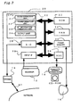
- Fig. 2 is a block diagram illustrating the hardware structure of a digital watermark embedding apparatus 10 that implements the method of embedding the digital watermark in the embodiment.
- the digital watermark embedding apparatus 10 includes a computer 20 and a scanner 12, an external storage device 14, such as CD-ROMs, a modem 16, and a display monitor 18 that are all connected to the computer 20.
- the computer 20 includes a CPU 22 that executes processing, a ROM 23 that stores a monitor program and other programs therein, and a RAM 24 onto which programs are loaded or in which data are temporarily registered in the course of operations.
- the computer 20 also includes a frame memory 25 that functions to display images on the monitor 18, a controller (HDC) 26 that is in charge of data transmission to and from the external storage device 14, a serial input-output circuit (SIO) 28 that is in charge of data transmission to and from the modem 16, and an input interface (input IF) 29 that functions to input images read by the scanner 12.
- a keyboard and a mouse are also connected to the computer 20, although they are omitted from the illustration.
- the modem 16 is connected to a computer network via a communication line NT.
- the computer 20 may download various image processing programs from a non-illustrated server on the computer network via the modem 16.
- the computer 20 may distribute image data with a digital watermark embedded therein through the computer network.
- the CPU 22 executes the programs loaded onto the RAM 24 to realise the functions of a block extraction unit 31, a transformation unit 32, a bit information embedding unit 33, and an output unit 34. These unit respectively correspond to the block extraction means, the transformation means, the bit information embedding means, and the output means of the present invention. The detailed functions of these units will be discussed later as a series of processing executed by the CPU 22.
- Fig. 3 is a flowchart showing a watermark pattern generation routine.
- the CPU first inputs copyright information and extends the input copyright information to decimal digits (step S50).
- the copyright information is used to identify the copyright holder of a master image, which is the object of digital watermarking.
- information corresponding to one code is assigned to each copyright holder.
- One code may alternatively be assigned to each work.
- the process of extending decimal digits intrinsic to each copyright holder may automatically be carried out in the computer 20.
- the copyright holder may manually specify a desired code.
- One preferable procedure transmits required information to a total management center, for example, a copyright management center, via the modem 16 in response to input of a copyright holder name into the computer 20 and receives the code intrinsic to the copyright holder or a work of the copyright holder from the total management center. This allows total management of copyright holder information.
- the CPU then generates a basic pattern, based on the decimal digits (step S60).
- the technique of this embodiment does not simply embed a digital watermark as bit information but embeds the digital watermark in a specific pattern.
- the concrete procedure of this embodiment adopts the density pattern method (more specifically the method of Nakamura, see, e.g., Tanaka et al., Embedding Secret Information into a Dithered Multilevel Image, Proc. 1990 IEEE Military Communications Conf., pp.
- the basic pattern is generated by the following method.
- the signals s(u) are binary data taking either the value '0' or the value '1'.
- the first term on the right side of Equation (1) represents the total number of arrays satisfying s(0) ⁇ 1
- the second term represents the total number of arrays satisfying s(0) ⁇ 0.
- the result of the comparison between copyright management information t (decimal digits) and n2-1 ⁇ m-1 is specified as: when t ⁇ n ⁇ 2 - 1 ⁇ ⁇ m - 1 , s u ⁇ 1 ; and when t ⁇ n ⁇ 2 - 1 ⁇ ⁇ m - 1 , s u ⁇ 0.
- Fig. 5 shows a variety of basic patterns S expressible by the above procedure.
- m is in a range of 7 to 9
- one basic pattern is capable of expressing integers t in decimal notation corresponding to 13 bits.
- the high redundancy may be utilized to implement another series of processing, such as detection of errors.
- the setting for the layout of on (black) bits has a high degree of freedom. Under the condition of a fixed density, one possible application may restrict the number of on (black) pixels among all the pixels in each raster line (that is, the total number of pixels in the direction x) to even numbers.
- Another application may select an appropriate density pattern by taking into account the effects on the picture quality.
- the procedure of this embodiment uses the density pattern having the specific size to allow expression of decimal digits. Only one basic pattern is sufficient when the value t is in the expressible range of the redundancy system 'm-out-of-n2'. In the case where the copyright information, which is the object of management, exceeds this expressible range, the basic pattern may be modified to two or three different layouts, prior to embedding.
- the density pattern is capable of expressing decimal digits, so that the processing of step S60 shown in Fig. 3 selects and generates one of the basic patterns corresponding to the decimal digits obtained at step S50.
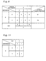
- the CPU repeats the selected basic pattern over the whole range of the image to generate the watermark pattern (step S70). The processing of this step is carried out as discussed below.
- a master image P in which the watermark pattern is to be embedded, consists of 256 pixels ⁇ 256 pixels.
- each pair of adjoining blocks Bu and Bu+1 among all the blocks is specified as one set, there are 32x16 sets.
- Each bit of s(u) is mapped to each set, and the master image P accordingly has 8x4 spaces, each accepting the 4x4 basic pattern.
- the watermark information S can be recorded iteratively by the total of 32 times, that is, four times in the horizontal direction and eight times in the vertical direction, in the master image P.
- the arrangement of recording the basic pattern iteratively to generate the watermark pattern enhances the redundancy of the watermark pattern and attains the sufficiently high resistance against Laplacian attacks on the image data with the digital watermark embedded therein and partial clipping of the image data.
- the two or more basic patterns S are generated by varying the value m to be distinguishable from each other. Since there is a possibility that part of the image is clipped, it is preferable that the plurality of basic patterns S are laid out at random in the 8x4 spaces. This application enables not only the decimal digits but a letter or a series of letters to be embedded. In the case of a large image, the procedure may increase the number of repetitions of the basic pattern and embeds detailed letter information representing the copyright management information.
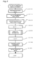
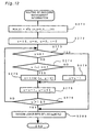
- Fig. 6 is a flowchart showing the outline of a routine of embedding the digital watermark.
- the CPU first reads master image data (step S100), and then carries out color conversion of the input master image data (step S110).
- the color conversion converts the RGB signal system, which is typically used for the image processing on the computer 20, into the YCrCb color difference signal system.
- the master image is expressed by color signals, the color conversion gives image data divided into three planes, that is, a luminance signal Y and color difference signals Cr and Cb.
- the CPU subsequently extracts blocks of 8x8 pixels from the Y plane corresponding to the luminance signal (step S120).
- the procedure sequentially extracts 32 blocks in the horizontal direction x from the upper left corner of the master image as the origin, shifts in the vertical direction y when reaching the end of the horizontal line, and again extracts 32 blocks on a next horizontal line. This series of operations is repeated 32 times to extract 32x32 blocks from the master image.
- Each extracted block in the Y plane is subjected to discrete cosine transform (DCT).
- DCT discrete cosine transform
- the details of the DCT are known in the art and are thus not specifically describedhere.
- the procedure of this embodiment uses a quantization table for the luminance component of JPEG to quantize the DCT coefficients.
- the CPU then embeds the bit information specified according to the preset watermark basic pattern in the DCT coefficients of each block (step S150). The details of this process will be discussed later with reference to Fig. 7 .
- the CPU carries out inverse discrete cosine transform (IDCT) of the 32x32 blocks (step S170), performs reverse color conversion to reconvert the image data into the original RGB system (step S180), and outputs the resulting image (step S190).
- the output may print the image with a color printer or distribute the image to the users on the network via the modem 16.
- the procedure of this embodiment reconverts the image with the embedded watermark pattern into the RGB system, the compressed image in the JPEG format may alternatively be output.
- step S150 The details of the bit information embedding process (step S150) are discussed below.
- the CPU first inputs DCT coefficients Di(u,v) and Di+1(u,v) with regard to u-th and (u+1)-th blocks adjoining to each other in the Y plane (step S151).
- the CPU then divides and quantizes the input DCT coefficients with a quantization table, specifies a frequency coefficient domain F, and identifies elements fu(i,j) and fu+1(i,j) of the frequency coefficient domain F (step S152).
- i, j 0, 1, ... . , 7.
- the CPU calculates an absolute value d(i,j) of the difference between the coefficients at the identical address (i,j) (step S153).
- the CPU subsequently specifies key information K (step S154).
- i, j 0, 1, 2, ..., 7 ⁇ . Inthisembodimentk(i,j) takes either the value '0' or the value '1'.
- the CPU extracts bit information s(u), which is to be embedded, from the watermark pattern S (step S155).
- bit information s(u) is mapped to each pair of adjoining blocks.
- the setting based on the watermark pattern discussed previously maps each piece of bit information to each set of adjoining blocks.
- the CPU then calculates a logic variable D (step S156).
- the setting of the logic variable D is specified according to the following condition. When d(i,j) is not less than a value 'a', D is set equal to 1. When d(i,j) is less than the value 'a', on the other hand, D is set equal to 0.
- the value 'a' represents the resistance of digital watermark. The greater value 'a' generally gives the higher resistance of the digital watermark against an external attack. The extremely large value 'a', however, adversely affects the picture quality.
- the above series of processing identifies the logic variable D based on the absolute value of the difference between the quantized DCT coefficients, the key information K, and the bit information s(u) to be embedded, with regard to a set of adjoining blocks.
- the CPU subsequently calculates an output logic function E1 from these three pieces of information (step S161).
- the symbol ' ⁇ ' shows that a preceding variable is negative logic.
- the CPU determines whether or not the output logic function E1 is equal to 1 (step S162). When E1 is not equal to 1, the next step is skipped. When E1 is equal to 1, on the other hand, the CPU adds a preset value e(i,j) to the greater one of the coefficients fu(i,j) and fu+1(i,j) at step S163.
- the preset value e(i,j) is generally set equal to the value 'a' representing the resistance of the digital watermark.
- the CPU subsequently calculates an output logic function E2 (step S165).
- the CPU determines whether or not the output logic function E2 is equal to 1 (step S166), as in the case of the output logic function E1.
- E2 is equal to 1
- the CPU subtracts the preset value e(i,j) from the greater one of the coefficients fu(i,j) and fu+1(i,j) at step S167.
- the CPU determines whether the above series of processing has been performed for all the blocks included in the master image (step S169), and repeats the above series of processing until the processing has been concluded for all the blocks.
- the master image consisting of 256x256 pixels
- the above series of processing is repeated 32x16 times.
- the 4x4 basic pattern is thus iteratively embedded 4x8 times, as mentioned previously.
- the technique of this embodiment utilizes the quantized DCT (discrete cosine transform) coefficients of the two blocks having a predetermined relationship (the contiguity in the x direction in this embodiment).
- the procedure embeds the bit information s(u) in the coefficients with referring to the key information K.
- this method regards the one-bit watermark signal s(u) as the value of the difference between the pair of elements fu(i,j) and fu+1(i,j) in the frequency coefficient domain and embeds the watermark signal s(u) with the redundancy in the quantized coefficients with regard to each set of the two blocks.
- the watermark pattern is constructed as repetition of the basic pattern. This attains the dual structure of the watermark information and allows introduction of rich redundancy.
- the digital watermark accordingly has sufficiently high resistance against clipping and Laplacian attacks.
- the setting of the resistance may be specified readily by the preset value e(i,j). The resistance against an attack is discussed later as an experiment.
- the image is affected by a minute variation in frequency component over the whole frequency range and slightly deteriorates its picture quality.
- the bit information is still embedded in most of the blocks. The digital watermark can thus be restored with sufficient accuracy.
- the procedure of this embodiment uses the key information K to make the embedding rule closed to the public. This makes it practically impossible for any third person who gains the image to illegally extract and destroy the embedded information.
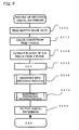
- Fig. 9 is a flowchart showing a routine of decoding a digital watermark.
- Fig. 10 is a flowchart showing the details of the process of decoding embedded bits. These flowcharts correspond to the flowcharts of the digital watermark embedding process shown in Figs. 6 and 7 and are explained briefly.
- the CPU When the program enters the digital watermark decoding routine, the CPU first reads image data, which is the object of decoding the digital watermark (step S200), and carries out color conversion of the input image data (step S210). The CPU then extracts blocks of 8x8 pixels from the Y plane (step S220) and processes the extracted blocks by discrete cosine transform (DCT) (step S230). The CPU decodes embedded bits from the quantized DCT coefficients thus obtained (step S250) and restores a basic pattern of the digital watermark based on the decoded bit information (step S270). The CPU finally outputs a restored digital watermark (step S290).
- image data which is the object of decoding the digital watermark
- step S210 the object of decoding the digital watermark
- the CPU then extracts blocks of 8x8 pixels from the Y plane (step S220) and processes the extracted blocks by discrete cosine transform (DCT) (step S230).
- DCT discrete cosine transform
- the CPU decodes embedded
- the process of decoding the embedded bits at step S250 first inputs DCT coefficients D'i (u,v) and D'i+1 (U,v) of adjoining blocks in the Y plane (step S251).
- the CPU divides and quantizes the DCT coefficients with a quantization table, specifies a frequency coefficient domain F', and identifies elements f'u(i,j) and f'u+1(i,j) of the frequency coefficient domain F' (step S252).
- the CPU subsequently calculates an absolute value d'(i,j) of the difference between the coefficients at the identical address (i,j) (step S253).
- the CPU then specifies the key information K (step S254) and calculates a logic variable D from the absolute value d'(i,j) (step S256).
- the setting of the logic variable D is specified according to the following condition. When d'(i,j) is not less than the value 'a', D is set equal to 1. When d'(i,j) is less than the value 'a', D is set equal to 0.
- the above series of processing identifies the logic variable D based on the absolute value of the difference between the quantized DCT coefficients and the key information K with regard to a set of two blocks.
- the CPU then calculates an output logic function EE from these two pieces of information (step S261).
- the CPU determines whether or not the output logic function EE is equal to 1 (step S262). When EE is equal to 1, a variable g is incremented by one (step S263). When EE is not equal to 1, on the other hand, a variable z is incremented by one (step S264).
- the CPU determines whether the above series of processing has been performed for all the blocks included in the master image (step S266), and repeats the above series of processing until the processing has been concluded for all the blocks.
- the CPU compares the variable g with the variable z and sets either the value '1' or the value '0' to the bit information s(u) embedded in the two blocks according to the majority rule (steps S268 and S269).
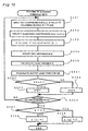
- Fig. 12 is a flowchart showing a routine of decoding copyright management information.
- the CPU first uses variables x and y, which may take values in a range of 1 to 16, and substitutes a number of combinations x ⁇ y of the variables x and y into an array M(x,y) (step S271).
- the CPU then initializes the values x, y, u, and t (step S272), prior to a series of processing discussed below.
- step S273 it is determined whether or not the variable y, which is initialized to the value m, is equal to 0. This determines conclusion of the retrieval. Immediately after a start of this routine, the value of the variable y is not equal to 0.
- the program accordingly proceeds to step S274, at which it is determined whether or not the bit information s(u) is equal to 0.
- bit information s(u) is equal to 0
- an array M(x,y-1) is added to the decimal digits corresponding to the copyright management information (step S275).
- step S276 the variable y is decremented by one. In either case, the variable x is decremented by one while the variable u is incremented by one (step S278).
- the CPU subsequently determines whether or not the variable u exceeds the value '15' (step S279).
- the program shifts to step S280 to decode the lower bits of the management information t as log 2 M(16,j).
- the above series of processing decodes the numerical data, that is, the copyright management information t, embedded in the basic pattern of the digital watermark.
- the technique of this embodiment specifies the basic pattern and repeats the basic pattern a plurality of times to embed the digital watermark. This dual structure ensures introduction of rich redundancy and enables the digital watermark to be decoded easily and stably.
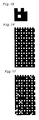
- Fig. 13 shows the basic pattern generated by the method of the embodiment. The generated basic pattern was laid out iteratively in the area of 256x256 at the ratio of one to every two blocks as shown in Fig. 3 . This gave a watermark pattern shown in Fig. 14 .
- This binary image was embedded as the watermark information in the DCT frequency coefficient domain with regard to a variable-density image P. The embedded result is shown in Fig. 15. Fig.
- FIG. 16 shows the result of a Laplacian attack against the resulting image P' with the watermark information embedded therein.
- the watermark information was decoded from the image exposed to the Laplacian attack.
- the decoded result is shown in Fig. 17 .
- the original watermark pattern is mostly preserved through the Laplacian attack. Although part of the watermark pattern was lost, it was easy to accurately restore the original basic pattern from this attacked iterative pattern by utilizing, for example, the principle of majority rule.
- the computer programs that attain the functions of the block extraction unit 31, the transformation unit 32, the bit information embedding unit 33, and the output unit 34 are provided in a specific form recorded in a computer readable recording medium, such as flexible disks or CD-ROMs.
- the computer reads the computer programs from the recording medium and transfers the computer programs to either an internal storage device or an external storage device. Alternatively the computer programs may be supplied to the computer via the communication path.
- a microprocessor included in the computer executes the computer programs stored in the internal storage device to attain the functions specified by the computer programs.
- the computer reads the computer programs recorded in the recording medium and directly executes the computer programs.
- the term 'computer' expresses the concept including a hardware device and an operating system and thus represents the hardware device working under the control of the operating system.
- the hardware device itself is equivalent to the computer.
- the hardware device includes at least a microprocessor like a CPU and means for reading the computer programs recorded in the recording medium.
- the computer programs include program codes that cause the computer to attain the functions of the respective units discussed previously. Part of the functions may be attained not by the application software but by the operating system.
- the programs for carrying out the digital watermark embedding process and the digital watermark decoding process may be added to image processing software in the form of plug-in software programs.
- Typical examples of the 'recording medium' adopted in the present invention include flexible disks, CD-ROMs, magneto-optic discs, IC cards, ROM cartridges, punched cards, prints with barcodes or other codes printed thereon, internal storage devices (memories like a RAM and a ROM) and external storage devices of the computer, and a variety of other computer readable media.
- the technique of the present invention is applicable for apparatuses of embedding watermark information in electronic data and apparatuses of electronic identification.
- the technique is effectively applied for embedding copyright information and for cryptography that includes apparatuses and methods of encryption, transmission, and decryption.
Landscapes
- Engineering & Computer Science (AREA)
- Multimedia (AREA)
- Signal Processing (AREA)
- Physics & Mathematics (AREA)
- General Physics & Mathematics (AREA)
- Theoretical Computer Science (AREA)
- Editing Of Facsimile Originals (AREA)
- Image Processing (AREA)
- Compression Or Coding Systems Of Tv Signals (AREA)
Applications Claiming Priority (3)
| Application Number | Priority Date | Filing Date | Title |
|---|---|---|---|
| JP1567499 | 1999-01-25 | ||
| JP01567499A JP3942759B2 (ja) | 1999-01-25 | 1999-01-25 | 電子透かしの埋め込み方法,復号方法およびその装置 |
| PCT/JP2000/000334 WO2000044163A1 (en) | 1999-01-25 | 2000-01-24 | Method for embedding electronic watermark, decoding method, and devices for the same |
Publications (3)
| Publication Number | Publication Date |
|---|---|
| EP1156662A1 EP1156662A1 (en) | 2001-11-21 |
| EP1156662A4 EP1156662A4 (en) | 2003-04-02 |
| EP1156662B1 true EP1156662B1 (en) | 2009-06-03 |
Family
ID=11895307
Family Applications (1)
| Application Number | Title | Priority Date | Filing Date |
|---|---|---|---|
| EP00900903A Expired - Lifetime EP1156662B1 (en) | 1999-01-25 | 2000-01-24 | Method for embedding electronic watermark, decoding method, and devices for the same |
Country Status (7)
Cited By (2)
| Publication number | Priority date | Publication date | Assignee | Title |
|---|---|---|---|---|
| US8027507B2 (en) | 1998-09-25 | 2011-09-27 | Digimarc Corporation | Method and apparatus for embedding auxiliary information within original data |
| US8959352B2 (en) | 1998-09-25 | 2015-02-17 | Digimarc Corporation | Transmarking of multimedia signals |
Families Citing this family (21)
| Publication number | Priority date | Publication date | Assignee | Title |
|---|---|---|---|---|
| US6522770B1 (en) | 1999-05-19 | 2003-02-18 | Digimarc Corporation | Management of documents and other objects using optical devices |
| US9630443B2 (en) | 1995-07-27 | 2017-04-25 | Digimarc Corporation | Printer driver separately applying watermark and information |
| US6704431B1 (en) * | 1998-09-04 | 2004-03-09 | Nippon Telegraph And Telephone Corporation | Method and apparatus for digital watermarking |
| US7197156B1 (en) | 1998-09-25 | 2007-03-27 | Digimarc Corporation | Method and apparatus for embedding auxiliary information within original data |
| US7142691B2 (en) | 2000-03-18 | 2006-11-28 | Digimarc Corporation | Watermark embedding functions in rendering description files |
| US6952485B1 (en) | 2000-09-11 | 2005-10-04 | Digimarc Corporation | Watermark encoding and decoding in imaging devices and imaging device interfaces |
| US6899475B2 (en) | 2002-01-30 | 2005-05-31 | Digimarc Corporation | Watermarking a page description language file |
| AU2003253184A1 (en) * | 2002-08-28 | 2004-03-19 | Koninklijke Philips Electronics N.V. | Method and arrangement for watermark detection |
| JP3784781B2 (ja) | 2003-05-20 | 2006-06-14 | 富士通株式会社 | 画像データ処理装置、画像データ処理方法、画像データ処理プログラムおよび画像データ処理システム |
| JP3943073B2 (ja) * | 2003-11-28 | 2007-07-11 | 富士通株式会社 | 画像データ処理装置、画像データ処理方法および画像データ処理プログラム |
| DE602005008185D1 (de) * | 2005-01-21 | 2008-08-28 | Unltd Media Gmbh | Verfahren zur Einbettung eines digitalen Wasserzeichens in ein Nutzsignal |
| JP2006319949A (ja) | 2005-04-11 | 2006-11-24 | Toshiba Tec Corp | 非可逆圧縮画像に対する電子透かし作成装置、電子透かし作成プログラム及び電子透かし作成方法 |
| JP2006330256A (ja) * | 2005-05-25 | 2006-12-07 | Kddi Corp | オーディオ信号に対する電子透かし埋込み方法および検出方法 |
| JP4088300B2 (ja) * | 2005-06-01 | 2008-05-21 | 富士通株式会社 | 画像領域検出装置、画像領域検出方法および画像領域検出プログラム |
| JP4804985B2 (ja) * | 2006-03-30 | 2011-11-02 | 株式会社日立製作所 | 生体認証データ生成方法、生体認証データ生成装置、生体認証データプログラム、および個人認証方法。 |
| JP4751786B2 (ja) * | 2006-08-03 | 2011-08-17 | 富士通株式会社 | デコード装置、デコード方法、及びデコードプログラム |
| US8149451B2 (en) | 2007-07-18 | 2012-04-03 | Ricoh Company, Ltd. | Information processing device, information embedding method, and program |
| JP2010041710A (ja) | 2008-07-11 | 2010-02-18 | Ricoh Co Ltd | 埋込情報検出装置、埋込情報検出方法、プログラムおよび記録媒体 |
| CN111640051B (zh) * | 2019-03-01 | 2023-07-25 | 浙江大学 | 一种图像处理方法及其装置 |
| CN112040337B (zh) * | 2020-09-01 | 2022-04-15 | 腾讯科技(深圳)有限公司 | 视频的水印添加和提取方法、装置、设备及存储介质 |
| US12192215B2 (en) * | 2022-09-07 | 2025-01-07 | Xerox Corporation | Method and architecture for providing integrated design of cyber-physical system with watermarking |
Family Cites Families (21)
| Publication number | Priority date | Publication date | Assignee | Title |
|---|---|---|---|---|
| US5721788A (en) * | 1992-07-31 | 1998-02-24 | Corbis Corporation | Method and system for digital image signatures |
| US6122403A (en) * | 1995-07-27 | 2000-09-19 | Digimarc Corporation | Computer system linked by using information in data objects |
| US5778102A (en) * | 1995-05-17 | 1998-07-07 | The Regents Of The University Of California, Office Of Technology Transfer | Compression embedding |
| US5822432A (en) * | 1996-01-17 | 1998-10-13 | The Dice Company | Method for human-assisted random key generation and application for digital watermark system |
| JPH09301916A (ja) | 1996-05-14 | 1997-11-25 | Hoechst Japan Ltd | ポリヒドロキシフェノール誘導体およびそれらからなる骨・軟骨疾患予防・治療剤 |
| US5825892A (en) * | 1996-10-28 | 1998-10-20 | International Business Machines Corporation | Protecting images with an image watermark |
| US5915027A (en) * | 1996-11-05 | 1999-06-22 | Nec Research Institute | Digital watermarking |
| JP3686741B2 (ja) | 1997-02-19 | 2005-08-24 | 富士通株式会社 | 画像データへの識別情報埋め込み方法,識別情報が埋め込まれた画像データからの識別情報抽出方法,画像データへの識別情報埋め込み装置,識別情報が埋め込まれた画像データからの識別情報抽出装置,及びコンピュータ可読媒体 |
| AUPO521897A0 (en) * | 1997-02-20 | 1997-04-11 | Telstra R & D Management Pty Ltd | Invisible digital watermarks |
| EP0860997B1 (en) * | 1997-02-24 | 2008-12-10 | Nec Corporation | Digital data encode system |
| KR19980086811A (ko) * | 1997-05-08 | 1998-12-05 | 니시무로 타이조 | 부가정보 매입과 재생을 위한 장치와 방법 및 그 기록 매체 |
| US5960081A (en) * | 1997-06-05 | 1999-09-28 | Cray Research, Inc. | Embedding a digital signature in a video sequence |
| US7154560B1 (en) * | 1997-10-27 | 2006-12-26 | Shih-Fu Chang | Watermarking of digital image data |
| JPH11196262A (ja) * | 1997-11-07 | 1999-07-21 | Matsushita Electric Ind Co Ltd | デジタル情報埋込み・抽出装置および方法並びに当該方法を実行するためのプログラムを記録した媒体 |
| US6037984A (en) * | 1997-12-24 | 2000-03-14 | Sarnoff Corporation | Method and apparatus for embedding a watermark into a digital image or image sequence |
| US6064764A (en) * | 1998-03-30 | 2000-05-16 | Seiko Epson Corporation | Fragile watermarks for detecting tampering in images |
| US6154571A (en) * | 1998-06-24 | 2000-11-28 | Nec Research Institute, Inc. | Robust digital watermarking |
| KR100294890B1 (ko) * | 1998-07-01 | 2001-07-12 | 윤종용 | 워터마킹을 사용한 디지털 영상 코딩 장치와 디코딩 장치 및 그 방법 |
| US6463162B1 (en) * | 1998-09-30 | 2002-10-08 | Hewlett-Packard Company | Robust watermarking for digital objects |
| US6285775B1 (en) * | 1998-10-01 | 2001-09-04 | The Trustees Of The University Of Princeton | Watermarking scheme for image authentication |
| US6532541B1 (en) * | 1999-01-22 | 2003-03-11 | The Trustees Of Columbia University In The City Of New York | Method and apparatus for image authentication |
-
1999
- 1999-01-25 JP JP01567499A patent/JP3942759B2/ja not_active Expired - Fee Related
-
2000
- 2000-01-24 AU AU30774/00A patent/AU3077400A/en not_active Abandoned
- 2000-01-24 KR KR1020017009178A patent/KR100632901B1/ko not_active Expired - Fee Related
- 2000-01-24 WO PCT/JP2000/000334 patent/WO2000044163A1/ja active IP Right Grant
- 2000-01-24 US US09/889,913 patent/US7523311B1/en not_active Expired - Fee Related
- 2000-01-24 EP EP00900903A patent/EP1156662B1/en not_active Expired - Lifetime
- 2000-01-24 DE DE60042319T patent/DE60042319D1/de not_active Expired - Lifetime
Cited By (3)
| Publication number | Priority date | Publication date | Assignee | Title |
|---|---|---|---|---|
| US8027507B2 (en) | 1998-09-25 | 2011-09-27 | Digimarc Corporation | Method and apparatus for embedding auxiliary information within original data |
| US8611589B2 (en) | 1998-09-25 | 2013-12-17 | Digimarc Corporation | Method and apparatus for embedding auxiliary information within original data |
| US8959352B2 (en) | 1998-09-25 | 2015-02-17 | Digimarc Corporation | Transmarking of multimedia signals |
Also Published As
| Publication number | Publication date |
|---|---|
| WO2000044163A1 (en) | 2000-07-27 |
| JP2000216983A (ja) | 2000-08-04 |
| KR100632901B1 (ko) | 2006-10-11 |
| DE60042319D1 (de) | 2009-07-16 |
| US7523311B1 (en) | 2009-04-21 |
| KR20010102986A (ko) | 2001-11-17 |
| EP1156662A1 (en) | 2001-11-21 |
| EP1156662A4 (en) | 2003-04-02 |
| AU3077400A (en) | 2000-08-07 |
| JP3942759B2 (ja) | 2007-07-11 |
Similar Documents
| Publication | Publication Date | Title |
|---|---|---|
| EP1156662B1 (en) | Method for embedding electronic watermark, decoding method, and devices for the same | |
| JP3860042B2 (ja) | 画像検証装置 | |
| Aslantas | An optimal robust digital image watermarking based on SVD using differential evolution algorithm | |
| US7536026B2 (en) | Image processing apparatus and method | |
| JP3937841B2 (ja) | 情報処理装置及びその制御方法 | |
| Fard et al. | A new genetic algorithm approach for secure JPEG steganography | |
| Shih et al. | Enhancement of image watermark retrieval based on genetic algorithms | |
| Cheung et al. | A sequential quantization strategy for data embedding and integrity verification | |
| Baba et al. | Watermarking of digital images in frequency domain | |
| Singh | A survey on image steganography techniques | |
| Kuribayashi et al. | Robust and secure data hiding for PDF text document | |
| JP2000350007A (ja) | 電子透かし方法、電子透かし装置および記録媒体 | |
| Subhedar | Image steganography using ridgelet transform and svd | |
| Rabie et al. | High-Fidelity Steganography: A Covert Parity Bit Model-Based Approach. | |
| JP3943573B2 (ja) | 電子透かしのための画像処理方法及び装置 | |
| Karim et al. | Image Steganography System Using Bezier Curve | |
| Huang et al. | A novel block-based authentication technique for binary images by block pixel rearrangements | |
| KR20040012272A (ko) | 디지털 영상 인증을 위한 디지털 워터마크의 삽입 및추출방법 | |
| Patel et al. | A literature review on image quality and embedding payload for image steganography | |
| Mansour et al. | Steganographic Method For Reserving Hidden Information Based On Edge Extraction Operators | |
| JP2000165652A (ja) | データ出力制御装置、データ処理装置及びコンピュータ読み取り可能な記憶媒体 | |
| Sandhu et al. | A New Paradigm for Improved Image Steganography by using Adaptive Number of Dominant Discrete Cosine Transform Coefficients | |
| Ker | Information hiding | |
| Altun et al. | Set theoretic quantization index modulation watermarking | |
| Sheluhin et al. | Image Steganography Technique Using Algebraic Fractals |
Legal Events
| Date | Code | Title | Description |
|---|---|---|---|
| PUAI | Public reference made under article 153(3) epc to a published international application that has entered the european phase |
Free format text: ORIGINAL CODE: 0009012 |
|
| 17P | Request for examination filed |
Effective date: 20010822 |
|
| AK | Designated contracting states |
Kind code of ref document: A1 Designated state(s): AT BE CH CY DE DK ES FI FR GB GR IE IT LI LU MC NL PT SE |
|
| A4 | Supplementary search report drawn up and despatched |
Effective date: 20030213 |
|
| RIC1 | Information provided on ipc code assigned before grant |
Ipc: 7H 04N 1/32 B Ipc: 7G 06T 1/00 A |
|
| 17Q | First examination report despatched |
Effective date: 20031118 |
|
| RBV | Designated contracting states (corrected) |
Designated state(s): DE FR GB IT NL |
|
| GRAP | Despatch of communication of intention to grant a patent |
Free format text: ORIGINAL CODE: EPIDOSNIGR1 |
|
| GRAS | Grant fee paid |
Free format text: ORIGINAL CODE: EPIDOSNIGR3 |
|
| GRAA | (expected) grant |
Free format text: ORIGINAL CODE: 0009210 |
|
| AK | Designated contracting states |
Kind code of ref document: B1 Designated state(s): DE FR GB IT NL |
|
| REG | Reference to a national code |
Ref country code: GB Ref legal event code: FG4D |
|
| REF | Corresponds to: |
Ref document number: 60042319 Country of ref document: DE Date of ref document: 20090716 Kind code of ref document: P |
|
| NLV1 | Nl: lapsed or annulled due to failure to fulfill the requirements of art. 29p and 29m of the patents act | ||
| PG25 | Lapsed in a contracting state [announced via postgrant information from national office to epo] |
Ref country code: NL Free format text: LAPSE BECAUSE OF FAILURE TO SUBMIT A TRANSLATION OF THE DESCRIPTION OR TO PAY THE FEE WITHIN THE PRESCRIBED TIME-LIMIT Effective date: 20090603 |
|
| PLBE | No opposition filed within time limit |
Free format text: ORIGINAL CODE: 0009261 |
|
| STAA | Information on the status of an ep patent application or granted ep patent |
Free format text: STATUS: NO OPPOSITION FILED WITHIN TIME LIMIT |
|
| 26N | No opposition filed |
Effective date: 20100304 |
|
| PG25 | Lapsed in a contracting state [announced via postgrant information from national office to epo] |
Ref country code: IT Free format text: LAPSE BECAUSE OF FAILURE TO SUBMIT A TRANSLATION OF THE DESCRIPTION OR TO PAY THE FEE WITHIN THE PRESCRIBED TIME-LIMIT Effective date: 20090603 |
|
| PGFP | Annual fee paid to national office [announced via postgrant information from national office to epo] |
Ref country code: FR Payment date: 20120202 Year of fee payment: 13 |
|
| PGFP | Annual fee paid to national office [announced via postgrant information from national office to epo] |
Ref country code: DE Payment date: 20120118 Year of fee payment: 13 |
|
| PGFP | Annual fee paid to national office [announced via postgrant information from national office to epo] |
Ref country code: GB Payment date: 20120118 Year of fee payment: 13 |
|
| GBPC | Gb: european patent ceased through non-payment of renewal fee |
Effective date: 20130124 |
|
| REG | Reference to a national code |
Ref country code: FR Ref legal event code: ST Effective date: 20130930 |
|
| PG25 | Lapsed in a contracting state [announced via postgrant information from national office to epo] |
Ref country code: DE Free format text: LAPSE BECAUSE OF NON-PAYMENT OF DUE FEES Effective date: 20130801 |
|
| REG | Reference to a national code |
Ref country code: DE Ref legal event code: R119 Ref document number: 60042319 Country of ref document: DE Effective date: 20130801 |
|
| PG25 | Lapsed in a contracting state [announced via postgrant information from national office to epo] |
Ref country code: FR Free format text: LAPSE BECAUSE OF NON-PAYMENT OF DUE FEES Effective date: 20130131 Ref country code: GB Free format text: LAPSE BECAUSE OF NON-PAYMENT OF DUE FEES Effective date: 20130124 |