EP1156481A2 - Optical disk track jump detection - Google Patents
Optical disk track jump detection Download PDFInfo
- Publication number
- EP1156481A2 EP1156481A2 EP01304311A EP01304311A EP1156481A2 EP 1156481 A2 EP1156481 A2 EP 1156481A2 EP 01304311 A EP01304311 A EP 01304311A EP 01304311 A EP01304311 A EP 01304311A EP 1156481 A2 EP1156481 A2 EP 1156481A2
- Authority
- EP
- European Patent Office
- Prior art keywords
- track
- data
- optical disk
- wobble
- feature
- Prior art date
- Legal status (The legal status is an assumption and is not a legal conclusion. Google has not performed a legal analysis and makes no representation as to the accuracy of the status listed.)
- Withdrawn
Links
Images

Classifications
-
- G—PHYSICS
- G11—INFORMATION STORAGE
- G11B—INFORMATION STORAGE BASED ON RELATIVE MOVEMENT BETWEEN RECORD CARRIER AND TRANSDUCER
- G11B27/00—Editing; Indexing; Addressing; Timing or synchronising; Monitoring; Measuring tape travel
- G11B27/10—Indexing; Addressing; Timing or synchronising; Measuring tape travel
- G11B27/19—Indexing; Addressing; Timing or synchronising; Measuring tape travel by using information detectable on the record carrier
- G11B27/24—Indexing; Addressing; Timing or synchronising; Measuring tape travel by using information detectable on the record carrier by sensing features on the record carrier other than the transducing track ; sensing signals or marks recorded by another method than the main recording
-
- G—PHYSICS
- G11—INFORMATION STORAGE
- G11B—INFORMATION STORAGE BASED ON RELATIVE MOVEMENT BETWEEN RECORD CARRIER AND TRANSDUCER
- G11B7/00—Recording or reproducing by optical means, e.g. recording using a thermal beam of optical radiation by modifying optical properties or the physical structure, reproducing using an optical beam at lower power by sensing optical properties; Record carriers therefor
- G11B7/007—Arrangement of the information on the record carrier, e.g. form of tracks, actual track shape, e.g. wobbled, or cross-section, e.g. v-shaped; Sequential information structures, e.g. sectoring or header formats within a track
-
- G—PHYSICS
- G11—INFORMATION STORAGE
- G11B—INFORMATION STORAGE BASED ON RELATIVE MOVEMENT BETWEEN RECORD CARRIER AND TRANSDUCER
- G11B7/00—Recording or reproducing by optical means, e.g. recording using a thermal beam of optical radiation by modifying optical properties or the physical structure, reproducing using an optical beam at lower power by sensing optical properties; Record carriers therefor
- G11B7/08—Disposition or mounting of heads or light sources relatively to record carriers
- G11B7/09—Disposition or mounting of heads or light sources relatively to record carriers with provision for moving the light beam or focus plane for the purpose of maintaining alignment of the light beam relative to the record carrier during transducing operation, e.g. to compensate for surface irregularities of the latter or for track following
- G11B7/0946—Disposition or mounting of heads or light sources relatively to record carriers with provision for moving the light beam or focus plane for the purpose of maintaining alignment of the light beam relative to the record carrier during transducing operation, e.g. to compensate for surface irregularities of the latter or for track following specially adapted for operation during external perturbations not related to the carrier or servo beam, e.g. vibration
-
- G—PHYSICS
- G11—INFORMATION STORAGE
- G11B—INFORMATION STORAGE BASED ON RELATIVE MOVEMENT BETWEEN RECORD CARRIER AND TRANSDUCER
- G11B2220/00—Record carriers by type
- G11B2220/20—Disc-shaped record carriers
- G11B2220/21—Disc-shaped record carriers characterised in that the disc is of read-only, rewritable, or recordable type
- G11B2220/215—Recordable discs
- G11B2220/216—Rewritable discs
-
- G—PHYSICS
- G11—INFORMATION STORAGE
- G11B—INFORMATION STORAGE BASED ON RELATIVE MOVEMENT BETWEEN RECORD CARRIER AND TRANSDUCER
- G11B2220/00—Record carriers by type
- G11B2220/20—Disc-shaped record carriers
- G11B2220/21—Disc-shaped record carriers characterised in that the disc is of read-only, rewritable, or recordable type
- G11B2220/215—Recordable discs
- G11B2220/218—Write-once discs
-
- G—PHYSICS
- G11—INFORMATION STORAGE
- G11B—INFORMATION STORAGE BASED ON RELATIVE MOVEMENT BETWEEN RECORD CARRIER AND TRANSDUCER
- G11B2220/00—Record carriers by type
- G11B2220/20—Disc-shaped record carriers
- G11B2220/25—Disc-shaped record carriers characterised in that the disc is based on a specific recording technology
- G11B2220/2537—Optical discs
- G11B2220/2545—CDs
-
- G—PHYSICS
- G11—INFORMATION STORAGE
- G11B—INFORMATION STORAGE BASED ON RELATIVE MOVEMENT BETWEEN RECORD CARRIER AND TRANSDUCER
- G11B2220/00—Record carriers by type
- G11B2220/20—Disc-shaped record carriers
- G11B2220/25—Disc-shaped record carriers characterised in that the disc is based on a specific recording technology
- G11B2220/2537—Optical discs
- G11B2220/2562—DVDs [digital versatile discs]; Digital video discs; MMCDs; HDCDs
-
- G—PHYSICS
- G11—INFORMATION STORAGE
- G11B—INFORMATION STORAGE BASED ON RELATIVE MOVEMENT BETWEEN RECORD CARRIER AND TRANSDUCER
- G11B27/00—Editing; Indexing; Addressing; Timing or synchronising; Monitoring; Measuring tape travel
- G11B27/10—Indexing; Addressing; Timing or synchronising; Measuring tape travel
- G11B27/19—Indexing; Addressing; Timing or synchronising; Measuring tape travel by using information detectable on the record carrier
- G11B27/28—Indexing; Addressing; Timing or synchronising; Measuring tape travel by using information detectable on the record carrier by using information signals recorded by the same method as the main recording
- G11B27/30—Indexing; Addressing; Timing or synchronising; Measuring tape travel by using information detectable on the record carrier by using information signals recorded by the same method as the main recording on the same track as the main recording
- G11B27/3027—Indexing; Addressing; Timing or synchronising; Measuring tape travel by using information detectable on the record carrier by using information signals recorded by the same method as the main recording on the same track as the main recording used signal is digitally coded
-
- G—PHYSICS
- G11—INFORMATION STORAGE
- G11B—INFORMATION STORAGE BASED ON RELATIVE MOVEMENT BETWEEN RECORD CARRIER AND TRANSDUCER
- G11B7/00—Recording or reproducing by optical means, e.g. recording using a thermal beam of optical radiation by modifying optical properties or the physical structure, reproducing using an optical beam at lower power by sensing optical properties; Record carriers therefor
- G11B7/007—Arrangement of the information on the record carrier, e.g. form of tracks, actual track shape, e.g. wobbled, or cross-section, e.g. v-shaped; Sequential information structures, e.g. sectoring or header formats within a track
- G11B7/00745—Sectoring or header formats within a track
Definitions
- a method for detecting inadvertent track jumps during reading or writing an optical disk the optical disk being formed with a track having a detectable structure within which data is read or written during use of the optical disk.
- the method includes detecting a feature of the track structure of the optical disk at which data is read from or written to during data reading or writing of the disk.
- the detected feature of the track structure is then compared with an expected track structure feature.
- a potential track jump occurrence is flagged in the event of a negative comparison between the detected track structure feature and the expected track structure feature.
- a system for detecting inadvertent track jumps during reading or writing an optical disk the optical disk being formed with a track having a detectable structure within which data is read or written during use of the optical disk.
- the system includes an optical read/write head capable of detecting a feature of the track structure of the optical disk at which data is read from or written to during data reading or writing of the disk.
- the system further includes an optical disk drive controller coupled to the read/write head, that controls writing and reading of data to and from the optical disk by way of the read/write head.
- the optical disk drive controller compares the detected feature of the track structure with an expected track structure feature, and flags a potential track jump occurrence in the event of a negative comparison between the detected track structure feature and the expected track structure feature.
- the data reading or writing operation with the disk is ceased in the event of a potential track jump being flagged.
- the track structure comprises a track wobble.
- the track structure includes addressing information encoded therein in addressing units, and the optical disk track is arranged in a series of data line segments with the track structure for each data line segment having a synchronization unit and an addressing unit.
- the detected feature of the track structure comprises a wobble encoding structure of the addressing unit for at least one data line segment.
- the addressing unit for example, can be encoded differently for adjacent data line segments.
- the optical disk track is further arranged in a series of data block segments each comprising a series of successive data line segments, wherein the detected feature of the track structure comprises a wobble encoding structure that is different as between each of the adjacent data block segments.
- the wobble encoding structure may comprise at least one inverted wobble for in each data line segment, wherein the position of the at least one inverted wobble is different for data line segments of different data block segments.
- the detected feature of the track structure comprises a timing of the occurrence of the synchronization unit of at least one data line segment.
- the detected feature of the track structure comprises an abrupt and sustained change in track wobble phase.
- an optical disk constructed to enable detection of inadvertent track jumps during reading or writing.
- the optical disk is formed with a pre-groove track having a detectable structure within which data is read or written during use of the optical disk.
- the pre-groove track structure includes addressing information encoded therein in addressing units, with the pre-groove track arranged in a series of data line segments and the track structure for each data line segment having a synchronization unit and an addressing unit.
- the pre-groove track is further arranged in a series of data block segments each comprising a series of successive data line segments.
- the detected feature of the track structure comprises a wobble encoding structure that is different as between each of the adjacent data block segments.
- Using some or all of the techniques of the invention disclosed herein can reduce the probability of a track jump occurring in a manner that is undetectable within a distance too long for ECC recovery. These techniques may be coupled with other processing, such as detecting deviations from the predicted address bits (based on the previous address sequence), to reduce undesirable consequences of inadvertent track jumps.
- data is stored on a typical optical disk having reference to tracks which are formed on the disk during manufacture.
- the spiral track formed on the disk at the time if manufacture is sometimes referred to as a pre-groove.
- the tracks are formed from a single spiral groove, with each track being considered a 360 degree turn of the spiral.
- the track pitch which is the distance between the average track centerlines of adjacent tracks measured in the radial direction, is 0.74 micrometers.
- the tracks are structured so that addressing information can be obtained therefrom, separate to the data which may be associated with the tracks.
- the tracks are formed with a cyclic radial perturbation, which is nominally a sinusoidal deviation from the true spiral path of the track. This track path deviation is referred to as a wobble, and each sinusoidal cycle is called a wobble cycle.
- the addressing information of the optical disk tracks is conveyed by phase modulation of the wobble, which is can be detected and decoded by the disk drive controller.
- ECC error correction code
- FIG. 1 is a conceptual block diagram of an error correction data block for a DVD+RW format.
- the data block as shown contains 32 kilobytes of data organized into 208 lines. Each line comprises two sync frames, wherein each sync frame has a synchronization header followed by data.
- Each sync frame when stored on the disk comprises 1488 channelbits (channelbits are the elements by which, after modulation, the binary values "0" and "1" are represented).
- Addressing information (Address-in-Pregroove or ADIP) is represented by the disk tracks on the basis of one bit of addressing information for each line of stored data.
- Each ADIP word comprises 52 ADIP units, with the first being utilized as an ADIP word synchronization header. Therefore, addressing information is repeated four times over the 208 line span of one 32k EC data block, so that a single ADIP word is distributed along a portion of disk track which holds one quadrant of a data block (8k of stored data).
- the track jump should be detectable by the disk drive controller in less than the amount of time during which it takes to write the largest amount of data which is recoverable by the error correction scheme. In the above example, that is 2k bytes.
- FIG. 2 is a simplified block timing diagram which illustrates the relationship between data stored on a DVD+RW optical disk and the addressing information that is contained in the wobbled track structure thereof.
- One line of data is indicated at 10 in the figure in block diagram form, comprising two sync frames each having a sync header followed by data.
- the length of the optical disk track along which one line of data is stored has 93 wobble cycles, and the wobbled track structure is indicated in the figure at 20 .
- Each wobble corresponds to 32 channelbits of data stored on the track.
- the ADIP addressing information is contained in the first 8 wobble cycles of the track corresponding to each data line 10 .
- the 8 wobble cycles convey one ADIP unit, which is one bit of addressing information.
- ADIP units make up one ADIP word, which is one unit for synchronization and 51 for address.
- the remaining 85 wobble cycles along each data line do not carry addressing information but are utilized by the disk drive controller for timing purposes.
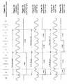
- Figure 3 is a diagrammatic timing diagram illustrating the way in which addressing information is coded into the wobble cycles of the first 8 wobbles of a 93 wobble length of track corresponding to one data line.
- the wobble cycle numbering is shown in Figure 3a, beginning at #92 which is the final wobble cycle from a previous line, followed by cycles #0 to #9 from the line under consideration.
- Figure 3b represents the wobble cycle modulation for the first unit in an ADIP word, which is a special synchronization unit that identifies the beginning of an EC data block quadrant.
- Figure 3c illustrates the demodulated signal for the ADIP word sync.
- the wobble structure and demodulated signal for an ADIP unit representing a binary "0" is shown in Figures 3d and 3e , respectively.
- the wobble structure and demodulated signal for an ADIP unit representing a binary "1" is shown in Figures 3f and 3g .
- the coding of ADIP data in the wobble of the track is achieved by phase modulation of the wobble, by inverting certain wobble cycles in the first eight.
- the wobble of the pre-groove track is nominally sinusoidal with a phase which is herein referred to as a positive wobble (PW) phase.
- PW positive wobble
- the 85 wobbles not used for addressing carry no information then they are all of the same PW phase.
- the first cycle of each ADIP unit (cycle # 0 ) is always an inverted cycle, referred to as a negative wobble or NW.
- cycles #1 to #3 are also inverted, NW, cycles, which indicates the beginning of an EC data block quadrant.
- NW cycles, which indicates the beginning of an EC data block quadrant.
- PW PW cycles.
- the first NW cycle is followed by three PW cycles, and together the first four cycles constitute an ADIP bit sync. Then, the remaining four wobble cycles are used to convey the addressing data, either a binary "0" or a binary "1".
- cycles #4 and #5 are PW phase and cycles #6 and #7 are NW phase.
- cycles #6 and #7 are NW phase.
- Figures 3f and 3g the pattern is reversed, with cycles #4 and #5 of NW phase and cycles #6 and #7 PW phase.
- the remaining 85 wobble cycles (cycles #8 to #92 ) are not allocated for data coding and are nominally all PW phase, as mentioned above.
- ADIP bit units Fifty-two ADIP units are grouped into each ADIP word.
- the information contained in the ADIP bit units is as follows:
- the 52 ADIP bits are grouped into thirteen 4-bit nibbles.
- Five parity nibbles N8 to N12 contain the ADIP bits 32 to 51, which are determined from the nibbles N0 to N7 (containing ADIP bits 0 to 31) according to a nibble-based Reed-Solomon (13,8,6) error correction coding scheme.
- a DVD+RW format optical disk retrieves stored data using edge detection which operates more reliably with limitations on the number of consecutive binary "0"s and "1"s in the recorded channel bits.
- a run length limitation coding scheme is employed, such as an Inverted Binary Extended Hamming (IBEH) code.
- IBEH Inverted Binary Extended Hamming
- Such coding can, for example, convert an 8 bit data word into a 16 bit code word in a predetermined way so that the binary representation of the code word, and any possible concatenation of code words, meets the run length limitations.
- each 8 bit data word can be coded into several different 16 bit code words depending upon the coding state.
- the coding state can be changed from one data word to the next in a predictable way to meet the run length limitations.
- address information is encoded as a phase-modulated high frequency wobbled groove. This address information is available four times per 32k data block and is distributed over each quadrant. However, since a quadrant consists of 8k bytes of data, relying on address detection to detect an inadvertent track jump could result in an overwrite burst error that is too long to be recovered by the ECC. Accordingly, it is desirable to provide at least one scheme for detecting the occurrence of an inadvertent track jump within a time period or disk track length that is within the capability of the error correction scheme.
- a track jump should be detectable within a time period or track length that is less than the time period or track length within which 2k bytes of data can be written following the occurrence of the jump.
- the wobbled pre-groove is used for the track jump detection.
- the wobble cycles of the pre-groove which are not used by the ADIP addressing information can be encoded with additional data which allows reliable track jump detection.
- each line of data corresponds to 93 wobble cycles of the pre-groove, and eight of the wobble cycles are used to represent one ADIP unit per line.
- the additional data for track jump detection can be encoded into the remaining 85 wobbles along the data lines on the disk. It will be appreciated by those skilled in the art, however, that it is preferable to not encode too much information in the wobbled pre-groove track so that decoding of the wobble cycle information is reliable.
- wobble cycle information is represented by inverting certain wobbles
- many wobbles will be inverted and the decoder may have difficulty synchronizing with the pre-groove and/or have difficulty determining which is the positive wobble phase and which is the negative wobble phase.
- One way in which the unused wobbles can be employed for track jump detection is to invert one or more selected wobbles of the 85 unused wobbles along each data line, wherein the wobble(s) that are inverted are different for adjacent tracks.
- at least one of the unused wobbles is inverted in a selected pattern such that, for nearby tracks on the disk, the inverted wobble(s) occurs in a different position along a data line (as compared to the ADIP bit sync). Then, if an inadvertent jump occurs from one track to a nearby track, the disk controller can detect that the position of the inverted wobble has changed in an unpredicted way, which is taken to indicate a possible track jump.
- One possible implementation of this form of the invention involves adding an inverted wobble in the unused portion of each data line, wherein the location of the inverted wobble in relation to the ADIP bit sync is different for successive data blocks.
- a single 32k byte data block extends over a little more than one half of a disk track at the inner circumference of the disk writable area. If all of the 85 unused wobbles were employed for the track jump detection scheme with a single inverted wobble, then the minimum number of tracks which must be jumped for the resulting track to have the same inverted wobble position as the original is about 42. This makes it very unlikely that a track jump could occur wherein the inverted wobble position before and after the jump matches, enabling reliable detection of track jumps. It make be useful for the purposes of easier binary calculations to instead have the inverted wobble position or pattern repeat every 16 or 32 data blocks, which still enables accurate track jump detection.
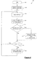
- FIG. 4 is a simple flow chart diagram illustrating an example of a track jump detection procedure 400 based on the above described technique.
- the flow chart procedure 400 beginning at step 402 , relates to writing of data on an optical disk, which is the most critical for track jump detection.
- a track jump detection value y is determined at step 404, for example representing the position of an inverted wobble cycle corresponding to the data block being written.
- the ADIP unit at the beginning of each data line is detected at step 406 .
- the remaining 85 wobble cycles for the line are nominally PW phase cycles.
- the number of PW cycles ( x ) following the ADIP unit are counted (step 408 ) until a NW cycle is detected.
- the NW cycle is the inverted wobble inserted for the purposes of track jump detection (or possibly an unexpected NW cycle of an ADIP unit if a track jump has occurred). If the ADIP unit detected at step 406 indicates the beginning of a new data block (step 410 ), then it is necessary to compute what the track jump detection codey for that block should be.
- the measured cycle count x is compared to the track jump detection code y for the current block to which data is intended to be written. If the parameters x and y match each other, this is taken as an indication that the correct data block is being written to, i.e. the situation is normal. If, on the other hand, the parameters x and y do not match then a possible track jump incident is indicated. In that case, the writing of data is suspended immediately (step 416 ) so that if a track jump has occurred the amount of data written erroneously is minimized. The data writing is suspended until the data address on the disk is verified by the disk controller and the correct track portion located if necessary.
- Another technique which can be employed for track jump detection in accordance with an embodiment of the present invention involves the coding of the dibit which is used in the ADIP units.
- addressing information is conveyed by phase modulation of the pre-groove wobble using the first eight wobble cycles of the track for each data line.
- the first four wobbles of each ADIP unit are used for word or bit synchronization, and the remaining four wobbles are used to represent a single bit of addressing information.
- the four wobble cycles used for addressing information are modulated (as shown in Figure 3 ) as two PW followed by two NW to represent a data "0", and two NW followed by two PW to represent a data "1".
- This coding is sometimes referred to as a dibit. Because four wobble cycles are used to represent one addressing data bit, the inherent redundancy in the coding can be exploited for track jump detection.
- the standard dibit is defined as four cycles with the second pair of opposite polarity to the first pair.
- An alternate version of the dibit would be four cycles with the second and fourth cycles of opposite polarity to the first and third.
- Another dibit coding would be to have the first and fourth cycles of opposite polarity to the second and third.
- the likelihood of successfully detecting a track jump may be only two in three, where the three alternate dibit codings are employed.
- the dibit coding is varied along a sequence of lines in a more complex pattern than simply alternating dibit versions, and more than one data line is examined, the likelihood of successful track jump detection is increased.
- this technique can be combined with other track jump detection techniques disclosed herein to increase track jump detection reliability.
- Another track jump detection technique of the present invention utilizes the ADIP sync wobble cycles.
- the first wobble is always an inverted (NW) cycle.
- NW inverted
- the regular occurrence of this NW cycle every 93 wobbles along the disk track can be used as a form of horizontal flywheel lock.
- the disk controller can expect to detect the NW sync cycle at a predictable interval.
- the likelihood is small that the resulting track position will match the horizontal flywheel lock of the previous track. Therefore, if several data lines in succession are read or written without the NW sync cycle occurring at the time predicted by the disk controller, this may be taken as an indication of a possible track jump.
- the unused wobble cycles along the track which are nominally all of the same phase are used by the disk controller to generate a synchronized clock signal which can then be used to detect the modulated wobbles.
- a track jump occurs it is unlikely that the track wobble at the resulting position will match the phase of the track wobble at the previous position. Therefore, if an abrupt and sustained phase discontinuity in the recovered clock is detected, this may also be taken to indicate the possible occurrence of an unintended track jump.
Landscapes
- Optical Recording Or Reproduction (AREA)
- Signal Processing For Digital Recording And Reproducing (AREA)
- Optical Record Carriers And Manufacture Thereof (AREA)
Abstract
Description
- The present invention relates to the field of track jump detection during reading and/or writing of an optical disk.
- When reading or writing data with an optical disk data recorder drive, such as DVD+RW, there is the possibility of having an inadvertent track jump due to mechanical or other disturbances. An optical disk such as a digital versatile disk (DVD) or compact disk (CD) is typically formatted with tracks formed from a single spiral groove, with each track being considered a 360 degree turn of the spiral. The tracks provide a framework for writing data onto the disk and reading data therefrom. When reading data, for example, a read head is aligned with a desired track of the disk and the data on that track is sensed as the disk rotates past the head. A track jump can be considered as relative displacement of the read/write head from the desired track. Track jumping occurs as a matter of course during operation of an optical disk, to move the read/write head from one disk location to another. Intentional track jumps under control of the disk drive controller typically involve accurate positioning of the read/write head in relation to the disk surface so that the head aligns with another known track at a known time. An unintentional track jump can occur, for example, when a mechanical disturbance of the disk drive causes the read/write head to lose alignment with the desired track of the disk at an unpredictable time and by an unknown radial displacement. Because the timing and displacement from the desired track is unintentional, the disk drive controller can be unaware that the desired track alignment has been lost and the controller may be unable to determine what displacement has occurred in order to correct or compensate for it.
- If data is being written to a disk when an unintentional track jump occurs, this can have the undesired effect of overwriting of data on the disk track to which the read/write head has jumped. Accordingly, it is desirable to provide means by which a track jump can be detected. In particular, it is desirable to be able to detect the occurrence of such a jump in a time sufficiently short that the amount of good data that is unintentionally overwritten is sufficiently small to be recovered by a data error correction scheme.
- Protection against inadvertent track jumps can be particularly relevant in portable data storage/retrieval applications, such as a camcorder, where there may be mechanical noise and frequent deliberate track jumps to avail of variable bit rate recording. In a less critical situation, track jump detection is valuable in portable data reading applications. A possible situation (for illustrative purposes) would be a many-hour long compilation of MP3 music titles, recorded on a (8-cm) DVD+RW disc. Accurate track jump detection in that case can reduce the likelihood of interruptions to the music during playback, and could also reduce the amount of data buffering which is employed between the read head and the output. A player could avail of the wobble addressing information to detect and correct inadvertent track jumps, and this may help compensate for the lower data signal available from phase change discs.
- In accordance with the principles of the present invention, there is provided a method for detecting inadvertent track jumps during reading or writing an optical disk, the optical disk being formed with a track having a detectable structure within which data is read or written during use of the optical disk. The method includes detecting a feature of the track structure of the optical disk at which data is read from or written to during data reading or writing of the disk. The detected feature of the track structure is then compared with an expected track structure feature. Then, a potential track jump occurrence is flagged in the event of a negative comparison between the detected track structure feature and the expected track structure feature.
- In accordance with the present invention there is also provided a system for detecting inadvertent track jumps during reading or writing an optical disk, the optical disk being formed with a track having a detectable structure within which data is read or written during use of the optical disk. The system includes an optical read/write head capable of detecting a feature of the track structure of the optical disk at which data is read from or written to during data reading or writing of the disk. The system further includes an optical disk drive controller coupled to the read/write head, that controls writing and reading of data to and from the optical disk by way of the read/write head. The optical disk drive controller compares the detected feature of the track structure with an expected track structure feature, and flags a potential track jump occurrence in the event of a negative comparison between the detected track structure feature and the expected track structure feature.
- Preferably the data reading or writing operation with the disk is ceased in the event of a potential track jump being flagged.
- In the preferred embodiments of the invention, the track structure comprises a track wobble. In some preferred implementations of the invention, the track structure includes addressing information encoded therein in addressing units, and the optical disk track is arranged in a series of data line segments with the track structure for each data line segment having a synchronization unit and an addressing unit.
- In one particular form of the invention, the detected feature of the track structure comprises a wobble encoding structure of the addressing unit for at least one data line segment. The addressing unit, for example, can be encoded differently for adjacent data line segments.
- In another form of the invention the optical disk track is further arranged in a series of data block segments each comprising a series of successive data line segments, wherein the detected feature of the track structure comprises a wobble encoding structure that is different as between each of the adjacent data block segments. The wobble encoding structure may comprise at least one inverted wobble for in each data line segment, wherein the position of the at least one inverted wobble is different for data line segments of different data block segments.
- In another form of the invention the detected feature of the track structure comprises a timing of the occurrence of the synchronization unit of at least one data line segment.
- In another form of the invention the detected feature of the track structure comprises an abrupt and sustained change in track wobble phase.
- In accordance with the present invention there is further provided an optical disk constructed to enable detection of inadvertent track jumps during reading or writing. The optical disk is formed with a pre-groove track having a detectable structure within which data is read or written during use of the optical disk. The pre-groove track structure includes addressing information encoded therein in addressing units, with the pre-groove track arranged in a series of data line segments and the track structure for each data line segment having a synchronization unit and an addressing unit. The pre-groove track is further arranged in a series of data block segments each comprising a series of successive data line segments. The detected feature of the track structure comprises a wobble encoding structure that is different as between each of the adjacent data block segments. This allows a disk drive controller, in use of the disk, to detect a potential disk track jump by comparing the detected feature of the track structure with a predetermined expected track structure feature, wherein if the two are different occurrence of a potential inadvertent track jump is indicated.
- Using some or all of the techniques of the invention disclosed herein can reduce the probability of a track jump occurring in a manner that is undetectable within a distance too long for ECC recovery. These techniques may be coupled with other processing, such as detecting deviations from the predicted address bits (based on the previous address sequence), to reduce undesirable consequences of inadvertent track jumps.
- The invention is described in greater detail hereinafter, by way of example only, through description of a preferred embodiment thereof and with reference to the accompanying drawings in which:
- Figure 1 is a conceptual diagram of a data block format for a DVD;
- Figure 2 is a block diagram illustrating a relationship between stored data and track addressing information for a DVD;
- Figure 3 is a timing diagram illustrating an addressing information format for a DVD; and
- Figure 4 is a flow chart diagram of an exemplary procedure for track jump detection in accordance with an embodiment of the present invention.
-
- A method and apparatus for track jump detection during reading and/or writing of an optical disk is disclosed herein. In the following description, for purposes of explanation, specific nomenclature and specific implementation details are set forth to provide a thorough understanding of the present invention. However, it will be apparent to one skilled in the art that these specific details are not required in order to practice the present invention. For example, the preferred embodiment is described in the context of DVD+RW disks, but the techniques of the invention are equally applicable to other forms of optical disks.
- As mentioned above, data is stored on a typical optical disk having reference to tracks which are formed on the disk during manufacture. The spiral track formed on the disk at the time if manufacture is sometimes referred to as a pre-groove. In the case of a digital versatile disk (DVD), for example, the tracks are formed from a single spiral groove, with each track being considered a 360 degree turn of the spiral. The track pitch, which is the distance between the average track centerlines of adjacent tracks measured in the radial direction, is 0.74 micrometers.
- In order to enable the disk drive controller to determine which track the read/write head is aligned with, the tracks are structured so that addressing information can be obtained therefrom, separate to the data which may be associated with the tracks. On a DVD the tracks are formed with a cyclic radial perturbation, which is nominally a sinusoidal deviation from the true spiral path of the track. This track path deviation is referred to as a wobble, and each sinusoidal cycle is called a wobble cycle. The addressing information of the optical disk tracks is conveyed by phase modulation of the wobble, which is can be detected and decoded by the disk drive controller.
- In the DVD standard, data is organized into blocks according to an error correction code (ECC) scheme, so that data recovery is possible if data in the block becomes corrupted. An error correction block contains 32k bytes of data and the ECC scheme is capable of recovering a burst error of magnitude a little over 2k bytes. The correspondence between the data which is written on the disk and addressing information encoded in the track wobbles is such that addressing information is available to the disk drive controller four times over the duration of reading or writing one EC data block.
- Figure 1 is a conceptual block diagram of an error correction data block for a DVD+RW format. The data block as shown contains 32 kilobytes of data organized into 208 lines. Each line comprises two sync frames, wherein each sync frame has a synchronization header followed by data. Each sync frame when stored on the disk comprises 1488 channelbits (channelbits are the elements by which, after modulation, the binary values "0" and "1" are represented). Addressing information (Address-in-Pregroove or ADIP) is represented by the disk tracks on the basis of one bit of addressing information for each line of stored data. Each ADIP word comprises 52 ADIP units, with the first being utilized as an ADIP word synchronization header. Therefore, addressing information is repeated four times over the 208 line span of one 32k EC data block, so that a single ADIP word is distributed along a portion of disk track which holds one quadrant of a data block (8k of stored data).
- Using the above described location addressing format, it is apparent that at least 8k of data will pass the read/write head of the optical disk drive in the time required for the controller to ascertain the location address of the head on the disk. Thus, if an unintentional track jump were to occur during a write operation, for example, at least one quadrant of data would be written on an unintended track before the disk drive controller could ascertain the track address and determine that the head is aligned with the wrong track. If that track already contained data which was overwritten following the track jump then at least 8k of that data would be overwritten before the track jump could be detected by observing the ADIP information. This amount of data cannot be recovered using the ECC scheme.
- In view of the foregoing, in order for track jump detection to be most effective, the track jump should be detectable by the disk drive controller in less than the amount of time during which it takes to write the largest amount of data which is recoverable by the error correction scheme. In the above example, that is 2k bytes.
- Figure 2 is a simplified block timing diagram which illustrates the relationship between data stored on a DVD+RW optical disk and the addressing information that is contained in the wobbled track structure thereof. One line of data is indicated at 10 in the figure in block diagram form, comprising two sync frames each having a sync header followed by data. The length of the optical disk track along which one line of data is stored has 93 wobble cycles, and the wobbled track structure is indicated in the figure at 20. Each wobble corresponds to 32 channelbits of data stored on the track. In a proposed DVD+RW standard format the ADIP addressing information is contained in the first 8 wobble cycles of the track corresponding to each
data line 10. The 8 wobble cycles convey one ADIP unit, which is one bit of addressing information. As mentioned 52 ADIP units make up one ADIP word, which is one unit for synchronization and 51 for address. The remaining 85 wobble cycles along each data line do not carry addressing information but are utilized by the disk drive controller for timing purposes. - Figure 3 is a diagrammatic timing diagram illustrating the way in which addressing information is coded into the wobble cycles of the first 8 wobbles of a 93 wobble length of track corresponding to one data line. The wobble cycle numbering is shown in Figure 3a, beginning at #92 which is the final wobble cycle from a previous line, followed by
cycles # 0 to #9 from the line under consideration. Figure 3b represents the wobble cycle modulation for the first unit in an ADIP word, which is a special synchronization unit that identifies the beginning of an EC data block quadrant. Figure 3c illustrates the demodulated signal for the ADIP word sync. The wobble structure and demodulated signal for an ADIP unit representing a binary "0" is shown in Figures 3d and 3e, respectively. Similarly, the wobble structure and demodulated signal for an ADIP unit representing a binary "1" is shown in Figures 3f and 3g. - The coding of ADIP data in the wobble of the track is achieved by phase modulation of the wobble, by inverting certain wobble cycles in the first eight. The wobble of the pre-groove track is nominally sinusoidal with a phase which is herein referred to as a positive wobble (PW) phase. For example, if the 85 wobbles not used for addressing carry no information then they are all of the same PW phase. Referring to Figure 3, it can be seen that the first cycle of each ADIP unit (cycle #0) is always an inverted cycle, referred to as a negative wobble or NW. In the case of an ADIP word sync unit (Figures 3b and 3c) cycles #1 to #3 are also inverted, NW, cycles, which indicates the beginning of an EC data block quadrant. The remaining four cycles of the ADIP word sync unit are PW cycles.
- For the ADIP bit units the first NW cycle is followed by three PW cycles, and together the first four cycles constitute an ADIP bit sync. Then, the remaining four wobble cycles are used to convey the addressing data, either a binary "0" or a binary "1". For a binary "0" (Figures 3d and 3e) cycles #4 and #5 are PW phase and cycles #6 and #7 are NW phase. For a binary "1" (Figures 3f and 3g) the pattern is reversed, with
cycles # 4 and #5 of NW phase and cycles #6 and #7 PW phase. The remaining 85 wobble cycles (cycles # 8 to #92) are not allocated for data coding and are nominally all PW phase, as mentioned above. - Fifty-two ADIP units are grouped into each ADIP word. The information contained in the ADIP bit units is as follows:
- Bit 0:
- this bit contains no valid bit modulation and is used for synchronization. The content is interpreted as binary "0".
- Bit 1:
- this bit is reserved and is set to binary "0".
-
Bits 2 to 23: - these 22 bits contain a physical address.
Data bit 2 is the most significant bit and data bit 23 is the least significant bit. The addresses increase by one for each next ADIP word. - Bits 24 to 31:
- these 8 bits can be used to contain auxiliary information about the disk. For example, bits 24 to 31 from 256 consecutive ADIP words can form one ADIP frame with 256 bytes of physical format information relating to the disk.
- Bits 32 to 51:
- these 20 bits contain error correction parities for the ADIP information.
- For the purposes of ADIP error correction the 52 ADIP bits are grouped into thirteen 4-bit nibbles. Five parity nibbles N8 to N12 contain the ADIP bits 32 to 51, which are determined from the nibbles N0 to N7 (containing
ADIP bits 0 to 31) according to a nibble-based Reed-Solomon (13,8,6) error correction coding scheme. - When data is stored on the optical disk various forms of encoding can be employed, for example to allow the most reliable data recovery during a read operation. A DVD+RW format optical disk retrieves stored data using edge detection which operates more reliably with limitations on the number of consecutive binary "0"s and "1"s in the recorded channel bits. To achieve the desired limitations, a run length limitation coding scheme is employed, such as an Inverted Binary Extended Hamming (IBEH) code. Such coding can, for example, convert an 8 bit data word into a 16 bit code word in a predetermined way so that the binary representation of the code word, and any possible concatenation of code words, meets the run length limitations. Various different coding "states" can be used to achieve the run length limitations, wherein each 8 bit data word can be coded into several different 16 bit code words depending upon the coding state. The coding state can be changed from one data word to the next in a predictable way to meet the run length limitations.
- Having described the format of an optical disk storage system using the DVD+RW as an example, it is easier to describe the track jump detection schemes according to embodiments of the invention, several of which are explained below as examples.
- In the DVD+RW re-writable format, address information is encoded as a phase-modulated high frequency wobbled groove. This address information is available four times per 32k data block and is distributed over each quadrant. However, since a quadrant consists of 8k bytes of data, relying on address detection to detect an inadvertent track jump could result in an overwrite burst error that is too long to be recovered by the ECC. Accordingly, it is desirable to provide at least one scheme for detecting the occurrence of an inadvertent track jump within a time period or disk track length that is within the capability of the error correction scheme. In the case of the DVD+RW format, a track jump should be detectable within a time period or track length that is less than the time period or track length within which 2k bytes of data can be written following the occurrence of the jump. In the preferred forms of the invention, the wobbled pre-groove is used for the track jump detection.
- In a first form of the invention, the wobble cycles of the pre-groove which are not used by the ADIP addressing information can be encoded with additional data which allows reliable track jump detection. As described in relation to Figures 1 and 2, each line of data corresponds to 93 wobble cycles of the pre-groove, and eight of the wobble cycles are used to represent one ADIP unit per line. Thus, the additional data for track jump detection can be encoded into the remaining 85 wobbles along the data lines on the disk. It will be appreciated by those skilled in the art, however, that it is preferable to not encode too much information in the wobbled pre-groove track so that decoding of the wobble cycle information is reliable. For example, because wobble cycle information is represented by inverting certain wobbles, if a large amount of information is encoded then many wobbles will be inverted and the decoder may have difficulty synchronizing with the pre-groove and/or have difficulty determining which is the positive wobble phase and which is the negative wobble phase.
- One way in which the unused wobbles can be employed for track jump detection is to invert one or more selected wobbles of the 85 unused wobbles along each data line, wherein the wobble(s) that are inverted are different for adjacent tracks. In other words, at least one of the unused wobbles is inverted in a selected pattern such that, for nearby tracks on the disk, the inverted wobble(s) occurs in a different position along a data line (as compared to the ADIP bit sync). Then, if an inadvertent jump occurs from one track to a nearby track, the disk controller can detect that the position of the inverted wobble has changed in an unpredicted way, which is taken to indicate a possible track jump.
- One possible implementation of this form of the invention involves adding an inverted wobble in the unused portion of each data line, wherein the location of the inverted wobble in relation to the ADIP bit sync is different for successive data blocks. A single 32k byte data block extends over a little more than one half of a disk track at the inner circumference of the disk writable area. If all of the 85 unused wobbles were employed for the track jump detection scheme with a single inverted wobble, then the minimum number of tracks which must be jumped for the resulting track to have the same inverted wobble position as the original is about 42. This makes it very unlikely that a track jump could occur wherein the inverted wobble position before and after the jump matches, enabling reliable detection of track jumps. It make be useful for the purposes of easier binary calculations to instead have the inverted wobble position or pattern repeat every 16 or 32 data blocks, which still enables accurate track jump detection.
- Of course it will be recognized by those skilled in the art that this technique is not limited to simply inverting a single wobble of varying position for each data block. Various other patterns of inverted wobbles could alternatively be used employing one or more inverted wobbles, bearing in mind the desirability of leaving the unused wobbles in the same state as much as possible for synchronization of the decoder. It will also be appreciated that it is not necessary that the inverted wobble coding for track jump detection be changed at data block boundaries, although the data blocks represent a convenient unit for that purpose.
- Figure 4 is a simple flow chart diagram illustrating an example of a track
jump detection procedure 400 based on the above described technique. Theflow chart procedure 400, beginning atstep 402, relates to writing of data on an optical disk, which is the most critical for track jump detection. A track jump detection value y is determined atstep 404, for example representing the position of an inverted wobble cycle corresponding to the data block being written. During the data writing procedure, the ADIP unit at the beginning of each data line is detected atstep 406. Following the ADIP unit, the remaining 85 wobble cycles for the line are nominally PW phase cycles. The number of PW cycles (x) following the ADIP unit are counted (step 408) until a NW cycle is detected. The NW cycle is the inverted wobble inserted for the purposes of track jump detection (or possibly an unexpected NW cycle of an ADIP unit if a track jump has occurred). If the ADIP unit detected atstep 406 indicates the beginning of a new data block (step 410), then it is necessary to compute what the track jump detection codey for that block should be. The new track jump detection code is generated atstep 412 according to a predetermined function, e.g. y =f(data block #). In the simplest case it may be that is simply determined from the data block number, modulo 16 or 32, although other functions will be apparent to those skilled in the art. Atstep 414, then, the measured cycle count x is compared to the track jump detection code y for the current block to which data is intended to be written. If the parameters x and y match each other, this is taken as an indication that the correct data block is being written to, i.e. the situation is normal. If, on the other hand, the parameters x and y do not match then a possible track jump incident is indicated. In that case, the writing of data is suspended immediately (step 416) so that if a track jump has occurred the amount of data written erroneously is minimized. The data writing is suspended until the data address on the disk is verified by the disk controller and the correct track portion located if necessary. - Another technique which can be employed for track jump detection in accordance with an embodiment of the present invention involves the coding of the dibit which is used in the ADIP units. As shown in Figure 3 and described hereinabove, addressing information is conveyed by phase modulation of the pre-groove wobble using the first eight wobble cycles of the track for each data line. The first four wobbles of each ADIP unit are used for word or bit synchronization, and the remaining four wobbles are used to represent a single bit of addressing information. The four wobble cycles used for addressing information are modulated (as shown in Figure 3) as two PW followed by two NW to represent a data "0", and two NW followed by two PW to represent a data "1". This coding is sometimes referred to as a dibit. Because four wobble cycles are used to represent one addressing data bit, the inherent redundancy in the coding can be exploited for track jump detection.
- In order to enable detection of track jumps, different versions of the dibit can be used for different data lines. For example, the standard dibit is defined as four cycles with the second pair of opposite polarity to the first pair. An alternate version of the dibit would be four cycles with the second and fourth cycles of opposite polarity to the first and third. Another dibit coding would be to have the first and fourth cycles of opposite polarity to the second and third. By coding the dibit differently on adjacent data lines, the coding pattern for each ensuing data line being predetermined and therefore predictable by the disk controller, it is possible to detect a possible track jump when the dibit coding detected from the disk does not match the coding predicted by the disk controller.
- Using this technique, if only one data line is considered then the likelihood of successfully detecting a track jump may be only two in three, where the three alternate dibit codings are employed. However, if the dibit coding is varied along a sequence of lines in a more complex pattern than simply alternating dibit versions, and more than one data line is examined, the likelihood of successful track jump detection is increased. Further, this technique can be combined with other track jump detection techniques disclosed herein to increase track jump detection reliability.
- Another track jump detection technique of the present invention utilizes the ADIP sync wobble cycles. At the beginning of each data line (see Figures 1 to 3), the first wobble is always an inverted (NW) cycle. The regular occurrence of this NW cycle every 93 wobbles along the disk track can be used as a form of horizontal flywheel lock. During normal operation the disk controller can expect to detect the NW sync cycle at a predictable interval. However, if a track jump occurs, the likelihood is small that the resulting track position will match the horizontal flywheel lock of the previous track. Therefore, if several data lines in succession are read or written without the NW sync cycle occurring at the time predicted by the disk controller, this may be taken as an indication of a possible track jump.
- As mentioned previously, the unused wobble cycles along the track which are nominally all of the same phase are used by the disk controller to generate a synchronized clock signal which can then be used to detect the modulated wobbles. However, if a track jump occurs it is unlikely that the track wobble at the resulting position will match the phase of the track wobble at the previous position. Therefore, if an abrupt and sustained phase discontinuity in the recovered clock is detected, this may also be taken to indicate the possible occurrence of an unintended track jump.
- Several different track jump detection techniques have been disclosed hereinabove, utilizing the pre-groove track structure of an optical disk. It will be appreciated by those skilled in the art that the described techniques may be employed in isolation, or may be used in conjunction with one another for enhanced reliability of detection. The aim of the preferred techniques is to allow detection of a possible track jump as quickly as possible so that, for example, writing of data can be suspended before an unrecoverable position is reached. An unrecoverable position could be considered the overwriting of existing data, for example, to an extent that is not retrievable through error correction procedures (ECC). Using some or all of these techniques can reduce the probability of a track jump occurring in a manner that is undetectable within a distance too long for ECC recovery. These techniques may also be coupled with other processing, such as detecting deviations from the predicted address bits (based on the previous address sequence), to reduce undesirable consequences to inadvertent track jumps.
- The foregoing detailed description of the present invention has been presented by way of example only, and it is contemplated that changes and modifications may be made by one of ordinary skill in the art, to the materials and arrangements of elements of the present invention without departing from the scope of the invention. For example, various specific procedural steps and details of parameter values have been described in conjunction with preferred embodiments, but of course alternative steps and parameters may be equally applicable and may be functionally equivalent for the purposes of carrying out the present invention.
Claims (13)
- A method for detecting inadvertent track jumps during reading or writing an optical disk, the optical disk being formed with a track having a detectable structure within which data is read or written during use of the optical disk, the method comprising:detecting a feature of the track structure of the optical disk at which data is read from or written to during data reading or writing of the disk (406, 408);comparing the detected feature of the track structure with an expected track structure feature (414); andflagging a potential track jump occurrence in the event of a negative comparison between the detected track structure feature and the expected track structure feature.
- A method as claimed in claim 1, including ceasing the data reading or writing of the optical disk (416) in the event of a potential track jump being flagged.
- A method as claimed in claim 1, wherein the track structure comprises a track wobble.
- A method as claimed in claim 3, wherein the detected feature of the track structure comprises an abrupt and sustained change in track wobble phase.
- A method as claimed in any preceding claim, wherein the track structure includes addressing information encoded therein in addressing units, and wherein the optical disk track is arranged in a series of data line segments with the track structure for each data line segment having a synchronization unit and an addressing unit.
- A method as claimed in claim 5, wherein the detected feature of the track structure comprises a wobble encoding structure of the addressing unit for at least one data line segment.
- A method as claimed in claim 6, wherein the addressing unit is encoded differently for adjacent data line segments.
- A method as claimed in claim 5, wherein the optical disk track is further arranged in a series of data block segments each comprising a series of successive data line segments, and wherein the detected feature of the track structure comprises a wobble encoding structure that is different as between each adjacent data block segments.
- A method as claimed in claim 8, wherein the wobble encoding structure comprises at least one inverted wobble for in each data line segment, wherein the position of the at least one inverted wobble is different for data line segments of different data block segments.
- A method as claimed in claim 5, wherein the detected feature of the track structure comprises a timing of the occurrence of the synchronization unit of at least one data line segment.
- A system for detecting inadvertent track jumps during reading or writing an optical disk, the optical disk being formed with a track having a detectable structure within which data is read or written during use of the optical disk, the comprising:an optical read/write head capable of detecting a feature of the track structure of the optical disk at which data is read from or written to during data reading or writing of the disk; andan optical disk drive controller coupled to the read/write head, that controls writing and reading of data to and from the optical disk by way of the read/write head, wherein the optical disk drive controller compares the detected feature of the track structure with an expected track structure feature, and flags a potential track jump occurrence in the event of a negative comparison between the detected track structure feature and the expected track structure feature.
- A system as claimed in claim 11, wherein the optical disk drive controller controls the read/write head so as to cease the data reading or writing of the optical disk in the event of a potential track jump being flagged.
- An optical disk constructed to enable detection of inadvertent track jumps during reading or writing, wherein the optical disk is formed with a pre-groove track having a detectable structure within which data is read or written during use of the optical disk, the pre-groove track structure including addressing information encoded therein in addressing units with the pre-groove track arranged in a series of data line segments with the track structure for each data line segment having a synchronization unit and a an addressing unit, and the pre-groove track being further arranged in a series of data block segments each comprising a series of successive data line segments, and wherein the detected feature of the track structure comprises a wobble encoding structure that is different as between each of the adjacent data block segments.
Applications Claiming Priority (2)
| Application Number | Priority Date | Filing Date | Title |
|---|---|---|---|
| US09/570,807 US6947364B1 (en) | 2000-05-15 | 2000-05-15 | Detecting track jumps during reading or writing of data on an optical disk |
| US570807 | 2000-05-15 |
Publications (2)
| Publication Number | Publication Date |
|---|---|
| EP1156481A2 true EP1156481A2 (en) | 2001-11-21 |
| EP1156481A3 EP1156481A3 (en) | 2003-05-21 |
Family
ID=24281131
Family Applications (1)
| Application Number | Title | Priority Date | Filing Date |
|---|---|---|---|
| EP01304311A Withdrawn EP1156481A3 (en) | 2000-05-15 | 2001-05-15 | Optical disk track jump detection |
Country Status (4)
| Country | Link |
|---|---|
| US (1) | US6947364B1 (en) |
| EP (1) | EP1156481A3 (en) |
| JP (1) | JP2002008255A (en) |
| CN (1) | CN1197064C (en) |
Cited By (2)
| Publication number | Priority date | Publication date | Assignee | Title |
|---|---|---|---|---|
| WO2003105151A1 (en) | 2002-06-11 | 2003-12-18 | ソニー株式会社 | Disk recording medium, disk manufacturing method, and disk drive apparatus |
| EP1956593A1 (en) * | 2005-11-30 | 2008-08-13 | Matsushita Electric Industrial Co., Ltd. | Optical disc device |
Families Citing this family (9)
| Publication number | Priority date | Publication date | Assignee | Title |
|---|---|---|---|---|
| KR100329391B1 (en) * | 1999-01-04 | 2002-03-22 | 구자홍 | Method and apparatus for recording digital data streams |
| KR100829013B1 (en) * | 2001-11-06 | 2008-05-15 | 엘지전자 주식회사 | Method for wobble addressing on optical disc using an amplitude shift keying rule |
| KR100844847B1 (en) * | 2001-12-06 | 2008-07-08 | 엘지전자 주식회사 | Method for recording wobble signal and optical disc therof |
| US7376056B2 (en) * | 2002-01-21 | 2008-05-20 | Matsushita Electric Industrial Co., Ltd. | Method and apparatus for reading address information from an optical disc medium |
| JP3978130B2 (en) * | 2002-12-26 | 2007-09-19 | 株式会社日立製作所 | Recording method and disk recording apparatus |
| JP2004303395A (en) * | 2003-03-14 | 2004-10-28 | Toshiba Corp | Optical disk, and its information recording method and device |
| JP2005182949A (en) * | 2003-12-22 | 2005-07-07 | Toshiba Corp | Optical disk device |
| KR101292728B1 (en) * | 2006-11-17 | 2013-08-01 | 삼성전자주식회사 | Optical recording medium, Optical recording medium manufacturing apparatus and method therefor, and recording/reproducing apparatus and method therefor |
| JP6563833B2 (en) * | 2016-03-09 | 2019-08-21 | ローム株式会社 | Optical disc playback apparatus, playback processing circuit thereof, and optical disc playback method |
Citations (2)
| Publication number | Priority date | Publication date | Assignee | Title |
|---|---|---|---|---|
| WO1998010415A1 (en) * | 1996-09-03 | 1998-03-12 | Philips Electronics N.V. | Information carrier, reading/writing device and reading device for writing and/or reading information blocks |
| JPH1166563A (en) * | 1997-06-11 | 1999-03-09 | Matsushita Electric Ind Co Ltd | Optical disk apparatus |
Family Cites Families (13)
| Publication number | Priority date | Publication date | Assignee | Title |
|---|---|---|---|---|
| WO1988006785A1 (en) * | 1987-02-27 | 1988-09-07 | Sony Corporation | Disc recording apparatus |
| US5208792A (en) * | 1987-05-29 | 1993-05-04 | Matsushita Electric Industrial Co., Ltd. | Recording and reproducing apparatus using opto-magneto media |
| JP2975191B2 (en) * | 1991-10-30 | 1999-11-10 | オリンパス光学工業株式会社 | Optical card device |
| JP2803420B2 (en) * | 1991-12-09 | 1998-09-24 | 松下電器産業株式会社 | Tracking control device |
| JP3264385B2 (en) * | 1992-09-09 | 2002-03-11 | ソニー株式会社 | Optical disk recording / reproducing device |
| KR970006184B1 (en) * | 1993-04-13 | 1997-04-24 | 삼성전자 주식회사 | Pause control method of ldp |
| US5677935A (en) * | 1995-01-11 | 1997-10-14 | Matsuhita Electric Industrial Co., Ltd. | Sync detecting method and sync detecting circuit |
| JP3642863B2 (en) * | 1996-02-02 | 2005-04-27 | ソニー株式会社 | Disk, disk forming apparatus, and disk forming method |
| JP3850060B2 (en) * | 1996-02-13 | 2006-11-29 | 三菱電機株式会社 | Optical disc and optical disc apparatus |
| JPH10159746A (en) | 1996-12-03 | 1998-06-16 | Kawamoto Seisakusho:Kk | Variable speed pump device |
| KR100239347B1 (en) * | 1996-12-18 | 2000-02-01 | 구자홍 | Audio data reproducing device of disc reproducer |
| US6172952B1 (en) | 1997-06-11 | 2001-01-09 | Matsushita Electric Industrial Co., Ltd. | Optical disk device with abnormal jump detection |
| CN100452216C (en) * | 1999-01-25 | 2009-01-14 | 皇家菲利浦电子有限公司 | Record carrier and apparatus for scanning the record carrier |
-
2000
- 2000-05-15 US US09/570,807 patent/US6947364B1/en not_active Expired - Fee Related
-
2001
- 2001-05-15 EP EP01304311A patent/EP1156481A3/en not_active Withdrawn
- 2001-05-15 JP JP2001145563A patent/JP2002008255A/en not_active Withdrawn
- 2001-05-15 CN CN01119044.2A patent/CN1197064C/en not_active Expired - Fee Related
Patent Citations (2)
| Publication number | Priority date | Publication date | Assignee | Title |
|---|---|---|---|---|
| WO1998010415A1 (en) * | 1996-09-03 | 1998-03-12 | Philips Electronics N.V. | Information carrier, reading/writing device and reading device for writing and/or reading information blocks |
| JPH1166563A (en) * | 1997-06-11 | 1999-03-09 | Matsushita Electric Ind Co Ltd | Optical disk apparatus |
Non-Patent Citations (1)
| Title |
|---|
| PATENT ABSTRACTS OF JAPAN vol. 1999, no. 08, 30 June 1999 (1999-06-30) -& JP 11 066563 A (MATSUSHITA ELECTRIC IND CO LTD), 9 March 1999 (1999-03-09) -& US 6 172 952 B1 9 January 2001 (2001-01-09) * |
Cited By (7)
| Publication number | Priority date | Publication date | Assignee | Title |
|---|---|---|---|---|
| WO2003105151A1 (en) | 2002-06-11 | 2003-12-18 | ソニー株式会社 | Disk recording medium, disk manufacturing method, and disk drive apparatus |
| EP1515332A1 (en) * | 2002-06-11 | 2005-03-16 | Sony Corporation | Disk recording medium, disk manufacturing method, and disk drive apparatus |
| EP1515332A4 (en) * | 2002-06-11 | 2010-03-03 | Sony Corp | Disk recording medium, disk manufacturing method, and disk drive apparatus |
| US8553511B2 (en) | 2002-06-11 | 2013-10-08 | Sony Corporation | Disk recording medium, disk production method, disk drive apparatus |
| EP1956593A1 (en) * | 2005-11-30 | 2008-08-13 | Matsushita Electric Industrial Co., Ltd. | Optical disc device |
| EP1956593A4 (en) * | 2005-11-30 | 2009-03-11 | Panasonic Corp | Optical disc device |
| US8072852B2 (en) | 2005-11-30 | 2011-12-06 | Panasonic Corporation | Optical disc device |
Also Published As
| Publication number | Publication date |
|---|---|
| EP1156481A3 (en) | 2003-05-21 |
| JP2002008255A (en) | 2002-01-11 |
| CN1333536A (en) | 2002-01-30 |
| US6947364B1 (en) | 2005-09-20 |
| CN1197064C (en) | 2005-04-13 |
Similar Documents
| Publication | Publication Date | Title |
|---|---|---|
| KR100779418B1 (en) | Recording medium, recording method, reproduction method, recording apparatus and reproduction apparatus | |
| US7653866B2 (en) | Data recording method, recording medium and reproduction apparatus | |
| JPH0668615A (en) | Reproducing device | |
| US6947364B1 (en) | Detecting track jumps during reading or writing of data on an optical disk | |
| JPH0572030B2 (en) | ||
| US4821253A (en) | Optical disk and optical disk apparatus with error correction | |
| US6487155B1 (en) | Optical disc authentication using alternate data modulation encoding schemes | |
| JP2004265546A (en) | Information recording medium and information reproducing method | |
| JP3463163B2 (en) | Physical ID detection and restoration device | |
| JP3708619B2 (en) | Error correction system using erasure flag | |
| JP3909573B2 (en) | Recording medium, recording method, reproducing method, recording apparatus and reproducing apparatus | |
| JP2686802B2 (en) | Recording method for optical disc | |
| US6717899B1 (en) | Optical disc hidden data technique | |
| JP3646994B2 (en) | Recording medium, recording method and reproducing method | |
| JP3901150B2 (en) | Optical disc, information reproducing method and recording method | |
| JP4633763B2 (en) | Recording medium, recording method, reproducing method, recording apparatus and reproducing apparatus | |
| JP4071807B2 (en) | Recording medium, recording method and reproducing method | |
| JPH087497A (en) | Reproducing device | |
| JP2001148125A (en) | Optical disk and optical disk device | |
| JPH03116588A (en) | Optical disk device | |
| WO2004044912A1 (en) | Optical disc authentication using alternate data modulation encoding schemes | |
| JPH01184765A (en) | Optical disk device |
Legal Events
| Date | Code | Title | Description |
|---|---|---|---|
| PUAI | Public reference made under article 153(3) epc to a published international application that has entered the european phase |
Free format text: ORIGINAL CODE: 0009012 |
|
| AK | Designated contracting states |
Kind code of ref document: A2 Designated state(s): AT BE CH CY DE DK ES FI FR GB GR IE IT LI LU MC NL PT SE TR |
|
| AX | Request for extension of the european patent |
Free format text: AL;LT;LV;MK;RO;SI |
|
| PUAL | Search report despatched |
Free format text: ORIGINAL CODE: 0009013 |
|
| AK | Designated contracting states |
Designated state(s): AT BE CH CY DE DK ES FI FR GB GR IE IT LI LU MC NL PT SE TR |
|
| AX | Request for extension of the european patent |
Extension state: AL LT LV MK RO SI |
|
| 17P | Request for examination filed |
Effective date: 20031006 |
|
| AKX | Designation fees paid |
Designated state(s): DE GB |
|
| STAA | Information on the status of an ep patent application or granted ep patent |
Free format text: STATUS: THE APPLICATION IS DEEMED TO BE WITHDRAWN |
|
| 18D | Application deemed to be withdrawn |
Effective date: 20060301 |