EP1155885A2 - Stellantriebssystem - Google Patents
Stellantriebssystem Download PDFInfo
- Publication number
- EP1155885A2 EP1155885A2 EP01107739A EP01107739A EP1155885A2 EP 1155885 A2 EP1155885 A2 EP 1155885A2 EP 01107739 A EP01107739 A EP 01107739A EP 01107739 A EP01107739 A EP 01107739A EP 1155885 A2 EP1155885 A2 EP 1155885A2
- Authority
- EP
- European Patent Office
- Prior art keywords
- flap
- actuators
- actuator
- assignment
- bus
- Prior art date
- Legal status (The legal status is an assumption and is not a legal conclusion. Google has not performed a legal analysis and makes no representation as to the accuracy of the status listed.)
- Granted
Links
Images


Classifications
-
- B—PERFORMING OPERATIONS; TRANSPORTING
- B60—VEHICLES IN GENERAL
- B60H—ARRANGEMENTS OF HEATING, COOLING, VENTILATING OR OTHER AIR-TREATING DEVICES SPECIALLY ADAPTED FOR PASSENGER OR GOODS SPACES OF VEHICLES
- B60H1/00—Heating, cooling or ventilating devices
- B60H1/00642—Control systems or circuits; Control members or indication devices for heating, cooling or ventilating devices
- B60H1/0065—Control members, e.g. levers or knobs
-
- B—PERFORMING OPERATIONS; TRANSPORTING
- B60—VEHICLES IN GENERAL
- B60H—ARRANGEMENTS OF HEATING, COOLING, VENTILATING OR OTHER AIR-TREATING DEVICES SPECIALLY ADAPTED FOR PASSENGER OR GOODS SPACES OF VEHICLES
- B60H1/00—Heating, cooling or ventilating devices
- B60H1/00642—Control systems or circuits; Control members or indication devices for heating, cooling or ventilating devices
- B60H1/00814—Control systems or circuits characterised by their output, for controlling particular components of the heating, cooling or ventilating installation
- B60H1/00821—Control systems or circuits characterised by their output, for controlling particular components of the heating, cooling or ventilating installation the components being ventilating, air admitting or air distributing devices
- B60H1/00835—Damper doors, e.g. position control
- B60H1/00857—Damper doors, e.g. position control characterised by the means connecting the initiating means, e.g. control lever, to the damper door
Definitions
- the invention relates to an actuator system for adjusting a plurality of flaps, especially in air conditioning systems of motor vehicles, with the flaps each upstream, universal actuators that can be controlled via a bus.
- the invention also relates to a method for the detection of universal bus-compatible actuators and a corresponding actuator system, at a detection of the installation position and assignment of an actuator by automatic determination of specified specific mechanical boundary conditions, especially the available adjustment path.
- an actuator system in which the individual actuators installed, wired and coded one after the other.
- Universal can be used here Actuators are used, but the method has the disadvantage that when Assembly constantly changing activities must be carried out, which the Effort increased. Another disadvantage is that the repair several defective drives for customer service becomes very complex.
- the object of the present invention is therefore to provide an actuator system, in particular for air conditioning systems in motor vehicles, with universal, bus-compatible actuators to improve so that the assignment for the control of the individual actuators with the associated flap is made easier and cheaper via a bus becomes.
- the arrangement according to the invention has the advantage that the assembly is simplified and the effort for cabling is minimized. For customer service the effort for repairs is reduced because universal actuators are used Find.
- the software has a Table with a first set of assignment sizes for assigning a Adjustment path to a specific flap in a first direction of rotation.
- the software a second set of assignment variables for assigning an adjustment path to a certain flap in a second direction of rotation. This can reduce the number of assignable flaps can be increased.
- the software an error detection. This means that if a flap is not clearly identified A malfunction in the control was diagnosed early on with its actuator become.
- Another object of the invention is therefore a method for the detection of universal, bus-compatible actuators to find that inexpensive and with little Assembly and customer service costs are connected.
- the Actuator system adjusted a uniform output position.
- This uniform Output position is the zero position for the learning phase. Through the uniform The assignment of the output position is simplified since it defines the output position Data can be dispensed with by the same position.
- each flap is made another predetermined starting position of the drive axis around another Adjustment angle in a defined direction of rotation up to a first stop in one Flap box move, from which the software forms a first assignment size. This makes it easy to compare measured with in the Assignment of damper and actuator to the specified adjustment paths make.
- each flap is opened Reaching the first stop in the opposite direction of rotation up to one move the opposite stop of the valve box, from which the software creates a second assignment size forms.
- the number of flaps that can be assigned can thereby increase.
- the actuator 3 ' has an output element 6 with a defined, ie fixed, position and has three fastening elements 7, 8, 9.
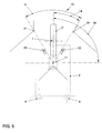
- the flap 2 ' has a receptacle 17 for the output element 6.
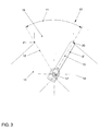
- the flap box 10 has an inlet 16 and two outlets 14, 15 for the air flowing through it.
- the actuator 3 'of the actuator system 1 is installed within the angle sector of the total adjustment angle 11 in the flap box 10, with a predefined installation angle 19.
- the fastenings in the flap boxes are designed in such a way that different installation positions result taking into account a flap tolerance. It is important that the combination of a predefined installation angle 19 for each flap, which results in an adjustment angle 18 (assignment size 1) and the total adjustment angle 11 (assignment size 2) only occurs once.
- Figures 5 to 7 three different installation positions are shown as an example, which are listed numerically in the following table.
- Figure 5 Figure 6
- Figure 7 Allocation size 1 30 ° (18) 20 ° (18 ') 30 ° (18)
- Allocation size 2 60 ° (11) 60 ° (11) 80 ° (11 ')
- the invention is not limited only to the mechanical ones shown in the figures Boundary conditions. There are also other installation conditions, for example with linear ones Adjustment paths possible.
- a plurality of flaps is essentially based on one via a bus 4 started learning phase, in which each flap 2 'by a different predefined Adjustment path 18 or 11 is moved, and a subsequent comparison of the measured adjustment paths with the in a special software of the actuators 3 'for each flap 2 'stored predefined values.
- the associated actuator 3 'then reports its Flap number via bus 4 to the control and monitoring unit 5.
- the first stop 20 can also be arranged in the vicinity of the receptacle 17 Auxiliary stop 22 may be formed. This also applies accordingly to the second stop 21 which can be designed as an auxiliary stop 23.
- each actuator 3 is recognized and is now targeted controllable.
- Each flap number must exist exactly once. Should be due of an installation error, an assignment has not been made clearly or not at all A corresponding message is output via bus 4 with the aid of error detection.
Landscapes
- Physics & Mathematics (AREA)
- Thermal Sciences (AREA)
- Engineering & Computer Science (AREA)
- Mechanical Engineering (AREA)
- Air-Conditioning For Vehicles (AREA)
- Control Of Multiple Motors (AREA)
Abstract
Description
- Figur 1:
- Eine schematische Darstellung eines Stellantriebssystems mit Bus,
- Figur 2:
- eine Seitenansicht eines Stellantriebes,
- Figur 3:
- eine Seitenansicht eines Klappenkastens mit einer Klappe,
- Figur 4:
- eine Seitenansicht der Klappe von Figur 3,
- Figur 5:
- eine Seitenansicht eines Stellantriebes mit 90° Einbauwinkel,
- Figur 6:
- eine Seitenansicht eines Stellantriebes mit alternativem Einbauwinkel zu Figur 5 und
- Figur 7:
- eine Seitenansicht eines Stellantriebes mit alternativem Klappenkasten zu den Figuren 5 und 6.
| Figur 5 | Figur 6 | Figur 7 | |
| Zuordnungsgröße 1 | 30° (18) | 20° (18') | 30° (18) |
| Zuordnungsgröße 2 | 60° (11) | 60° (11) | 80° (11') |
- 1
- Stellantriebssystem
- 2,2'
- Klappe
- 3,3'
- Stellantrieb
- 4
- Bus
- 5
- Steuer- und Kontrolleinheit
- 6
- Abtriebselement
- 7
- 1. Befestigungselement des Stellantriebes
- 8
- 2. Befestigungselement des Stellantriebes
- 9
- 3. Befestigungselement des Stellantriebes
- 10,10'
- Klappenkasten
- 11,11'
- Zuordnungsgröße 2 (Gesamtverstellwinkel)
- 12
- Klappenposition 2
- 13
- Klappenposition 1
- 14
- Auslass 2
- 15
- Auslass 1
- 16
- Einlass
- 17,17'
- Aufnahme für Abtriebselement
- 18,18'
- Zuordnungsgröße 1 (Verstellwinkel)
- 19,19'
- Einbauwinkel des Stellantriebes
- 20
- Anschlag 1
- 21
- Anschlag 2
- 22
- Hilfsanschlag 1
- 23
- Hilfsanschlag 2
Claims (13)
- Stellantriebssystem (1) mit einer Mehrzahl von universellen Stellantrieben (3,3'), die jeweils zur Verstellung wenigstens einer mechanischen Größe (2,2') vorgesehen sind, dadurch gekennzeichnet, daß die mechanischen Größen (2,2') jeweils vorgebene, spezifische mechanische Randbedingungen aufweisen, die von den Stellantrieben (3,3') derart ausgewertet werden, daß die Zuordnung eines Stellantriebs (3,3') zu der mechanischen Größe (2,2') erkennbar ist.
- Stellantriebssystem nach Anspruch 1, dadurch gekennzeichnet, daß die Stellantriebe (3,3') über einen Bus (4) ansteuerbar sind.
- Stellantriebssystem (1) nach Anspruch 1 oder 2 zum Verstellen einer Mehrzahl von Klappen, insbesondere in Klimaeinrichtungen von Kraftfahrzeugen, mit den Klappen (2,2') jeweils vorgelagerten, universellen Stellantrieben (3,3'), die über einen Bus (4) ansteuerbar sind, dadurch gekennzeichnet, dass die Klappen (2,2') in Kombination mit den Stellantrieben (3,3') untereinander vorgegebene unterschiedliche mechanische Randbedingungen aufweisen, und dass die Stellantriebe (3,3') eine spezielle Software aufweisen, mit der jeder Stellantrieb (3,3') als einer bestimmten Klappe (2,2') zugeordnet, erkennbar ist.
- Stellantriebssystem (1) nach einem der Ansprüche 1 bis 3, dadurch gekennzeichnet, dass jeder Stellantrieb (3,3') eine Blockiererkennung aufweist.
- Stellantriebssystem (1) nach einem der Ansprüche 1 bis 4, dadurch gekennzeichnet, dass die Software eine Tabelle mit einem ersten Satz von Zuordnungsgrößen zur Zuordnung eines Verstellweges (18,18') zu einer bestimmten Klappe (2,2') in einer ersten Drehrichtung aufweist.
- Stellantriebssystem (1) nach Anspruch 5, dadurch gekennzeichnet, dass die Software eine Tabelle mit einem zweiten Satz von Zuordnungsgrößen zur Zuordnung eines Verstellweges (11,11') zu einer bestimmten Klappe (2,2') in einer zweiten Drehrichtung aufweist.
- Stellantriebssystem (1) nach einem der Ansprüche 1 bis 6, dadurch gekennzeichnet, dass die Software eine Fehlererkennung bei nicht eindeutiger Klappenzuordnung aufweist.
- Verfahren zur Erkennung von universellen, busfähigen Stellantrieben (3,3'), denen jeweils eine bestimmte mechanische Größe (2,2') einer Mehrzahl von mechanischen Größen (2,2') zugeordnet ist, dadurch gekennzeichnet, daß in den Stellantrieben (3,3') eine Lernphase auslösbar ist, bei der die mechanischen Größen (2,2') um jeweils einen vordefinierten Verstellweg verfahren werden und hierbei die einem Stellantrieb (3,3') jeweils zugeordnete mechanische Größe (2,2') erkannt wird.
- Verfahren nach Anspruch 8, zur Erkennung von universellen, busfähigen Stellantrieben (3,3'), denen jeweils eine bestimmte Klappe (2,2') einer Mehrzahl von Klappen, insbesondere von Klimaeinrichtungen in Kraftfahrzeugen, zugeordnet ist, dadurch gekennzeichnet, dass von jedem Stellantrieb (3,3') über eine spezielle Software durch eine über einen Bus (4) gestartete Lernphase, bei der jede Klappe (2,2') um einen anderen vordefinierten Verstellweg verfahren wird, jeweils die ihm zugeordnete Klappe (2,2') erkannt wird.
- Verfahren nach Anspruch 8 oder 9, dadurch gekennzeichnet, dass an den Stellantrieben (3,3') eine vorgegebene einheitliche Abtriebstellung eines Abtriebselementes (6) eingestellt wird.
- Verfahren nach einem der Ansprüche 8 bis 10, dadurch gekennzeichnet, dass jede Klappe (2,2') aus einer anderen Ausgangsstellung (19,19') der Antriebsachse um einen anderen Verstellwinkel (18,18')in einer definierten Drehrichtung bis zu einem ersten Anschlag (20) in einem Klappenkasten (10) verfahren wird, woraus die Software eine erste Zuordnungsgröße bildet.
- Verfahren nach Anspruch 11, dadurch gekennzeichnet, dass jede Klappe nach Erreichen des ersten Anschlags (20, 22) in entgegengesetzter Drehrichtung bis zu einem entgegengesetzten Anschlag (21, 23) des Klappenkastens (10) verfahren wird, woraus die Software eine zweite Zuordnungsgröße bildet.
- Verfahren nach einem der Ansprüche 8 bis 12, dadurch gekennzeichnet, dass nach erfolgter eindeutiger Zuordnung anhand der Zuordnungsgrößen eine entsprechende Meldung über den Bus (4) ausgegeben wird, andernfalls eine Fehlermeldung ausgegeben wird.
Applications Claiming Priority (2)
| Application Number | Priority Date | Filing Date | Title |
|---|---|---|---|
| DE2000124216 DE10024216A1 (de) | 2000-05-17 | 2000-05-17 | Stellantriebssystem |
| DE10024216 | 2000-05-17 |
Publications (3)
| Publication Number | Publication Date |
|---|---|
| EP1155885A2 true EP1155885A2 (de) | 2001-11-21 |
| EP1155885A3 EP1155885A3 (de) | 2003-10-15 |
| EP1155885B1 EP1155885B1 (de) | 2006-06-21 |
Family
ID=7642414
Family Applications (1)
| Application Number | Title | Priority Date | Filing Date |
|---|---|---|---|
| EP01107739A Expired - Lifetime EP1155885B1 (de) | 2000-05-17 | 2001-04-02 | Stellantriebssystem |
Country Status (2)
| Country | Link |
|---|---|
| EP (1) | EP1155885B1 (de) |
| DE (2) | DE10024216A1 (de) |
Cited By (2)
| Publication number | Priority date | Publication date | Assignee | Title |
|---|---|---|---|---|
| EP1428703A3 (de) * | 2002-12-10 | 2004-08-18 | Calsonic Kansei Corporation | Steuereinrichtung für eine Klimaanlage |
| EP1226989B1 (de) * | 2001-01-24 | 2005-08-31 | Valeo Systemes Thermiques | Verfahren zum Identifizieren von Aktuatoren in Fahrzeugklimaanlagen |
Families Citing this family (2)
| Publication number | Priority date | Publication date | Assignee | Title |
|---|---|---|---|---|
| DE102007058777B4 (de) * | 2007-12-06 | 2025-05-08 | Abb Ag | Verfahren zur Inbetriebnahme von Stellantrieben |
| DE102009007109A1 (de) | 2009-02-02 | 2010-08-05 | Behr Gmbh & Co. Kg | Steuerschaltung für einen Datenbus |
Citations (2)
| Publication number | Priority date | Publication date | Assignee | Title |
|---|---|---|---|---|
| DE19507039A1 (de) | 1994-04-05 | 1995-10-12 | Smiths Industries Plc | Elektrische Verbindungsanordnung |
| DE4327537C2 (de) | 1993-08-16 | 1997-11-20 | Siemens Ag | Sensorelement für ein serielles Bussystem |
Family Cites Families (4)
| Publication number | Priority date | Publication date | Assignee | Title |
|---|---|---|---|---|
| FR1332743A (fr) * | 1962-06-09 | 1963-07-19 | Equip S E I M J Jassoud Sa Des | Rhéostat de commande |
| DE19524068A1 (de) * | 1995-07-01 | 1997-01-02 | Behr Gmbh & Co | Aktuatoranordnung und diese verwendende Vorrichtung |
| DE19621272A1 (de) * | 1996-05-25 | 1997-11-27 | Bosch Gmbh Robert | Adressierungsvorrichtung für eine Nebenstation eines seriellen Bussystems und Verfahren zur Adressierung einer Nebenstation |
| DE19828259A1 (de) * | 1998-06-25 | 1999-12-30 | Behr Gmbh & Co | Elektrische Schaltung, insbesondere für eine Heizungs- und/oder Belüftungsanlage eines Fahrzeugs |
-
2000
- 2000-05-17 DE DE2000124216 patent/DE10024216A1/de not_active Withdrawn
-
2001
- 2001-04-02 EP EP01107739A patent/EP1155885B1/de not_active Expired - Lifetime
- 2001-04-02 DE DE50110210T patent/DE50110210D1/de not_active Expired - Lifetime
Patent Citations (2)
| Publication number | Priority date | Publication date | Assignee | Title |
|---|---|---|---|---|
| DE4327537C2 (de) | 1993-08-16 | 1997-11-20 | Siemens Ag | Sensorelement für ein serielles Bussystem |
| DE19507039A1 (de) | 1994-04-05 | 1995-10-12 | Smiths Industries Plc | Elektrische Verbindungsanordnung |
Cited By (3)
| Publication number | Priority date | Publication date | Assignee | Title |
|---|---|---|---|---|
| EP1226989B1 (de) * | 2001-01-24 | 2005-08-31 | Valeo Systemes Thermiques | Verfahren zum Identifizieren von Aktuatoren in Fahrzeugklimaanlagen |
| EP1428703A3 (de) * | 2002-12-10 | 2004-08-18 | Calsonic Kansei Corporation | Steuereinrichtung für eine Klimaanlage |
| US6877669B2 (en) | 2002-12-10 | 2005-04-12 | Calsonic Kansei Corporation | Control apparatus of air conditioning system |
Also Published As
| Publication number | Publication date |
|---|---|
| DE10024216A1 (de) | 2001-11-22 |
| DE50110210D1 (de) | 2006-08-03 |
| EP1155885B1 (de) | 2006-06-21 |
| EP1155885A3 (de) | 2003-10-15 |
Similar Documents
| Publication | Publication Date | Title |
|---|---|---|
| DE69532759T2 (de) | Übertragungsvorrichtung für klimaanlage | |
| DE4308466C1 (de) | Klimasystem für ein Passagierflugzeug | |
| EP0616941B1 (de) | Anordnung zur Verhinderung des selbsttätigen Öffnens einer nicht ordnungsgemäss geschlossenen und verriegelten Tür oder Klappe im Flugzeugrumpf | |
| EP0963594B1 (de) | Modulares sicherheitsschaltgerät | |
| EP0275992A2 (de) | Maschinenanlage mit mehreren Aktoren | |
| DE60205782T2 (de) | Verfahren zum Identifizieren von Aktuatoren in Fahrzeugklimaanlagen | |
| CH649180A5 (de) | Motor-steuereinrichtung. | |
| WO1998028687A1 (de) | Verfahren zur überprüfung der funktionsfähigkeit einer recheneinheit | |
| DE19911824C2 (de) | Schaltschranküberwachungsanlage | |
| DE3232848A1 (de) | Steuerungssystem mit von digitalrechnern erzeugten steuersignalen | |
| EP1155885A2 (de) | Stellantriebssystem | |
| DE3934279C2 (de) | Verfahren zur Diagnose von zu einer Betriebssteuerung gehörenden Antriebslasten einer Brennkraftmaschine | |
| DE60311948T2 (de) | Steuereinrichtung für eine Klimaanlage | |
| DE102017121175A1 (de) | Steuerschaltung zum Ansteuern eines Elektromotors | |
| EP0756668B1 (de) | Vorrichtung und verfahren zur steuerung einer brennkraftmaschine | |
| AT400944B (de) | Vorrichtung zum steuern und regeln elektrischer, elektronischer oder elektromechanischer komponenten in schienenfahrzeugen | |
| EP1055547A1 (de) | Vorrichtung zur elektronischen Steuerung, insbesondere Schienenfahrzeugantriebskomponenten-Steuersystem | |
| EP1183577B1 (de) | Verfahren zur erzeugung eines steuerbausteins und steuerbaustein | |
| EP1639416A1 (de) | Elektronische steuereinheit und verfahren zur spezifikation einer software-architektur f r eine elektronische steuereinheit | |
| EP0639706B1 (de) | System zur Ansteuerung eines Stellglieds zur Einstellung der Luftzufuhr eines Kraftfahrzeugmotors | |
| EP0809162A2 (de) | Verfahren zur Prozesssteuerung und Prozesssteuersystem | |
| DE19933688A1 (de) | Vorrichtung zur elektronischen Steuerung, insbesondere Schienenfahrzeugantriebskomponenten-Steuersystem | |
| DE10344070B4 (de) | Antriebsmodul für eine Druckmaschine | |
| DE102020207209A1 (de) | Verfahren zur Generierung einer Diagnoseadresse von zumindest zwei Fensterheber-Steuergeräte eines Fahrzeugs, elektronisches Fensterheberdiagnosesystem und Fahrzeug | |
| EP0936515B1 (de) | Mehrprozessor-Steuervorrichtung |
Legal Events
| Date | Code | Title | Description |
|---|---|---|---|
| PUAI | Public reference made under article 153(3) epc to a published international application that has entered the european phase |
Free format text: ORIGINAL CODE: 0009012 |
|
| AK | Designated contracting states |
Kind code of ref document: A2 Designated state(s): AT BE CH CY DE DK ES FI FR GB GR IE IT LI LU MC NL PT SE TR |
|
| AX | Request for extension of the european patent |
Free format text: AL;LT;LV;MK;RO;SI |
|
| PUAL | Search report despatched |
Free format text: ORIGINAL CODE: 0009013 |
|
| AK | Designated contracting states |
Kind code of ref document: A3 Designated state(s): AT BE CH CY DE DK ES FI FR GB GR IE IT LI LU MC NL PT SE TR |
|
| AX | Request for extension of the european patent |
Extension state: AL LT LV MK RO SI |
|
| 17P | Request for examination filed |
Effective date: 20040415 |
|
| AKX | Designation fees paid |
Designated state(s): DE ES FR GB IT |
|
| 17Q | First examination report despatched |
Effective date: 20041208 |
|
| GRAP | Despatch of communication of intention to grant a patent |
Free format text: ORIGINAL CODE: EPIDOSNIGR1 |
|
| GRAS | Grant fee paid |
Free format text: ORIGINAL CODE: EPIDOSNIGR3 |
|
| GRAC | Information related to communication of intention to grant a patent modified |
Free format text: ORIGINAL CODE: EPIDOSCIGR1 |
|
| GRAF | Information related to payment of grant fee modified |
Free format text: ORIGINAL CODE: EPIDOSCIGR3 |
|
| GRAA | (expected) grant |
Free format text: ORIGINAL CODE: 0009210 |
|
| AK | Designated contracting states |
Kind code of ref document: B1 Designated state(s): DE ES FR GB IT |
|
| PG25 | Lapsed in a contracting state [announced via postgrant information from national office to epo] |
Ref country code: IT Free format text: LAPSE BECAUSE OF FAILURE TO SUBMIT A TRANSLATION OF THE DESCRIPTION OR TO PAY THE FEE WITHIN THE PRESCRIBED TIME-LIMIT;WARNING: LAPSES OF ITALIAN PATENTS WITH EFFECTIVE DATE BEFORE 2007 MAY HAVE OCCURRED AT ANY TIME BEFORE 2007. THE CORRECT EFFECTIVE DATE MAY BE DIFFERENT FROM THE ONE RECORDED. Effective date: 20060621 |
|
| REG | Reference to a national code |
Ref country code: GB Ref legal event code: FG4D Free format text: NOT ENGLISH |
|
| REF | Corresponds to: |
Ref document number: 50110210 Country of ref document: DE Date of ref document: 20060803 Kind code of ref document: P |
|
| PG25 | Lapsed in a contracting state [announced via postgrant information from national office to epo] |
Ref country code: ES Free format text: LAPSE BECAUSE OF FAILURE TO SUBMIT A TRANSLATION OF THE DESCRIPTION OR TO PAY THE FEE WITHIN THE PRESCRIBED TIME-LIMIT Effective date: 20061002 |
|
| GBT | Gb: translation of ep patent filed (gb section 77(6)(a)/1977) |
Effective date: 20060924 |
|
| PLBE | No opposition filed within time limit |
Free format text: ORIGINAL CODE: 0009261 |
|
| STAA | Information on the status of an ep patent application or granted ep patent |
Free format text: STATUS: NO OPPOSITION FILED WITHIN TIME LIMIT |
|
| EN | Fr: translation not filed | ||
| 26N | No opposition filed |
Effective date: 20070322 |
|
| PG25 | Lapsed in a contracting state [announced via postgrant information from national office to epo] |
Ref country code: FR Free format text: LAPSE BECAUSE OF FAILURE TO SUBMIT A TRANSLATION OF THE DESCRIPTION OR TO PAY THE FEE WITHIN THE PRESCRIBED TIME-LIMIT Effective date: 20070309 |
|
| PG25 | Lapsed in a contracting state [announced via postgrant information from national office to epo] |
Ref country code: FR Free format text: LAPSE BECAUSE OF FAILURE TO SUBMIT A TRANSLATION OF THE DESCRIPTION OR TO PAY THE FEE WITHIN THE PRESCRIBED TIME-LIMIT Effective date: 20060621 |
|
| REG | Reference to a national code |
Ref country code: DE Ref legal event code: R082 Ref document number: 50110210 Country of ref document: DE |
|
| PGFP | Annual fee paid to national office [announced via postgrant information from national office to epo] |
Ref country code: DK Payment date: 20170510 Year of fee payment: 17 |
|
| REG | Reference to a national code |
Ref country code: DE Ref legal event code: R119 Ref document number: 50110210 Country of ref document: DE |
|
| PG25 | Lapsed in a contracting state [announced via postgrant information from national office to epo] |
Ref country code: DE Free format text: LAPSE BECAUSE OF NON-PAYMENT OF DUE FEES Effective date: 20181101 |
|
| PGFP | Annual fee paid to national office [announced via postgrant information from national office to epo] |
Ref country code: GB Payment date: 20200429 Year of fee payment: 20 |
|
| REG | Reference to a national code |
Ref country code: GB Ref legal event code: PE20 Expiry date: 20210401 |
|
| PG25 | Lapsed in a contracting state [announced via postgrant information from national office to epo] |
Ref country code: GB Free format text: LAPSE BECAUSE OF EXPIRATION OF PROTECTION Effective date: 20210401 |
|
| P01 | Opt-out of the competence of the unified patent court (upc) registered |
Effective date: 20230523 |