EP1155765B1 - Verfahren zum kraftschlüssigen Einspannen eines Werkzeuges - Google Patents
Verfahren zum kraftschlüssigen Einspannen eines Werkzeuges Download PDFInfo
- Publication number
- EP1155765B1 EP1155765B1 EP01109257A EP01109257A EP1155765B1 EP 1155765 B1 EP1155765 B1 EP 1155765B1 EP 01109257 A EP01109257 A EP 01109257A EP 01109257 A EP01109257 A EP 01109257A EP 1155765 B1 EP1155765 B1 EP 1155765B1
- Authority
- EP
- European Patent Office
- Prior art keywords
- tool
- bore
- holder
- contact piece
- mount
- Prior art date
- Legal status (The legal status is an assumption and is not a legal conclusion. Google has not performed a legal analysis and makes no representation as to the accuracy of the status listed.)
- Expired - Lifetime
Links
- 238000000034 method Methods 0.000 title claims abstract description 45
- 238000010438 heat treatment Methods 0.000 claims abstract description 39
- 238000003780 insertion Methods 0.000 claims abstract description 18
- 230000037431 insertion Effects 0.000 claims abstract description 18
- 238000001816 cooling Methods 0.000 claims abstract description 16
- 230000003287 optical effect Effects 0.000 claims description 22
- 230000033001 locomotion Effects 0.000 claims description 15
- 238000005303 weighing Methods 0.000 claims description 14
- 239000000463 material Substances 0.000 claims description 10
- 239000002826 coolant Substances 0.000 claims description 6
- 230000000694 effects Effects 0.000 claims description 4
- 238000003801 milling Methods 0.000 claims description 4
- 239000013013 elastic material Substances 0.000 claims description 3
- 239000004033 plastic Substances 0.000 claims description 3
- 230000035515 penetration Effects 0.000 abstract description 17
- 238000005520 cutting process Methods 0.000 description 13
- 230000008901 benefit Effects 0.000 description 6
- 230000006978 adaptation Effects 0.000 description 4
- 230000006698 induction Effects 0.000 description 4
- 230000008569 process Effects 0.000 description 4
- 239000000919 ceramic Substances 0.000 description 3
- 244000059549 Borneo rubber Species 0.000 description 2
- 230000001939 inductive effect Effects 0.000 description 2
- 229910052751 metal Inorganic materials 0.000 description 2
- 239000002184 metal Substances 0.000 description 2
- 230000000149 penetrating effect Effects 0.000 description 2
- 229910001315 Tool steel Inorganic materials 0.000 description 1
- 230000004913 activation Effects 0.000 description 1
- 230000002411 adverse Effects 0.000 description 1
- 230000033228 biological regulation Effects 0.000 description 1
- 230000008859 change Effects 0.000 description 1
- 230000008878 coupling Effects 0.000 description 1
- 238000010168 coupling process Methods 0.000 description 1
- 238000005859 coupling reaction Methods 0.000 description 1
- 238000006073 displacement reaction Methods 0.000 description 1
- 238000004519 manufacturing process Methods 0.000 description 1
- 238000003825 pressing Methods 0.000 description 1
- 230000007115 recruitment Effects 0.000 description 1
- 230000002040 relaxant effect Effects 0.000 description 1
- 230000007704 transition Effects 0.000 description 1
- UONOETXJSWQNOL-UHFFFAOYSA-N tungsten carbide Chemical compound [W+]#[C-] UONOETXJSWQNOL-UHFFFAOYSA-N 0.000 description 1
- 238000010792 warming Methods 0.000 description 1
Images


Classifications
-
- B—PERFORMING OPERATIONS; TRANSPORTING
- B23—MACHINE TOOLS; METAL-WORKING NOT OTHERWISE PROVIDED FOR
- B23Q—DETAILS, COMPONENTS, OR ACCESSORIES FOR MACHINE TOOLS, e.g. ARRANGEMENTS FOR COPYING OR CONTROLLING; MACHINE TOOLS IN GENERAL CHARACTERISED BY THE CONSTRUCTION OF PARTICULAR DETAILS OR COMPONENTS; COMBINATIONS OR ASSOCIATIONS OF METAL-WORKING MACHINES, NOT DIRECTED TO A PARTICULAR RESULT
- B23Q17/00—Arrangements for observing, indicating or measuring on machine tools
- B23Q17/09—Arrangements for observing, indicating or measuring on machine tools for indicating or measuring cutting pressure or for determining cutting-tool condition, e.g. cutting ability, load on tool
- B23Q17/0904—Arrangements for observing, indicating or measuring on machine tools for indicating or measuring cutting pressure or for determining cutting-tool condition, e.g. cutting ability, load on tool before or after machining
- B23Q17/0919—Arrangements for measuring or adjusting cutting-tool geometry in presetting devices
- B23Q17/0923—Tool length
-
- B—PERFORMING OPERATIONS; TRANSPORTING
- B23—MACHINE TOOLS; METAL-WORKING NOT OTHERWISE PROVIDED FOR
- B23B—TURNING; BORING
- B23B31/00—Chucks; Expansion mandrels; Adaptations thereof for remote control
- B23B31/02—Chucks
- B23B31/10—Chucks characterised by the retaining or gripping devices or their immediate operating means
- B23B31/117—Retention by friction only, e.g. using springs, resilient sleeves, tapers
- B23B31/1179—Retention by friction only, e.g. using springs, resilient sleeves, tapers using heating and cooling
-
- B—PERFORMING OPERATIONS; TRANSPORTING
- B23—MACHINE TOOLS; METAL-WORKING NOT OTHERWISE PROVIDED FOR
- B23P—METAL-WORKING NOT OTHERWISE PROVIDED FOR; COMBINED OPERATIONS; UNIVERSAL MACHINE TOOLS
- B23P11/00—Connecting or disconnecting metal parts or objects by metal-working techniques not otherwise provided for
- B23P11/02—Connecting or disconnecting metal parts or objects by metal-working techniques not otherwise provided for by first expanding and then shrinking or vice versa, e.g. by using pressure fluids; by making force fits
- B23P11/025—Connecting or disconnecting metal parts or objects by metal-working techniques not otherwise provided for by first expanding and then shrinking or vice versa, e.g. by using pressure fluids; by making force fits by using heat or cold
- B23P11/027—Connecting or disconnecting metal parts or objects by metal-working techniques not otherwise provided for by first expanding and then shrinking or vice versa, e.g. by using pressure fluids; by making force fits by using heat or cold for mounting tools in tool holders
-
- B—PERFORMING OPERATIONS; TRANSPORTING
- B23—MACHINE TOOLS; METAL-WORKING NOT OTHERWISE PROVIDED FOR
- B23Q—DETAILS, COMPONENTS, OR ACCESSORIES FOR MACHINE TOOLS, e.g. ARRANGEMENTS FOR COPYING OR CONTROLLING; MACHINE TOOLS IN GENERAL CHARACTERISED BY THE CONSTRUCTION OF PARTICULAR DETAILS OR COMPONENTS; COMBINATIONS OR ASSOCIATIONS OF METAL-WORKING MACHINES, NOT DIRECTED TO A PARTICULAR RESULT
- B23Q17/00—Arrangements for observing, indicating or measuring on machine tools
- B23Q17/22—Arrangements for observing, indicating or measuring on machine tools for indicating or measuring existing or desired position of tool or work
- B23Q17/2216—Arrangements for observing, indicating or measuring on machine tools for indicating or measuring existing or desired position of tool or work for adjusting the tool into its holder
- B23Q17/2225—Arrangements for observing, indicating or measuring on machine tools for indicating or measuring existing or desired position of tool or work for adjusting the tool into its holder with the toolholder as reference-element
-
- Y—GENERAL TAGGING OF NEW TECHNOLOGICAL DEVELOPMENTS; GENERAL TAGGING OF CROSS-SECTIONAL TECHNOLOGIES SPANNING OVER SEVERAL SECTIONS OF THE IPC; TECHNICAL SUBJECTS COVERED BY FORMER USPC CROSS-REFERENCE ART COLLECTIONS [XRACs] AND DIGESTS
- Y10—TECHNICAL SUBJECTS COVERED BY FORMER USPC
- Y10T—TECHNICAL SUBJECTS COVERED BY FORMER US CLASSIFICATION
- Y10T29/00—Metal working
- Y10T29/49—Method of mechanical manufacture
- Y10T29/49764—Method of mechanical manufacture with testing or indicating
- Y10T29/49771—Quantitative measuring or gauging
- Y10T29/49776—Pressure, force, or weight determining
-
- Y—GENERAL TAGGING OF NEW TECHNOLOGICAL DEVELOPMENTS; GENERAL TAGGING OF CROSS-SECTIONAL TECHNOLOGIES SPANNING OVER SEVERAL SECTIONS OF THE IPC; TECHNICAL SUBJECTS COVERED BY FORMER USPC CROSS-REFERENCE ART COLLECTIONS [XRACs] AND DIGESTS
- Y10—TECHNICAL SUBJECTS COVERED BY FORMER USPC
- Y10T—TECHNICAL SUBJECTS COVERED BY FORMER US CLASSIFICATION
- Y10T29/00—Metal working
- Y10T29/49—Method of mechanical manufacture
- Y10T29/49826—Assembling or joining
- Y10T29/49863—Assembling or joining with prestressing of part
- Y10T29/49865—Assembling or joining with prestressing of part by temperature differential [e.g., shrink fit]
-
- Y—GENERAL TAGGING OF NEW TECHNOLOGICAL DEVELOPMENTS; GENERAL TAGGING OF CROSS-SECTIONAL TECHNOLOGIES SPANNING OVER SEVERAL SECTIONS OF THE IPC; TECHNICAL SUBJECTS COVERED BY FORMER USPC CROSS-REFERENCE ART COLLECTIONS [XRACs] AND DIGESTS
- Y10—TECHNICAL SUBJECTS COVERED BY FORMER USPC
- Y10T—TECHNICAL SUBJECTS COVERED BY FORMER US CLASSIFICATION
- Y10T29/00—Metal working
- Y10T29/49—Method of mechanical manufacture
- Y10T29/49826—Assembling or joining
- Y10T29/49908—Joining by deforming
-
- Y—GENERAL TAGGING OF NEW TECHNOLOGICAL DEVELOPMENTS; GENERAL TAGGING OF CROSS-SECTIONAL TECHNOLOGIES SPANNING OVER SEVERAL SECTIONS OF THE IPC; TECHNICAL SUBJECTS COVERED BY FORMER USPC CROSS-REFERENCE ART COLLECTIONS [XRACs] AND DIGESTS
- Y10—TECHNICAL SUBJECTS COVERED BY FORMER USPC
- Y10T—TECHNICAL SUBJECTS COVERED BY FORMER US CLASSIFICATION
- Y10T29/00—Metal working
- Y10T29/53—Means to assemble or disassemble
- Y10T29/53439—Means to assemble or disassemble including provision to utilize thermal expansion of work
-
- Y—GENERAL TAGGING OF NEW TECHNOLOGICAL DEVELOPMENTS; GENERAL TAGGING OF CROSS-SECTIONAL TECHNOLOGIES SPANNING OVER SEVERAL SECTIONS OF THE IPC; TECHNICAL SUBJECTS COVERED BY FORMER USPC CROSS-REFERENCE ART COLLECTIONS [XRACs] AND DIGESTS
- Y10—TECHNICAL SUBJECTS COVERED BY FORMER USPC
- Y10T—TECHNICAL SUBJECTS COVERED BY FORMER US CLASSIFICATION
- Y10T408/00—Cutting by use of rotating axially moving tool
- Y10T408/94—Tool-support
- Y10T408/95—Tool-support with tool-retaining means
-
- Y—GENERAL TAGGING OF NEW TECHNOLOGICAL DEVELOPMENTS; GENERAL TAGGING OF CROSS-SECTIONAL TECHNOLOGIES SPANNING OVER SEVERAL SECTIONS OF THE IPC; TECHNICAL SUBJECTS COVERED BY FORMER USPC CROSS-REFERENCE ART COLLECTIONS [XRACs] AND DIGESTS
- Y10—TECHNICAL SUBJECTS COVERED BY FORMER USPC
- Y10T—TECHNICAL SUBJECTS COVERED BY FORMER US CLASSIFICATION
- Y10T409/00—Gear cutting, milling, or planing
- Y10T409/30—Milling
- Y10T409/309352—Cutter spindle or spindle support
- Y10T409/309408—Cutter spindle or spindle support with cutter holder
Definitions
- the invention relates to a method for the frictional clamping of a Tool with his shaft in a hole of a tool holder throughshrinking by heating and cooling of this, in which the axial insertion depth of the shaft is set in the bore by adjustment.
- the heating takes place with preference inductive.
- this method with thermal clamping of tools is a high-precision attachment of the tools, eg. As drills, cutters od. Like., Achievable.
- the tool holder is heated at least in the region of a sleeve portion containing the bore, so that the bore increases.
- the tool is inserted with its shaft in the thus enlarged bore.
- the shank of the tool is frictionally held in the bore of the tool holder, which has shrunk again due to the cooling.
- the diameter of the bore of the tool holder and the shank of the tool are chosen so that upon cooling creates a non-positive and rotationally fixed connection, which is not released during fast turning due to the centrifugal forces.
- the tool holder is reheated, whereby the bore of this enlarged, until the tool can be pulled out with its shaft from the tool holder.
- the relaxation is only possible because the warming spreads from outside to inside, so that initially only z. B. the sleeve portion of the tool holder is heated before the heat reaches the clamped shaft of the tool. This ensures that initially stretched the sleeve portion, so that the even colder shank of the tool can be released when relaxing from the hole.
- the axial insertion depth the shaft can be set exactly into the bore of the tool holder, also taking into account the fact that in the subsequent Cooling also a change in length happens. It is known for clamping a tool first to heat the tool holder until its Bore enlarged so far that then the tool with his shaft can be plugged into this. This is the insertion depth when plugging selected according to a specification, what u. U. also by one in the Tool holder integrated stop can be additionally specified. The insertion and setting of the insertion depth in the heated done Condition of the tool holder with accompanying thermal expansion the inner mounting hole. This method works only if sufficient time for this during the short heating phase Available and if tools with low thermal expansion, e.g. made of tungsten carbide or ceramic, are used because of these Tool material is not to be feared that the tool holder supplied heat soon at the transition to the tool shank to a Expansion can also lead to this and clamping during insertion.
- tools with low thermal expansion e.g. made of tungsten carbide or ceramic
- the invention is based on the object, a method of the aforementioned To design a style so that a very precise adjustment of the insertion depth of the Tools with simplified design effort of the tool holder itself is possible and in this case no restriction regarding the material pairing Tool holder / tool is about as existing, only tools with low thermal expansion, z. B. hard metal, ceramic od. Like., At to use this method.
- the object is in a method of the type mentioned in accordance with Invention solved by the features in claim 1.
- the relevant Cutting geometry and not about the front side of the back Tool shank used creating a highly accurate setting is possible.
- a simplification is achieved by having an inner Adjusting screw with threaded hole to accommodate this can be omitted, thereby the tool holder is easier and less expensive and also the danger a possible strain of mechanical parts is eliminated.
- the heating of the tool holder is turned on with due to heating of increasing bore of the tool holder,
- the tool penetrates with its shaft in the now larger bore the tool holder.
- This penetration movement occurs either at vertical arrangement due to weight forces. It can be at vertical Arrangement or even with other spatial orientation of the arrangement instead by hand and / or by means of gear means and / or by means of a Actuator od.
- a mechanical stop is detected which is at a predetermined nominal dimension is adjusted and fixed and the contact piece, in particular a movable holder of the contact piece, is assigned and upon penetration of the Shank into the hole the penetration path by hitting this stop limited.
- a further advantageous embodiment of the invention provides that the Tool with its shank in one to the free end of the bore of the Tool holder coaxial centering support hole of a support, especially one of the tool holder itself, is introduced, wherein the tool holder is in the unheated state that the Holder with its contact piece is then placed on the tool that Thereafter, the tool in opposite directions to penetrate into the bore of the Tool receiving counteracting force and thus the clamping of the tool between the contact piece and the counterforce is activated and thereafter the heating of the tool holder is started with accompanying axial penetration of the tool with the shaft in the Drill the tool holder until the holder abuts the stop, and that then then the heating of the tool holder stopped and after cooling, the effect of the counterforce is lifted.
- an optical measuring system be kept with lighting device, recording device and screen with enlarged reproduction of the recording area. This can by Adjustment of the seated on the tool contact piece relative to the holder with measuring system a setting of the optical measuring system with optical Touching a given reference geometry of the tool done, z. B. probing the tip of a drill, the highest cutting edge of a milling cutter, the first or second stage of a step tool or by probing another measuring edge of the tool.
- a scale adjusted to adjust the nominal size is, in particular finely adjusted and then in its set position is fixed in relation to the material measure, z. B. is clamped and in this Position then a mechanical stop for the holder of the contact piece, possibly even the seated optical measuring system forms.
- a electrical switching contact is closed, by means of which the supply in particular electrical energy for heating the tool holder is interrupted.
- This switching contact can be in a particularly simple manner Be part of the attack and / or touching this holder or be formed by these yourself.
- the counter-acting to penetrate the tool shank into the bore Counterforce can, depending on the design of the tool and / or the Tool holder in a mechanical manner, eg. B. by means of a stop, a gripper od. Like., Generated and transmitted to the tool. at Such tools, which are clamped with their entire shaft, or the are designed differently in terms of geometry and which is why it is not possible to grasp them mechanically or in any other mechanical To act on the counter force, it is particularly advantageous if the counterforce is generated by means of a compressed gas cushion, which within the Hole of the tool holder is maintained. It is advantageous to maintain this compressed gas cushion until until after the end of the Heating the tool holder this during a subsequent holding time has cooled.
- a compressed gas z. B. compressed air
- the inner coolant channels contain, it may be advantageous if for the generation of the Druckgaspolsters in this case, a control of the flow rate of the Compressed gas, z. B. About a restriction, takes place until the necessary gas pressure is reached.
- the size of the counterforce, in particular of the compressed gas cushion is set so that these same or is greater than the counteracting weight of one in the bore of the Tool holder receivable tool; because at z. B. vertical Arrangement of the tool holder with hole and vertically penetrating Shank of the tool in the hole acts in the vertical direction Weight of the tool. Before reaching the given Nominal dimension and before reaching a correspondingly set stop, in the case of this vertical penetration movement of the holder with the contact piece can impact, in addition to the weight of the tool also the weight of the holder with parts of it.
- weights can, but not necessarily, be absorbed by the opposing force after reaching the nominal size and thus striking the holder at the stop the weight of the stop with contact piece and other on the holder sitting parts is then picked up by the stop and by the Counterforce thus only the weight of the tool is to be included.
- the size of the counterforce may be advantageous to adapt the size of the counterforce to vary tools with different geometry. For example, can Adjustment of the weight of each introduced tool by weighing be determined by means of a weighing device and the size of the counterforce in Adaptation to each determined and specified. This can be z. B. realize in such a way that one before inserting the tool in the Support hole of the tool holder first, the weight of the Tool holder and the carrier of this weighs and in a subsequent Weighing process now in the support hole of the tool holder Tool used the weight of the aforementioned parts together with the Tool determined by weighing and by subtraction so that the pure Tool weight receives.
- Such an adaptation of the size of the counterforce different tool geometries is advantageous if a given size of the pressure for the compressed gas cushion not all Tool geometries is sufficient.
- the holder with the contact piece through Weight and / or by hand and / or by means of gear means and / or by means of an actuator od. Like. Is moved, with a not through Weight-bearing movement is especially advantageous if the Penetration of the shank of the tool into the bore of the Tool holder does not happen in the vertical direction but in any to transverse direction, z. B. in a horizontal arrangement and horizontal penetration of the tool. It may also be advantageous if the movement of the holder is such that the contact piece a Linear motion approximately coaxial or parallel to the longitudinal axis of the tool and / or transversely.
- a further advantageous embodiment of the method according to the invention Provides that the holder and the adjustable stop are coupled with each other are or can be coupled, that by moving the holder z. In both Movement directions are made the setting of the stop can.
- This has the advantage that the stop itself does not have its own actuator od. Like. Needed for adjustment but to the effect on the holder Weight force od. Like. Gear means or actuator or manual operation is used.
- Direction z. B. by means of positive contact, z. B. by striking, is taken.
- the measuring element with its contact surface against the facing lower end face of the tool moves and the latter touched.
- This lower measuring element is set in this way and this function controlled by software.
- the software calculates the required travel range for the lower measuring element to set the tool to nominal size.
- the end face of the Measuring element, the target stop position for the facing lower end of the Tool occupies.
- the tool is shrunk, the Tool in the hole of the tool holder moves down until whose end face on the facing end face of the lower measuring member strikes and thus the axial target position is reached. Because the tool at maintains these adjusting operations its axial relative rotational position and the the end of the tool facing end face is not displaced, leads the adjustment of the lower measuring element up to the nominal stop position not to any falsification.
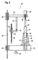
- a tool holder 10 with therein contained bore 11 for receiving a cylindrical shaft 12 of a Tool 13 represents.
- the tool holder 10 may be a Any component act, z. B. a spindle section, a portion of a feed, an adapter od.
- the tool 13 is also a any tool, eg. As a drill, taps, cutters, a Step tool od.
- a drill taps, cutters
- Step tool od Like.
- the bore 11 in the tool holder 10 can be open at the bottom and for the coaxial support of the tool 13th prior to shrinking a coaxial to the bore 11 centering Support bore 14 at the free end, with respect to the Diameter slightly larger than the bore 11 is dimensioned so that in cold state of the tool holder the tool 13 with the end of Shaft 12 coaxially received and centered in this support hole 14 held and coaxially supported against displacement down.
- a device 20 provided, which has a carrier 21 for receiving the tool holder 10 and at a distance above the support 21 has a holder 22, both of which are e.g.
- the holder 22 is a carrier only schematically indicated Contact piece 25, which in the embodiment shown in Fig. 2 either adjustable or by means of a thread 26 relative to the holder 22 adjustable and is finely adjustable.
- the contact piece 25 is relative to the tool holder 10th at least vertically movable and can from the top at the free end of the Tool 13, z. As a local tip, cutting edge od.
- To the plant brought as shown in Fig. 1 to 3 is illustrated. At least the Area of the contact piece 25, in contact with the tool 13, z. B. its Tip, cutting edge od.
- Fig. 2 and 3 As from the remaining part of the Contact piece 25 separated part 27 is shown schematically, consists with Advantage of a material that compared to the material of the tool 13 more forgiving, z. B. softer, is, for. B. rubber, plastic od. Like. Federä Anlagen elastic material. Instead, the part 27 can not be made by means of a shown spring with respect to the remaining part of the contact piece 25th be formed cushioned part.
- the device 20 also has a stop 28, which is shown in more detail in Figs. 2 and 3, where the stop 28 in Reference to an indicated measuring scale 29, z. B. a scale for the Setting a nominal size s (Fig. 1) is adjustable, in particular finely adjustable is.
- the stop 28 can in the respectively adjusted position relative to Measuring standard 29 are fixed, z. B. by means of a schematic only indicated clamping screw 30 are clamped.
- Between the stop 28 on the one hand and in the course of the recruitment from above Holder 22 on the other hand may be an electrical not particularly shown Switching be closed, by means of which the supply in particular electrical energy is interrupted, which is used for heating the Tool holder 10 was previously released.
- the switching contact can by corresponding surfaces of the stopper 28 and / or the holder 22nd be formed directly.
- Fig. 2 and 3 protrudes from the holder 22, an extension 31st down, the mechanical stop of the holder 22 on the stop 28th causes and z. B. stores a ball 32 for the contact.
- the probing of the upper free end takes place of the tool 13 by means of the contact piece 25 by placing this, in particular of the part 27, and probing, wherein a fine adjustment of Contact piece 25 relative to the holder 22 by touching the handle 34th and rotation in the thread 26 is possible.
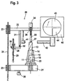
- the device is with a optical measuring system 40 which is held on the holder 22 and a schematically indicated lighting device 41, opposite Recording device 42 and a screen 43 with enlarged playback of the receiving area.
- the optical measuring system 40 is firmly seated on the holder 22.
- contact piece 25 is the Vertical position of the holder 22 adjusted.
- said geared Means or such an actuator are not particularly shown here, the z. B. off can consist of a servomotor.
- the Screen 43 shows the enlarged view of an upper part 44 of the geometry of the Tool 13.
- the holder 22 is coupled to the adjustable stop 28 or coupled, so that carried by adjusting the holder 22 of the stop 28 and can be adjusted accordingly.
- stop 28 will pass through magnetic force in the movement of the holder 22 upwards from the Extension 31 of the holder 22 moves upward until the nominal dimension s is set, whereupon the stop 28 by means of clamping, z. B. the Clamping screw 30 is fixed in this set position.
- a possible opposing adjustment of the stop 28 takes place z. B. by positive contact, z. B. by striking the holder 22 directly or by extension 31, in the opposite direction.
- the device 20 is further provided with a provided only schematically indicated weighing device 35, which has the advantage that this is a variation of the magnitude of the drag according to arrow 33 in FIG Adaptation to tools 13 with different geometry allows.
- the Weighing device 35 makes it possible to adjust the weight of each introduced tool 13 by weighing to determine and adapt to the weighing result to specify the size of the opposing force 33.
- the weight of the carrier 21 and the tool holder 10 can be determined.
- the tool 13 with the end of the shaft 12 from above into the tool holder 10th used it with the end of the shaft 12 in the support hole 14 so is recorded that a coaxial mount and centering and a axial support from below takes place. Then in a second Weighing process by means of the weighing device 35, the weight of the carrier 21, the Tool holder 10 and the tool 13 determined. From the Difference can be calculated then the weight of the tool 13.
- the opposing force represented only by arrow 33 can by means of a Compressed gas cushion generated within the bore 11 of the Tool holder 10 is maintained, namely when setting and Shrink in until until after heating stops Tool holder 10 latter during a subsequent holding time has cooled.
- this compressed gas cushion can in the bore 11th the tool holder 10 z. B. through a channel from below or over other existing, not shown coolant channels, a compressed gas, eg. B. Compressed air, are introduced.
- the size of the drag especially the Druckgaspolsters, it is advantageously set so that it is greater than that counteracting weight of one in the bore 11 of the Tool holder 10 recordable tool 13. Then it is needed normally the weighing device 35 and the weighing processes described not, which are only used when the size of the counterforce according to Arrow 33 varies in adaptation to tools 13 with different geometry becomes.
- the inner coolant channels contain, escape on the pressure gas when applying the compressed gas cushion can, takes place for the generation of the compressed gas cushion a regulation of the Volume flow of the compressed gas, z. B. via a throttle until the necessary gas pressure is reached.
- a regulation of the Volume flow of the compressed gas, z. B. via a throttle until the necessary gas pressure is reached.
- the size of the drag according to arrow 33, in particular of the compressed gas cushion, adjusted so that they is greater than the counteracting weight of one in the bore 11 of the Tool holder 10 recordable tool 13, so that it is the Weighing device 35 is not required.
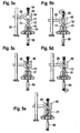
- Fig. 4 are simplified in the form of a flow sketch individual stages in the Passing through the individual process steps indicated.
- the device 20 with the components in the state a.
- the stopper 28 is set to the nominal dimension s and in the set position has been fixed, z. B. by clamping by means of Clamping screw 30.
- the stop 28 is through Magnetic connection with the holder 22 and movement of this z. B. by means of a acting on it, not shown actuator, for. As motors, in this Position has been moved upwards.
- the tool 13 from above into the Tool holder 10 is introduced, wherein the tool 13 with the lower End of his shaft 12 in the support bore 14 coaxially centered and axially is supported.
- the device 20 may also be a z. B. above the tool holder 10 located support, the in turn, a corresponding support hole coaxial with the bore 11th runs, or has another other type of support of the tool 13 causes such that it is aligned coaxially with the bore 11 and is initially supported against axial downward movement.
- Tool 13 is used to position the tool 13 at its free end the movable contact piece 25 brought to bear, as the second Representation b in Fig. 4 shows.
- this counterforce is by pressing the Contact piece 25 still need to make a fine adjustment
- the contact piece 25 is adjusted relative to the holder 22 with measuring system 40.
- the heating of the tool holder 10 by Release of electrical energy for the induction coil, not shown started.
- the initiated heating of the tool holder 10 has an enlargement of the bore 11 result, so that in the vertical arrangement the tool 13 into the bore 11 from above and penetrate after can move down.
- the short heating phase of 5 - 10 seconds thus reaches the Shank 12 of the tool 13 deeper into the bore 11 into the predetermined nominal dimension s is reached z. B. by striking the holder 22 on Stop 28. Another slip of the shaft 12 in the bore 11th is prevented by the still effective counterforce 33.
- Fig. 5a to 5e is analogous to Fig. 4a to 4d, another embodiment of a Method shown in which for the parts that the first embodiment correspond, the same reference numerals are used, so that thus the Avoiding repetition on the description of the first embodiment Reference is made.
- the target position of the in the Tool holder 10 shrunk tool shank 12 and the Tool 13 by a lower stop in the form of a Measuring member 50 predetermined, preferably from a micrometer screw consists, wherein the stop by the end face 51 of the adjustable part of the Measuring element 50 is specified.
- the tool 13th introduced with the shaft 12 in the bore 11 of the tool holder 10.
- the optical measuring system 40 in particular a profile projector, along a guide 24 as far down moves until a contact piece 25 with strikes its contact surface on the cutting edge of the tool 13.
- This Contact piece 25 e.g. a micrometer screw, then becomes relative to Measuring system 40 set, in particular finely adjusted so that the cutting edge of Tool 13 after the crosshairs of the measuring system 40, in particular Profile projector, is aligned.
- the measuring system 40 in particular the Profile projector, measures the height of the cutting edge of the tool 13. This Condition is shown in Fig. 5b.
- a measuring member 50 e.g. a micrometer screw, in opposite directions and so far moved up to the tool 13 until the end face 51 of the Measuring member 50 at the lower facing end side of the tool thirteenth strikes. Under certain circumstances, the measuring element 50 also goes beyond this still at least slightly further up.
- This movement of Measuring element 50 is a not further shown software of Computer system controlled. Starting from the position of the contact piece 25th and the optical measuring system 40 is now for the lower measuring element 50, in particular its end face 51, the required travel by means of Calculates software that is required for the target stop position and for in order to set the tool 13 to the specified size when shrinking.
- the calculated position for the measuring member 50 is then by adjusting the Measuring element 50 is set. This state is shown in Fig. 5d. After that the tool 13 is shrunk into the tool holder 10. While the heating of the tool holder 10 drops the tool 13 in the bore 11 down to it with its front side on the end face 51 of the measuring element 50th strikes and has reached its target position. Afterwards, the cooling of the Tool holder 10.
Landscapes
- Engineering & Computer Science (AREA)
- Mechanical Engineering (AREA)
- A Measuring Device Byusing Mechanical Method (AREA)
- Machine Tool Sensing Apparatuses (AREA)
- Jigs For Machine Tools (AREA)
- Cutting Tools, Boring Holders, And Turrets (AREA)
- Drilling And Boring (AREA)
Applications Claiming Priority (2)
| Application Number | Priority Date | Filing Date | Title |
|---|---|---|---|
| DE10024423 | 2000-05-19 | ||
| DE10024423A DE10024423A1 (de) | 2000-05-19 | 2000-05-19 | Verfahren zum kraftschlüssigen Einspannen eines Werkzeuges |
Publications (2)
| Publication Number | Publication Date |
|---|---|
| EP1155765A1 EP1155765A1 (de) | 2001-11-21 |
| EP1155765B1 true EP1155765B1 (de) | 2005-10-12 |
Family
ID=7642562
Family Applications (1)
| Application Number | Title | Priority Date | Filing Date |
|---|---|---|---|
| EP01109257A Expired - Lifetime EP1155765B1 (de) | 2000-05-19 | 2001-04-14 | Verfahren zum kraftschlüssigen Einspannen eines Werkzeuges |
Country Status (5)
| Country | Link |
|---|---|
| US (2) | US6588083B2 (enExample) |
| EP (1) | EP1155765B1 (enExample) |
| JP (1) | JP2002046029A (enExample) |
| AT (1) | ATE306348T1 (enExample) |
| DE (2) | DE10024423A1 (enExample) |
Families Citing this family (28)
| Publication number | Priority date | Publication date | Assignee | Title |
|---|---|---|---|---|
| MXPA03001793A (es) * | 2000-09-01 | 2004-11-01 | Gemini Group Inc | Sistema para preajustar herramientas ajustadas en caliente. |
| DE10131352A1 (de) | 2001-06-26 | 2003-01-09 | Zoller Gmbh & Co Kg E | Verfahren und Vorrichtung zum Einschrumpfen von Werkzeugen, insbesondere Zerspanungswekzeugen |
| DE10138107B4 (de) * | 2001-08-03 | 2009-01-15 | Gühring, Jörg, Dr. | Schrumpfgerät mit Längeneinstellung |
| EP1310323B1 (de) | 2001-11-12 | 2011-03-30 | Franz Haimer Maschinenbau KG | Schrumpfvorrichtung für einen Werkzeughalter |
| DE10222092B4 (de) * | 2001-11-12 | 2015-02-12 | Franz Haimer Maschinenbau Kg | Schrumpfvorrichtung für einen Werkzeughalter |
| DE20203783U1 (de) | 2002-03-08 | 2003-07-17 | Franz Haimer Maschinenbau KG, 86568 Hollenbach | Voreinstellvorrichtung für einen Schrumpf-Werkzeughalter |
| FR2838072B1 (fr) * | 2002-04-04 | 2004-09-10 | Fournel | Procedes de frettage s'outils sur porte-outils |
| DE10244759B4 (de) * | 2002-09-26 | 2005-12-08 | Bauer, Walter, Dr.-Ing. | Spannfutter zum thermischen Einschrumpfen von Schäften |
| DE10249072A1 (de) * | 2002-10-21 | 2004-06-09 | E. Zoller GmbH & Co. KG Einstell- und Messgeräte | Verfahren zum Befestigen eines Werkzeugs in einem Werkzeugfutter |
| DE10253106A1 (de) * | 2002-11-13 | 2004-06-03 | E. Zoller GmbH & Co. KG Einstell- und Messgeräte | Schrumpfvorrichtung |
| DE10257226B4 (de) * | 2002-12-07 | 2014-06-12 | E. Zoller GmbH & Co. KG Einstell- und Messgeräte | Verfahren zum Befestigen eines Werkzeugs |
| ATE404322T1 (de) * | 2002-12-11 | 2008-08-15 | Zoller Gmbh & Co Kg | Werkzeughaltevorrichtung und verfahren zum positionieren eines werkzeugs |
| DE10309015A1 (de) * | 2003-03-01 | 2004-09-16 | Wagner-Werkzeugsysteme Müller GmbH | Werkzeugschrumpfaufnahme |
| US7143490B2 (en) * | 2003-03-12 | 2006-12-05 | Kennametal Inc. | Tap process for hard workpieces |
| US7770278B2 (en) * | 2003-03-24 | 2010-08-10 | University Of North Carolina At Charlotte | Methods for creating assemblies and disassembling |
| DE10349241A1 (de) * | 2003-10-20 | 2005-07-07 | E. Zoller Gmbh & Co. Kg | Haltevorrichtung und Verfahren zum Vermessen eines Werkzeugs |
| DE202004004424U1 (de) * | 2004-03-20 | 2004-07-15 | Bilz Werkzeugfabrik Gmbh & Co. Kg | Einrichtung zum thermischen Spannen und Entspannen von Werkzeugen in Schrumpffuttern |
| DE102004027559A1 (de) * | 2004-06-04 | 2005-12-22 | Bilz Werkzeugfabrik Gmbh & Co. Kg | Verfahren zum Befestigen eines Werkzeuges in einer Werkzeugaufnahme |
| FR2890583B1 (fr) * | 2005-09-13 | 2009-03-13 | E P B Soc Par Actions Simplifi | Procede de reglage de la profondeur d'emmanchement d'un outil dans un porte-outil et dispositif pour la mise en oeuvre de ce procede |
| DE102006011007A1 (de) | 2005-12-16 | 2007-06-21 | Gühring Ohg | Schrumpffutter mit exzentrischer Positionierung |
| WO2007086112A1 (ja) * | 2006-01-25 | 2007-08-02 | Osg Corporation | 焼きばめ式工具ユニット及びその焼きばめ式工具ユニットに使用される工具ホルダ並びに回転工具 |
| DE102007042915A1 (de) | 2007-09-08 | 2009-03-12 | Bilz Werkzeugfabrik Gmbh & Co. Kg | Einrichtung zum Einstellen und Befestigen eines Werkzeuges in einer Aufnahme eines Werkzeugfutters, insbesondere durch Schrumpfbefestigung |
| US7959387B2 (en) * | 2007-10-03 | 2011-06-14 | Kennametal Inc. | Shrink fit sleeve for tool holder |
| US9074326B2 (en) | 2011-06-02 | 2015-07-07 | Dacon Industries | Hinged rail seal clip |
| KR101397721B1 (ko) * | 2012-08-06 | 2014-05-20 | 김수장 | 자동공구교환장치용 툴프리세터 |
| DE102013203558A1 (de) * | 2013-03-01 | 2014-09-04 | Bilz Werkzeugfabrik Gmbh & Co. Kg | Werkzeugkopf |
| JP7091274B2 (ja) * | 2019-03-18 | 2022-06-27 | オリンパス株式会社 | 接合方法、及び接合装置 |
| DE102023106799A1 (de) * | 2023-03-17 | 2024-09-19 | Franz Haimer Maschinenbau Kg | Messhülse für eine Werkzeugvermessung |
Family Cites Families (13)
| Publication number | Priority date | Publication date | Assignee | Title |
|---|---|---|---|---|
| US4818161A (en) * | 1985-10-15 | 1989-04-04 | Cook Harold D | Tool holder system and method of use |
| JPH04129605A (ja) * | 1990-09-19 | 1992-04-30 | Mori Seiki Co Ltd | 工作機械の主軸装置 |
| US5280671A (en) * | 1992-05-12 | 1994-01-25 | Fx Marquart Gmbh | Process and device for clamping tools in a clamping chuck |
| US5311654A (en) * | 1992-09-25 | 1994-05-17 | Cook Harold D | Tool holder system and method of making |
| DE19638808B4 (de) * | 1996-09-20 | 2009-03-19 | Fx Marquart Gmbh | Werkzeughalter zur Befestigung eines Werkzeuges an einer Werkzeugmaschine und Spannzange |
| DE19638822A1 (de) * | 1996-09-20 | 1998-03-26 | Fx Marquart Gmbh | Spanneinrichtung zur Befestigung eines Werkzeuges an einer Werkzeugmaschine sowie Vorrichtung zum Spannen von Werkzeugen im Schrumpfsitz |
| DE29716051U1 (de) * | 1997-09-08 | 1998-01-15 | I. Rineck GmbH, 33428 Harsewinkel | Vorrichtung zur Schrumpfhalterung eines Werkzeugs in einem Werkzeugträger |
| DE19860254C1 (de) * | 1998-12-24 | 2000-05-31 | Daimler Chrysler Ag | Spannfutter |
| JP2001062638A (ja) * | 1999-08-31 | 2001-03-13 | Hitachi Hometec Ltd | 誘導加熱式焼きばめ装置 |
| JP2001150213A (ja) * | 1999-11-29 | 2001-06-05 | Daishowa Seiki Co Ltd | 焼ばめによる工具の着脱装置 |
| JP2001179544A (ja) * | 1999-12-20 | 2001-07-03 | Cgk Kk | 電磁誘導加熱による刃物工具の焼きばめ装置及び刃物工具ホルダーの工具把持部 |
| DE10015322A1 (de) * | 2000-03-28 | 2001-10-18 | Zoller Gmbh & Co Kg E | Verfahren zum Einstellen eines Einstellmaßes eines Werkzeuges |
| DE10025007B4 (de) * | 2000-05-22 | 2011-06-01 | Harbin Measuring & Cutting Tool Group Co., Ltd. | Verfahren und Vorrichtung zum thermischen Spannen und Entspannen von Werkzeugen |
-
2000
- 2000-05-19 DE DE10024423A patent/DE10024423A1/de not_active Withdrawn
-
2001
- 2001-04-14 AT AT01109257T patent/ATE306348T1/de not_active IP Right Cessation
- 2001-04-14 EP EP01109257A patent/EP1155765B1/de not_active Expired - Lifetime
- 2001-04-14 DE DE50107652T patent/DE50107652D1/de not_active Expired - Lifetime
- 2001-05-17 US US09/860,162 patent/US6588083B2/en not_active Expired - Lifetime
- 2001-05-18 JP JP2001149120A patent/JP2002046029A/ja active Pending
-
2003
- 2003-04-16 US US10/414,716 patent/US6701597B2/en not_active Expired - Fee Related
Also Published As
| Publication number | Publication date |
|---|---|
| JP2002046029A (ja) | 2002-02-12 |
| US20010042295A1 (en) | 2001-11-22 |
| DE10024423A1 (de) | 2001-11-22 |
| EP1155765A1 (de) | 2001-11-21 |
| US6701597B2 (en) | 2004-03-09 |
| ATE306348T1 (de) | 2005-10-15 |
| US20030192161A1 (en) | 2003-10-16 |
| US6588083B2 (en) | 2003-07-08 |
| DE50107652D1 (de) | 2005-11-17 |
Similar Documents
| Publication | Publication Date | Title |
|---|---|---|
| EP1155765B1 (de) | Verfahren zum kraftschlüssigen Einspannen eines Werkzeuges | |
| DE602004006174T2 (de) | Werkzeughalter für Werkzeugmaschine, mit Mitteln zur Regelung der Bohrtiefe | |
| EP2799169A2 (de) | Verfahren und Vorrichtung zum Einstellen auf eine Motorspindel einer Werkzeugmaschine aufgespannter einstellbarer Werkzeuge | |
| EP1310323A2 (de) | Schrumpfvorrichtung für einen Werkzeughalter | |
| DE10015322A1 (de) | Verfahren zum Einstellen eines Einstellmaßes eines Werkzeuges | |
| DE202004013916U1 (de) | Gerät zum Spannen eines Rotationswerkzeugs in einem Werkzeughalter | |
| DE19925193A1 (de) | Piezoelektrischer Einstellmechanismus | |
| CH698920B1 (de) | Werkstückspindelstock. | |
| EP0303564B1 (de) | Verfahren zum Messen der Einzugskraft an der Schnittstelle zwischen einem Werkzeug und der Spindelnase einer Werkzeugmaschine | |
| DE10138107B4 (de) | Schrumpfgerät mit Längeneinstellung | |
| EP3445528B1 (de) | Vorrichtung und verfahren zum einsetzen eines werkzeugs in eine werkzeugaufnahme | |
| WO2004091847A2 (de) | Verfahren und vorrichtung zur voreinstellung der länge einer werkzeugeinheit | |
| DE69000324T2 (de) | Bohrspindel-tiefeneinstellvorrichtung. | |
| DE10317576B4 (de) | Vorrichtung zum Einspannen eines Rotationswerkzeugs in einen Werkzeughalter | |
| DE102009011682B4 (de) | Verfahren zur automatisierten Vermessung eines Werkzeugs in einer Bearbeitungsmaschine, Verfahren zur Verschleißkontrolle oder zur spanenden Bearbeitung eines Werkstücks sowie Bearbeitungsmaschine | |
| CH698147B1 (de) | Schleifmaschine und Verfahren zum Einrichten eines Werkstückträgers an einer Schleifmaschine. | |
| EP0554772B1 (de) | Feinbohrwerkzeug | |
| EP0280862A2 (de) | Führungseinrichtung für ein Tiefbohrwerkzeug | |
| DE102020121932A1 (de) | Werkzeugspannvorrichtung mit Längeneinstellung durch Fluidausstoß sowie Verfahren zum längenbestimmten Einspannen | |
| EP1602443B1 (de) | Verfahren und Vorrichtung zum Befestigen eines Werkzeuges in einer Werkzeugaufnahme | |
| DE10222092A1 (de) | Schrumpfvorrichtung für einen Werkzeughalter | |
| EP1990153B1 (de) | Vorrichtung und Verfahren zum Einbringen eines Befestigungselements in eine Bohrung in einem Werkstück | |
| DE202005006567U1 (de) | Vorrichtung zum Vermessen eines Werkzeugs | |
| DE10225839A1 (de) | Verfahren und Vorrichtung zur Herstellung eines Maschinenwerkzeugs | |
| DE29502537U1 (de) | Vorrichtung zur insbesondere spanenden Bearbeitung eines Werkstückes |
Legal Events
| Date | Code | Title | Description |
|---|---|---|---|
| PUAI | Public reference made under article 153(3) epc to a published international application that has entered the european phase |
Free format text: ORIGINAL CODE: 0009012 |
|
| AK | Designated contracting states |
Kind code of ref document: A1 Designated state(s): AT BE CH CY DE DK ES FI FR GB GR IE IT LI LU MC NL PT SE TR |
|
| AX | Request for extension of the european patent |
Free format text: AL;LT;LV;MK;RO;SI |
|
| 17P | Request for examination filed |
Effective date: 20011219 |
|
| AKX | Designation fees paid |
Free format text: AT BE CH CY DE DK ES FI FR GB GR IE IT LI LU MC NL PT SE TR |
|
| 17Q | First examination report despatched |
Effective date: 20050221 |
|
| GRAP | Despatch of communication of intention to grant a patent |
Free format text: ORIGINAL CODE: EPIDOSNIGR1 |
|
| GRAS | Grant fee paid |
Free format text: ORIGINAL CODE: EPIDOSNIGR3 |
|
| GRAA | (expected) grant |
Free format text: ORIGINAL CODE: 0009210 |
|
| AK | Designated contracting states |
Kind code of ref document: B1 Designated state(s): AT BE CH CY DE DK ES FI FR GB GR IE IT LI LU MC NL PT SE TR |
|
| PG25 | Lapsed in a contracting state [announced via postgrant information from national office to epo] |
Ref country code: NL Free format text: LAPSE BECAUSE OF FAILURE TO SUBMIT A TRANSLATION OF THE DESCRIPTION OR TO PAY THE FEE WITHIN THE PRESCRIBED TIME-LIMIT Effective date: 20051012 Ref country code: FI Free format text: LAPSE BECAUSE OF FAILURE TO SUBMIT A TRANSLATION OF THE DESCRIPTION OR TO PAY THE FEE WITHIN THE PRESCRIBED TIME-LIMIT Effective date: 20051012 Ref country code: IE Free format text: LAPSE BECAUSE OF FAILURE TO SUBMIT A TRANSLATION OF THE DESCRIPTION OR TO PAY THE FEE WITHIN THE PRESCRIBED TIME-LIMIT Effective date: 20051012 |
|
| REG | Reference to a national code |
Ref country code: GB Ref legal event code: FG4D Free format text: NOT ENGLISH |
|
| REG | Reference to a national code |
Ref country code: CH Ref legal event code: EP |
|
| GBT | Gb: translation of ep patent filed (gb section 77(6)(a)/1977) |
Effective date: 20051012 |
|
| REG | Reference to a national code |
Ref country code: IE Ref legal event code: FG4D Free format text: LANGUAGE OF EP DOCUMENT: GERMAN |
|
| REF | Corresponds to: |
Ref document number: 50107652 Country of ref document: DE Date of ref document: 20051117 Kind code of ref document: P |
|
| PG25 | Lapsed in a contracting state [announced via postgrant information from national office to epo] |
Ref country code: GR Free format text: LAPSE BECAUSE OF FAILURE TO SUBMIT A TRANSLATION OF THE DESCRIPTION OR TO PAY THE FEE WITHIN THE PRESCRIBED TIME-LIMIT Effective date: 20060112 Ref country code: SE Free format text: LAPSE BECAUSE OF FAILURE TO SUBMIT A TRANSLATION OF THE DESCRIPTION OR TO PAY THE FEE WITHIN THE PRESCRIBED TIME-LIMIT Effective date: 20060112 Ref country code: DK Free format text: LAPSE BECAUSE OF FAILURE TO SUBMIT A TRANSLATION OF THE DESCRIPTION OR TO PAY THE FEE WITHIN THE PRESCRIBED TIME-LIMIT Effective date: 20060112 |
|
| PG25 | Lapsed in a contracting state [announced via postgrant information from national office to epo] |
Ref country code: ES Free format text: LAPSE BECAUSE OF FAILURE TO SUBMIT A TRANSLATION OF THE DESCRIPTION OR TO PAY THE FEE WITHIN THE PRESCRIBED TIME-LIMIT Effective date: 20060123 |
|
| PG25 | Lapsed in a contracting state [announced via postgrant information from national office to epo] |
Ref country code: PT Free format text: LAPSE BECAUSE OF FAILURE TO SUBMIT A TRANSLATION OF THE DESCRIPTION OR TO PAY THE FEE WITHIN THE PRESCRIBED TIME-LIMIT Effective date: 20060313 |
|
| NLV1 | Nl: lapsed or annulled due to failure to fulfill the requirements of art. 29p and 29m of the patents act | ||
| PG25 | Lapsed in a contracting state [announced via postgrant information from national office to epo] |
Ref country code: AT Free format text: LAPSE BECAUSE OF NON-PAYMENT OF DUE FEES Effective date: 20060414 |
|
| PG25 | Lapsed in a contracting state [announced via postgrant information from national office to epo] |
Ref country code: LI Free format text: LAPSE BECAUSE OF NON-PAYMENT OF DUE FEES Effective date: 20060430 Ref country code: CH Free format text: LAPSE BECAUSE OF NON-PAYMENT OF DUE FEES Effective date: 20060430 Ref country code: MC Free format text: LAPSE BECAUSE OF NON-PAYMENT OF DUE FEES Effective date: 20060430 Ref country code: BE Free format text: LAPSE BECAUSE OF NON-PAYMENT OF DUE FEES Effective date: 20060430 |
|
| REG | Reference to a national code |
Ref country code: IE Ref legal event code: FD4D |
|
| ET | Fr: translation filed | ||
| PLBE | No opposition filed within time limit |
Free format text: ORIGINAL CODE: 0009261 |
|
| STAA | Information on the status of an ep patent application or granted ep patent |
Free format text: STATUS: NO OPPOSITION FILED WITHIN TIME LIMIT |
|
| 26N | No opposition filed |
Effective date: 20060713 |
|
| REG | Reference to a national code |
Ref country code: CH Ref legal event code: PL |
|
| BERE | Be: lapsed |
Owner name: BILZ WERKZEUGFABRIK G.M.B.H. & CO. KG Effective date: 20060430 |
|
| PG25 | Lapsed in a contracting state [announced via postgrant information from national office to epo] |
Ref country code: LU Free format text: LAPSE BECAUSE OF NON-PAYMENT OF DUE FEES Effective date: 20060414 Ref country code: TR Free format text: LAPSE BECAUSE OF FAILURE TO SUBMIT A TRANSLATION OF THE DESCRIPTION OR TO PAY THE FEE WITHIN THE PRESCRIBED TIME-LIMIT Effective date: 20051012 |
|
| PG25 | Lapsed in a contracting state [announced via postgrant information from national office to epo] |
Ref country code: CY Free format text: LAPSE BECAUSE OF FAILURE TO SUBMIT A TRANSLATION OF THE DESCRIPTION OR TO PAY THE FEE WITHIN THE PRESCRIBED TIME-LIMIT Effective date: 20051012 |
|
| REG | Reference to a national code |
Ref country code: DE Ref legal event code: R082 Ref document number: 50107652 Country of ref document: DE Representative=s name: WITTE, WELLER & PARTNER, DE Ref country code: DE Ref legal event code: R082 Ref document number: 50107652 Country of ref document: DE Representative=s name: WITTE, WELLER & PARTNER PATENTANWAELTE MBB, DE |
|
| PGFP | Annual fee paid to national office [announced via postgrant information from national office to epo] |
Ref country code: GB Payment date: 20140422 Year of fee payment: 14 |
|
| PGFP | Annual fee paid to national office [announced via postgrant information from national office to epo] |
Ref country code: IT Payment date: 20140430 Year of fee payment: 14 Ref country code: FR Payment date: 20140422 Year of fee payment: 14 |
|
| GBPC | Gb: european patent ceased through non-payment of renewal fee |
Effective date: 20150414 |
|
| PG25 | Lapsed in a contracting state [announced via postgrant information from national office to epo] |
Ref country code: GB Free format text: LAPSE BECAUSE OF NON-PAYMENT OF DUE FEES Effective date: 20150414 Ref country code: IT Free format text: LAPSE BECAUSE OF NON-PAYMENT OF DUE FEES Effective date: 20150414 |
|
| REG | Reference to a national code |
Ref country code: FR Ref legal event code: ST Effective date: 20151231 |
|
| PG25 | Lapsed in a contracting state [announced via postgrant information from national office to epo] |
Ref country code: FR Free format text: LAPSE BECAUSE OF NON-PAYMENT OF DUE FEES Effective date: 20150430 |
|
| PGFP | Annual fee paid to national office [announced via postgrant information from national office to epo] |
Ref country code: DE Payment date: 20190528 Year of fee payment: 19 |
|
| REG | Reference to a national code |
Ref country code: DE Ref legal event code: R119 Ref document number: 50107652 Country of ref document: DE |
|
| PG25 | Lapsed in a contracting state [announced via postgrant information from national office to epo] |
Ref country code: DE Free format text: LAPSE BECAUSE OF NON-PAYMENT OF DUE FEES Effective date: 20201103 |