EP1155608A2 - A mowing machine - Google Patents
A mowing machine Download PDFInfo
- Publication number
- EP1155608A2 EP1155608A2 EP01203331A EP01203331A EP1155608A2 EP 1155608 A2 EP1155608 A2 EP 1155608A2 EP 01203331 A EP01203331 A EP 01203331A EP 01203331 A EP01203331 A EP 01203331A EP 1155608 A2 EP1155608 A2 EP 1155608A2
- Authority
- EP
- European Patent Office
- Prior art keywords
- mowing machine
- wheel
- cutter bar
- mowing
- rotor
- Prior art date
- Legal status (The legal status is an assumption and is not a legal conclusion. Google has not performed a legal analysis and makes no representation as to the accuracy of the status listed.)
- Withdrawn
Links
Images

Classifications
-
- A—HUMAN NECESSITIES
- A01—AGRICULTURE; FORESTRY; ANIMAL HUSBANDRY; HUNTING; TRAPPING; FISHING
- A01D—HARVESTING; MOWING
- A01D43/00—Mowers combined with apparatus performing additional operations while mowing
- A01D43/10—Mowers combined with apparatus performing additional operations while mowing with means for crushing or bruising the mown crop
- A01D43/102—Bruising control devices
Abstract
Description
- The invention relates to a mowing machine according to the preamble of claim 1.
- Such a mowing machine is known.
- The invention has for its object to improve the above described mowing machine.
- In accordance with the invention, this is achieved by the features as defined in claim 1. By means of the motor-driven wheel there can be obtained, in the direction of travel of the mowing machine, a force by which the torque exerted on the tractor by the mowing machine is compensated entirely or partially. Because of this, the tractor driver does hardly need to apply a course correction, if at all, to move the mowing machine straight ahead over the plot. In an embodiment of the invention, the wheel is disposed near the free end of the cutter bar. By disposing the wheel at the free end of the cutter bar, the "arm" will be maximum with respect to the centre of rotation of the mowing machine, so that, by the force of the wheel, there can be obtained a counter torque which is as large as possible. According to again an other inventive feature, the mowing machine comprises coupling points for its connection to the three-point hitch of a tractor.
- According to an other aspect of the invention, the wheel is driven by a hydraulic motor. According to an inventive feature, the wheel is hinge-connected with the cutter bar so as to be able to adapt itself to the unevennesses of the soil. In a preferred embodiment, the wheel is capable of deflecting with respect to the cutter bar against spring action.
- In accordance with a further inventive feature, the motor-driven wheel is provided with a further control mechanism for driving the wheel. According to a further aspect of the invention, the further control mechanism may comprise adjusting means by means of which the number of revolutions and/or the torque of the wheel can be adjusted. In this manner, depending on the working conditions, it is possible to adjust an optimum number of revolutions and/or an optimum torque. In order to give the farmer an indication regarding the number of revolutions and/or the torque to be adjusted, according to a feature of the invention, the further control mechanism comprises measuring means with the aid of which it is possible to determine the force which, during operation and with respect to the direction of travel of the mowing machine, is exerted by the cutter bar on the vehicle by which the mowing machine is moved forward. In ideal conditions, this force should be negligible.
- According to another embodiment of the invention, the further control mechanism comprises measuring means with the aid of which it is possible to determine the angle at which, during operation, the cutter bar is located relative to the vehicle by which the mowing machine is moved forward. In ideal conditions, the angle between the vehicle and the cutter bar, during operation as well as out of operation, will be equal. In an embodiment of the invention, the measuring means include strain gauges which are disposed on the frame.
- In accordance with still another embodiment of the invention, the measuring means comprise a clinometer.
- According to still another embodiment of the invention, the measuring means comprise a slip meter by means of which the slip of the driven wheel can be determined.
- According to a further inventive feature, the mowing machine comprises indication means, such as a display by means of which the farmer is informed about the number of revolutions and/or the force by which the crushing device is driven. On the basis of this information, the farmer is able to adjust an optimum distance between rotor and cutter bar thus obtaining a proper crushing function.
- For the purpose of automating the adjustment of the distance between the cutter bar and the rotor, according to an inventive feature, the mowing machine comprises a control mechanism by means of which the adjusting means are activated on the basis of signals supplied by the measuring means. In order to obtain a stable control, i.e. a non-permanent adjustment of the rotor with respect to the cutter bar, according to again an other feature of the invention, the control mechanism includes an adjustable threshold value for activating the adjusting means. In accordance with a further aspect of the invention, the mowing machine comprises signal means supplying an acoustic or optical signal when the crushing device is crushing the crop insufficiently. In this manner the farmer is informed in an early stage about the function of the crushing device.
- In a first embodiment of the invention, the measuring means comprise a revolution counter with the aid of which the number of revolutions of the rotor can be determined. A decreasing number of revolutions may be an indication that the crop is crushed insufficiently. According to again another embodiment of the invention, the measuring means comprise a torque meter by means of which the drive torque of the rotor can be determined. Also the drive torque of the rotor is an indication whether the crusher is properly functioning or not. According to a further embodiment of the invention, the measuring means comprise a dynamometer. According to an inventive feature, the dynamometer may include strain gauges which are disposed on the bearings of the rotor. When there is supplied much crop to the crusher, the pressure on the bearings will increase, which can be measured by means of the strain gauges.
- In accordance with a further embodiment of the invention, the measuring means comprise a feeler which is disposed between the rotor and the frame of the mowing machine. In a preferred embodiment of the invention, the feeler is constituted by a beater bar with a dynamometer mounted thereon.
- According to an inventive feature, the adjusting means comprise a cylinder or an electromotor. By means of the cylinder or the electromotor the rotor can be adjusted in an approximately horizontal plane with respect to the cutter bar. In accordance with a further feature of the invention, the adjusting means are arranged on the frame of the mowing machine at either side of the rotor. In still another embodiment of the invention, both the rotor and a beater bar can be adjusted with respect to the cutter bar, while it is still possible to adjust the distance between the rotor and the beater bar.
- The invention further relates to a mowing machine comprising a cutter bar, a crushing device including a rotor provided with crushing elements, and adjusting means by means of which the distance between the crushing elements and the cutter bar is adjusted, characterized in that the adjusting means are mechanically activated by means of a feeler which is mounted on the frame and comes into contact with the flow of crop during operation. The above-mentioned mechanically activated adjusting means have the advantage that no electric or hydraulic lines need to be disposed from the tractor to the mowing machine. In order to achieve a smooth adjustment of the rotor, according to an inventive feature, the adjusting means comprise a transmission.
- The invention will now be further explained with reference to exemplary embodiments as represented by the drawings, in which:
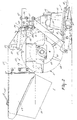
- Figure 1 shows a plan view of an embodiment of the mower-conditioner not being part of the invention;
- Figure 2 shows a side view of the mowing machine depicted in Figure 1;
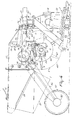
- Figure 3 shows a plan view of an embodiment of the mowing machine according to the invention, and
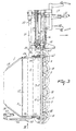
- Figure 4 shows a side view of the mowing machine depicted in Figure 3.
-
- The mowing machine 1 represented in the drawings comprises a
mowing unit 2 and acrushing device 3 including a rotor 4 and crushing elements 5, as well as an element 7 constituting, in conjunction with this crushingdevice 3, a crop feed-throughchannel 6. - The
mowing unit 2 comprises a cutter bar 8, above which there are arranged a half-dozen mowing discs 9 which are capable of rotation about vertical axes and are provided withcutting blades 10. A suspension beam 11 is fitted above and parallel to the cutter bar 8. The connection between the cutter bar 8 and the suspension beam 11 is constituted at one end by a gearbox 12 (see Figure 2) and at the other by a supportingelement 13 extending from the suspension beam 11 obliquely rearwards and downwards, and connected to this supportingelement 13 near the foot of the latter, a connectingelement 14, extending essentially horizontally, which is also connected with the cutter bar 8. - The mowing machine is in the usual way capable of being swung about an approximately
horizontal pivot shaft 15 which extends in the direction of travel in operative condition and is connected with acarrying arm 16 comprising a carryingframe 17 which enables the mowing machine to be coupled to a three-point hitch of a tractor or a similar vehicle. The drive of the mowing machine is effected from a power-take-off shaft 18 of a (non-shown) tractor through various transmission elements in agearbox 12 connected to thecarrying arm 16, from whichgearbox 12 themowing unit 2 is driven by a belt transmission drive 19 and the various transmission elements in thegearbox 12, and the drive of the crushingdevice 3 is effected by means of anintermediate shaft 21 provided withuniversal joints 20. - The outermost mowing disc on the side where the
elements crop guide device 22. - There is provided a
frame 23 slidably connected with the suspension beam 11, whichframe 23 comprises supportingbeams 24, abracket 25 fixed in position under each of these, and anangle plate 26 fixed in position under this bracket. The crushingdevice 3 is pivot-mounted between theangle plates 26. In addition, top-plate parts 27 and side-plate parts slidable frame 23, with the rear side-plate parts 29 being slanted inwardly in rearward direction and being bent outwardly at the bottom side. At the inside of the side-plate parts 29 there are providedfurther side plates 30, which have at their bottom side apart 31 extending inwardly and which can be moved further inwardly by means of agrip 32 to enable a desired swath limitation to be obtained. - Further, a
first support 33 and asecond support 34 are fixed in position on the supportingbeams 24. A connectingstrip 35 pivot-mounted in thesecond support 34 is capable of being fixed in position in thefirst support 33 by means of ashaft 36 and holes 37 such that the position of this connectingstrip element 35 and, with that, thestrip 38 which is fixedly fastened to the latter and extends in the longitudinal direction of the crushingdevice 3, with thebeater bar 39 being attached to it, determines the desired size of the crop feed-through channel 6 (see Figure 2). - The rotor 4 of the
crushing device 3 comprises a cylindrical carrier 40 on which the crushing elements 5 are disposed in mutually staggered positions. The crushing elements 5 are tapered, they have an I-section and they also protrude from the roller outwards. The outermost crushingelements 41 at either side of the cylindrical carrier 40 are flat, tapered and also protruding from the roller outwards. Thus, the outermost crushing elements are dagger-shaped and preferably made from a flat strip of spring steel having a thickness of approximately 3 mms. Viewed from above, the outermostcrushing elements 41 are disposed at a distance of about one centimetre from the side-plate parts 28. Because, during operation, the dagger-shaped outermost flatcrushing elements 41 move relatively close along the side-plate parts 28, any material for crushing which has adhered to the side-plate parts 28 or which has accumulated in the corners of the crop feed-throughchannel 6 is cut up. Since the cut-up crop winds less easily and is better removable, the rotor 4 is prevented from dragging, and the crop feed-throughchannel 6 and possibly the rotor 4 is/are prevented from getting clogged with crop. The application of a relatively thin strip of spring steel for the outermostcrushing elements 41 offers the advantage that the crushingelements 41, when viewed in the direction of rotation of the rotor 4, are relatively rigid, whereas the crushingelements 41 in a direction perpendicular to the direction of rotation of the rotor 4 are capable of easily deflecting and springing back again. The latter may be the case when, for instance, foreign matter such as a piece of wood or stone lands in the rotor 4. It will be obvious that more than two dagger-shaped crushingelements 41 can be placed on the cylindrical carrier 40, and that the crushingelements 41 can be made of a different material having the same properties as spring steel, such as e.g. a synthetic material. - As has been set forth hereinbefore, it is possible to shift the
frame 23, wherein the crushingdevice 3 is rotatably suspended, with respect to the cutter bar 8 and to fix it again in position. For this purpose, the two supportingbeams 24 comprise, near the front, aU-section part 42 provided with a hole 43 in which abolt 44 is inserted, whichbolt 44 is optionally inserted in any one of a series ofholes 45 in astrip 46 fixedly connected with the suspension beam 11 of the cutter bar 8. Near the end of thestrips 46 there is also provided aclamping bracket 47, through which the box-like supporting beams 24 are fed and by means of which the supportingbeams 24 can be clamped onto thestrip 46. - The distance between the
circle 48 described by the crushingelements 5, 41 and the cutter bar 8 can be adjusted by slightly loosening the clampingbrackets 47 and removing thebolts 44 and shifting the supportingbeams 24 with respect to thestrips 46. When the correct distance has been set, theframe 23 can be fixed again by means of the suspension beam 11 of the cutter bar 8 by tightening the clampingbrackets 47 and mounting thebolts 44. It will be obvious that the adjustment of the crushingdevice 3 in relation to themowing unit 2 can also take place in a way different from what has been set forth hereinbefore. A continuous adjustment of the crushingdevice 3 with respect to themowing unit 2 can be obtained, for instance, by adjusting the crushingdevice 3 by means of a spindle or a cylinder. - Figures 3 and 4 show an embodiment of the mowing machine according to the invention, which mowing machine comprises measuring means with the aid of which it is possible to determine the number of revolutions and/or the force by which the crushing
device 3 is driven. As shown in Figure 4, the measuring meanscomprise dynamometers 49 disposed on thebearings 50 in which the rotor 4 is located. Thedynamometers 49 include (non-shown) strain gauges by means of which the force can be determined which is exerted by theshaft 51 of the rotor 4 on thebearings 50. The force exerted by theshaft 51 on thebearings 50 of the rotor 4 then constitutes an indication of the amount of material supplied by themowing unit 2 to the rotor 4. - Via lugs 52,
rotatable cylinders 53 are arranged on thebrackets 25. At their other ends, thecylinders 53 are rotatably disposed on lugs 54 which are connected with theangle plates 26 in which the rotor 4 is located. Viewed in the direction of travel, there are disposed (non-shown) slotted holes in thebrackets 25, which slotted holes constitute a guide means for having theangle plates 26 and consequently the rotor 4 moved by means of thecylinders 53. For this purpose, theangle plates 26 are disposed in the slotted holes via longitudinal guide means 55. When thedynamometer 49 has established that the rotor 4 is overloaded because too much material is supplied thereto, thecylinders 53 are activated by a (non-shown) further control mechanism, so that the distance between the rotor 4 and themowing unit 2 is increased. - To the outer supporting
beam 24 of the mowing machine 1 there is furthermore attached a motor-drivenwheel 57 via arearwardly extending arm 56. Thearm 56 is made of a T-section so as to be torsion-rigid. Near thewheel 57 there is further arranged a controllablehydraulic motor 58 by means of which thewheel 57 can be driven at a variable speed and/or torque. The other end of thearm 56 is hinge-connected about ahorizontal shaft 59 with the supportingbeam 24 of theframe 23. Furthermore, a (non-shown) torsion spring is disposed around theshaft 59, the arrangement being such that thewheel 57 is movable in height against spring action so as to be capable of adapting itself to unevennesses of the soil. - The mowing machine 1 further comprises a (non-shown) further control mechanism for driving the
wheel 57. By means of the further control mechanism the number of revolutions and/or the torque of thewheel 57 can be adjusted. For this purpose, the further control mechanism comprises measuring means 60 disposed on the suspension beam 11, with the aid of which measuring means it is possible to determine the force which, during operation and with respect to the direction of travel of the machine, is exerted by the cutter bar 8 on the vehicle by which the mowing machine 1 is moved forward. The measuring means 60 comprise (non-shown) strain gauges which are adapted to measure the bending of the suspension beam 11, which is a measure for the above-mentioned force.
Claims (15)
- A mowing machine comprising a cutter bar (8) and a wheel (57) connected thereto, characterized in that the wheel (57) is motor-driven.
- A mowing machine as claimed in claim 1, characterized in that the wheel (57) is disposed near the free end of the cutter bar (8).
- A mowing machine as claimed in claim 1 or 2, characterized in that the mowing machine (1) comprises coupling points for its connection to the three-point hitch of a tractor.
- A mowing machine as claimed in any one of the preceding claims, characterized in that the wheel (57) is driven by a hydraulic motor (58).
- A mowing machine as claimed in any one of the preceding claims, characterized in that the wheel (57) is hinge-connected with the cutter bar (8).
- A mowing machine as claimed in claim 5, characterized in that the wheel (57) is capable of deflecting with respect to the cutter bar (8) against spring action.
- A mowing machine as claimed in any one of the preceding claims, characterized in that the motor-driven wheel (57) is provided with a further control mechanism for driving the wheel (57).
- A mowing machine as claimed in claim 7, characterized in that the further control mechanism comprises adjusting means by means of which the number of revolutions and/or the torque of the wheel (57) can be adjusted.
- A mowing machine as claimed in claim 8, characterized in that the further control mechanism comprises measuring means (60) with the aid of which it is possible to determine the force which, during operation and with respect to the direction of travel of the machine, is exerted by the cutter bar (8) on the vehicle by which the mowing machine (1) is moved forward.
- A mowing machine as claimed in claim 9, characterized in that the measuring means include strain gauges which are disposed on the frame (23).
- A mowing machine as claimed in claim 9 or 10, characterized in that the further control mechanism comprises measuring means with the aid of which it is possible to determine the angle at which, during operation, the cutter bar (8) is located relative to the vehicle by which the mowing machine (1) is moved forward.
- A mowing machine as claimed in claim 11, characterized in that the measuring means comprise a clinometer.
- , A mowing machine as claimed in any one of the preceding claims, characterized in that the measuring means comprise a slip meter by means of which the slip of the driven wheel can be determined.
- A mowing machine comprising a cutter bar (8), a crushing device (3) including a rotor (4) provided with crushing elements (5), and adjusting means by means of which the distance between the crushing elements (5) and the cutter bar (8) can be adjusted, characterized in that the adjusting means are mechanically activated by means of a feeler which is mounted on the frame (23) and comes into contact with the flow of crop during operation.
- A mowing machine as claimed in claim 14, characterized in that the adjusting means comprise a transmission.
Priority Applications (1)
| Application Number | Priority Date | Filing Date | Title |
|---|---|---|---|
| EP01203331A EP1155608A3 (en) | 1996-07-29 | 1997-07-11 | A mowing machine |
Applications Claiming Priority (4)
| Application Number | Priority Date | Filing Date | Title |
|---|---|---|---|
| EP96202142 | 1996-07-29 | ||
| EP96202142 | 1996-07-29 | ||
| EP01203331A EP1155608A3 (en) | 1996-07-29 | 1997-07-11 | A mowing machine |
| EP97929602A EP0861020B1 (en) | 1996-07-29 | 1997-07-11 | A mowing machine |
Related Parent Applications (1)
| Application Number | Title | Priority Date | Filing Date |
|---|---|---|---|
| EP97929602A Division EP0861020B1 (en) | 1996-07-29 | 1997-07-11 | A mowing machine |
Publications (2)
| Publication Number | Publication Date |
|---|---|
| EP1155608A2 true EP1155608A2 (en) | 2001-11-21 |
| EP1155608A3 EP1155608A3 (en) | 2002-09-11 |
Family
ID=8224241
Family Applications (2)
| Application Number | Title | Priority Date | Filing Date |
|---|---|---|---|
| EP97929602A Expired - Lifetime EP0861020B1 (en) | 1996-07-29 | 1997-07-11 | A mowing machine |
| EP01203331A Withdrawn EP1155608A3 (en) | 1996-07-29 | 1997-07-11 | A mowing machine |
Family Applications Before (1)
| Application Number | Title | Priority Date | Filing Date |
|---|---|---|---|
| EP97929602A Expired - Lifetime EP0861020B1 (en) | 1996-07-29 | 1997-07-11 | A mowing machine |
Country Status (9)
| Country | Link |
|---|---|
| US (1) | US20020026778A1 (en) |
| EP (2) | EP0861020B1 (en) |
| JP (1) | JPH11512936A (en) |
| AT (1) | ATE218032T1 (en) |
| AU (1) | AU723609B2 (en) |
| DE (1) | DE69712863T2 (en) |
| DK (1) | DK0861020T3 (en) |
| NZ (1) | NZ330139A (en) |
| WO (1) | WO1998004112A2 (en) |
Families Citing this family (5)
| Publication number | Priority date | Publication date | Assignee | Title |
|---|---|---|---|---|
| NL1006826C2 (en) † | 1997-08-22 | 1999-02-23 | Maasland Nv | Agricultural machine and method for its use. |
| NL1009562C2 (en) * | 1998-07-06 | 2000-01-10 | Maasland Nv | Mower. |
| US6840027B2 (en) * | 2003-03-28 | 2005-01-11 | Vermeer Manufacturing Company | Forage conditioner-tedder |
| US6912832B1 (en) * | 2004-06-16 | 2005-07-05 | Vermeer Manufacturing Company | Mower suspension |
| DE102017008126A1 (en) * | 2017-08-30 | 2019-02-28 | Müthing GmbH & Co. KG | Agricultural working device |
Citations (7)
| Publication number | Priority date | Publication date | Assignee | Title |
|---|---|---|---|---|
| US2582177A (en) * | 1948-06-04 | 1952-01-08 | Max B Swisher | Powered caster wheel for vehicles |
| DE1138573B (en) * | 1956-06-02 | 1962-10-25 | Stockey & Schmitz | Rear mower for agricultural tractors |
| US3523410A (en) * | 1968-04-26 | 1970-08-11 | Clyde L Taylor | Apparatus for mowing,conditioning and windrowing forage |
| US5423165A (en) * | 1992-05-14 | 1995-06-13 | Kuhn, S.A. | Cutting machine which adapts to contour of ground |
| EP0682859A2 (en) * | 1994-05-19 | 1995-11-22 | Maasland N.V. | A mowing machine |
| DE29604974U1 (en) * | 1996-03-20 | 1996-06-20 | Niemeyer Gmbh & Co Kg Soehne | Rotary mower |
| EP0772967A1 (en) * | 1995-11-07 | 1997-05-14 | Maasland N.V. | Mower-conditioner |
Family Cites Families (3)
| Publication number | Priority date | Publication date | Assignee | Title |
|---|---|---|---|---|
| NL8701155A (en) * | 1987-05-14 | 1988-12-01 | Lely Nv C Van Der | Harvester mowing and squashing implement - has rotor and adjustable plate with moving heads mounted on support beam |
| DE3912437A1 (en) * | 1989-04-15 | 1990-10-18 | Wilhelm Von Allwoerden | METHOD AND DEVICE FOR TREATMENT OF GREEN FORAGE |
| DE4301821C2 (en) * | 1993-01-23 | 1995-01-19 | Krone Bernhard Gmbh Maschf | Mower with one of these conditioning devices |
-
1997
- 1997-07-11 EP EP97929602A patent/EP0861020B1/en not_active Expired - Lifetime
- 1997-07-11 JP JP10508716A patent/JPH11512936A/en active Pending
- 1997-07-11 WO PCT/NL1997/000406 patent/WO1998004112A2/en active IP Right Grant
- 1997-07-11 NZ NZ330139A patent/NZ330139A/en unknown
- 1997-07-11 AT AT97929602T patent/ATE218032T1/en not_active IP Right Cessation
- 1997-07-11 EP EP01203331A patent/EP1155608A3/en not_active Withdrawn
- 1997-07-11 DK DK97929602T patent/DK0861020T3/en active
- 1997-07-11 US US09/049,112 patent/US20020026778A1/en not_active Abandoned
- 1997-07-11 AU AU33622/97A patent/AU723609B2/en not_active Ceased
- 1997-07-11 DE DE69712863T patent/DE69712863T2/en not_active Expired - Lifetime
Patent Citations (7)
| Publication number | Priority date | Publication date | Assignee | Title |
|---|---|---|---|---|
| US2582177A (en) * | 1948-06-04 | 1952-01-08 | Max B Swisher | Powered caster wheel for vehicles |
| DE1138573B (en) * | 1956-06-02 | 1962-10-25 | Stockey & Schmitz | Rear mower for agricultural tractors |
| US3523410A (en) * | 1968-04-26 | 1970-08-11 | Clyde L Taylor | Apparatus for mowing,conditioning and windrowing forage |
| US5423165A (en) * | 1992-05-14 | 1995-06-13 | Kuhn, S.A. | Cutting machine which adapts to contour of ground |
| EP0682859A2 (en) * | 1994-05-19 | 1995-11-22 | Maasland N.V. | A mowing machine |
| EP0772967A1 (en) * | 1995-11-07 | 1997-05-14 | Maasland N.V. | Mower-conditioner |
| DE29604974U1 (en) * | 1996-03-20 | 1996-06-20 | Niemeyer Gmbh & Co Kg Soehne | Rotary mower |
Also Published As
| Publication number | Publication date |
|---|---|
| DE69712863D1 (en) | 2002-07-04 |
| AU3362297A (en) | 1998-02-20 |
| EP1155608A3 (en) | 2002-09-11 |
| ATE218032T1 (en) | 2002-06-15 |
| WO1998004112A3 (en) | 1998-03-19 |
| AU723609B2 (en) | 2000-08-31 |
| NZ330139A (en) | 1999-06-29 |
| DK0861020T3 (en) | 2002-08-19 |
| WO1998004112A2 (en) | 1998-02-05 |
| JPH11512936A (en) | 1999-11-09 |
| US20020026778A1 (en) | 2002-03-07 |
| EP0861020A2 (en) | 1998-09-02 |
| DE69712863T2 (en) | 2003-01-02 |
| EP0861020B1 (en) | 2002-05-29 |
Similar Documents
| Publication | Publication Date | Title |
|---|---|---|
| US4680922A (en) | Mower | |
| EP0861020B1 (en) | A mowing machine | |
| CA2038335C (en) | Implement for moving compost stored in stacks | |
| US5845469A (en) | Mowing machine with automatic adjusting mechanism | |
| US4644737A (en) | Mower | |
| EP3679784B1 (en) | Round baler | |
| EP3912454A1 (en) | Roll conditioner adjustment system for an agricultural harvesting machine | |
| EP1029437B1 (en) | Mower conditioner | |
| MXPA04005858A (en) | Self-propelled harvesting machine. | |
| GB2113964A (en) | Adjustable shearbar apparatus | |
| AU756453B2 (en) | A mowing machine | |
| AU620392B2 (en) | A mowing machine | |
| EP0970597A1 (en) | Mower-conditioner | |
| NZ335273A (en) | Mowing machine with interconnected cutter bar and motor driven wheel for minimising need for course correction by tractor driver | |
| EP0954215B1 (en) | An agricultural machine and a method of using same | |
| EP0579573B1 (en) | A lift-suspended mower | |
| EP4331338A1 (en) | Disc mowing device | |
| JP3558547B2 (en) | Lawn mower | |
| GB2057832A (en) | Digging machine with stripping device | |
| EP0710435B1 (en) | A machine combination | |
| EP0152276B1 (en) | Cultivating machine | |
| JPS5832923B2 (en) | Gauge member floating structure of rotary tiller and furrow machine | |
| CZ289482B6 (en) | General-purpose implement for cultivation of soil in adjustable strips | |
| JPH0580203U (en) | Working equipment detection device for tractor | |
| DE202010007420U1 (en) | Agricultural field working tool |
Legal Events
| Date | Code | Title | Description |
|---|---|---|---|
| PUAI | Public reference made under article 153(3) epc to a published international application that has entered the european phase |
Free format text: ORIGINAL CODE: 0009012 |
|
| AC | Divisional application: reference to earlier application |
Ref document number: 861020 Country of ref document: EP |
|
| AK | Designated contracting states |
Kind code of ref document: A2 Designated state(s): AT DE DK FR GB NL SE |
|
| PUAL | Search report despatched |
Free format text: ORIGINAL CODE: 0009013 |
|
| AK | Designated contracting states |
Kind code of ref document: A3 Designated state(s): AT DE DK FR GB NL SE |
|
| 17P | Request for examination filed |
Effective date: 20030210 |
|
| AKX | Designation fees paid |
Designated state(s): AT DE DK FR GB NL SE |
|
| 17Q | First examination report despatched |
Effective date: 20040113 |
|
| RAP1 | Party data changed (applicant data changed or rights of an application transferred) |
Owner name: MAASLAND N.V. |
|
| STAA | Information on the status of an ep patent application or granted ep patent |
Free format text: STATUS: THE APPLICATION IS DEEMED TO BE WITHDRAWN |
|
| 18D | Application deemed to be withdrawn |
Effective date: 20050201 |