EP1154716B1 - Vorrichtung zum gebrauch bei der überprüfung des sehvermögens - Google Patents
Vorrichtung zum gebrauch bei der überprüfung des sehvermögens Download PDFInfo
- Publication number
- EP1154716B1 EP1154716B1 EP00904146A EP00904146A EP1154716B1 EP 1154716 B1 EP1154716 B1 EP 1154716B1 EP 00904146 A EP00904146 A EP 00904146A EP 00904146 A EP00904146 A EP 00904146A EP 1154716 B1 EP1154716 B1 EP 1154716B1
- Authority
- EP
- European Patent Office
- Prior art keywords
- wheel
- hinge
- support
- lens
- lenses
- Prior art date
- Legal status (The legal status is an assumption and is not a legal conclusion. Google has not performed a legal analysis and makes no representation as to the accuracy of the status listed.)
- Expired - Lifetime
Links
- 230000004438 eyesight Effects 0.000 title claims description 33
- 238000012360 testing method Methods 0.000 title claims description 18
- 230000004305 hyperopia Effects 0.000 claims description 6
- 208000001491 myopia Diseases 0.000 claims description 4
- 230000004379 myopia Effects 0.000 claims description 4
- 230000001747 exhibiting effect Effects 0.000 claims description 2
- 230000004075 alteration Effects 0.000 description 6
- 210000004087 cornea Anatomy 0.000 description 6
- 201000009310 astigmatism Diseases 0.000 description 2
- 230000000295 complement effect Effects 0.000 description 2
- 230000002093 peripheral effect Effects 0.000 description 2
- 210000002105 tongue Anatomy 0.000 description 2
- 206010063659 Aversion Diseases 0.000 description 1
- 241000510164 Cumberlandia monodonta Species 0.000 description 1
- 206010020675 Hypermetropia Diseases 0.000 description 1
- 208000010415 Low Vision Diseases 0.000 description 1
- 230000004456 color vision Effects 0.000 description 1
- 230000001143 conditioned effect Effects 0.000 description 1
- 238000012937 correction Methods 0.000 description 1
- 230000007547 defect Effects 0.000 description 1
- 201000006318 hyperopia Diseases 0.000 description 1
- 238000012986 modification Methods 0.000 description 1
- 230000004048 modification Effects 0.000 description 1
- 201000010041 presbyopia Diseases 0.000 description 1
- 230000000284 resting effect Effects 0.000 description 1
- 230000035939 shock Effects 0.000 description 1
- 230000000007 visual effect Effects 0.000 description 1
Images


Classifications
-
- A—HUMAN NECESSITIES
- A61—MEDICAL OR VETERINARY SCIENCE; HYGIENE
- A61B—DIAGNOSIS; SURGERY; IDENTIFICATION
- A61B3/00—Apparatus for testing the eyes; Instruments for examining the eyes
- A61B3/02—Subjective types, i.e. testing apparatus requiring the active assistance of the patient
- A61B3/028—Subjective types, i.e. testing apparatus requiring the active assistance of the patient for testing visual acuity; for determination of refraction, e.g. phoropters
- A61B3/04—Trial frames; Sets of lenses for use therewith
Definitions
- This invention relates to a device for use in eyesight testing, so-called eyesight-tests, which device constitutes a means of the kind used to test whether a person needs spectacles/contact lenses, and also to determine the degree of short-sightedriess, long-sightedness etc., which device comprises a number of lenses varying in power (refractive power).
- eyesight is tested by the use of a letter chart, the so-called Snellen's chart, by which eyesight is measured in %.
- An automatic refractor of the type used by opticians costs about NOK 100 000,-, a price level of a totally different order than that of eyesight testers of the kind that the present invention relates to.
- some people including patients with reduced vision or visual defects of various kinds, often have an aversion to the use of large and bulky apparatus, such as autorefractors, and experience has shown that entirely satisfactory test results may be achieved for, for example, short-sightedness (myopia), long-sightedness (hypermetropia), and long-sightedness conditioned by old-age (presbyopia) by means of small, inexpensive aids, which may, through moderate modifications, also be employed in the testing of aberration of the cornea (astigmatism).
- the object of the present invention has been to provide a device of structurally simple configuration, which is easy to operate by the user him/herself, while effectively contributing, at the same time, because of its particular configuration, to the achieving of sufficiently accurate measuring results by means for eyesight testing of the kind in question.
- An eye-tester configured in accordance with the invention, comprises in its most general embodiment, a support and at least one, preferably two wheels supported rotationally in the support and carrying lenses embedded in the wheel or mounted therein, of different powers/refractive powers, which lenses are distributed along a circular path, said support comprising cover elements for receiving and supporting the lens wheel, said cover elements exhibiting an opening positioned on said circular path, which the lenses may be brought to correspond with, one by one.
- At least two partially encased lens wheels are normally received in one support, each wheel being enclosed in essentially two parallel cover elements, the two pairs of cover elements preferably being hinged together, so that the support may be folded together to occupy half its area when the eyesight tester is not in use, while at the same time the eyesight tester will be less sensitive to external shocks, impact etc. in this folded, strengthened condition.
- the hinge axis may extend perpendicular to an imaginary connecting line between the two eye pieces/oculars.
- At least one cover element of each pair may have at least one further, transverse hole, recess or similar slot/configuration leading into the adjacent side surface/circumferential portion of the wheel, more specifically so that it could correspond with one of a number of specifications of lens power corresponding to the refractive power of the lens located in the eye piece.
- lens power specifications may be suitably spaced apart along an imaginary circle directly on the side surface of the respective rotary wheel, and appear one at a time in said through hole in one cover element, or they may be positioned individually on projections from the wheel circumference and appear in edge recesses, whereby the specification of lens power corresponds, at all times, with the overlapping lens(es) present in the ocular in each case.
- Said recess may be formed in the circumferential region of the pair of covers as an edge recess which permits - in addition to the task mentioned above - direct access to the wheel circumference portion of the respective wheel, so that by one finger one may turn the lens wheel in the wanted direction, while one eye is preferably positioned in front of the eye piece of the respective half of the support.
- Each one of a number of specifications of lens powers corresponding to the refractive power of the lens present in the ocular/eye piece in each case, may be carried by a projection extending from the respective wheel circumference, which projection passes, by rotation of the wheel, through a narrow slot between adjacent outer edges of opposed cover elements. This narrow slot extends over part of the circumferential extent of each support half.
- the eyesight tester support is provided with two lens wheels, one for the right eye and one for the left eye, the two support halves, each comprising a pair of cover elements and a lens wheel supported rotationally between them, will be mirror symmetric about the hinge axis.
- the circular paths on the two parallel wheels of each support half, along which lenses, differing from each other in power, are distributed may be positioned either centrically or eccentrically in relation to each other.
- eccentric positioning of these circular paths of distribution it will be somewhat easier to separate the individual wheel at the circumference where they project through their respective recesses in the circumferential region of the pair of cover elements, in connection with the advancement of the respective wheel.
- two individual lenses, one from each circular pattern of distribution may be brought to correspond with one another within the eye piece of the respective support half. With the eye piece located on one circle of distribution of one set of lenses, the other should, relative to this eccentrically positioned circle, intersect the former within the eye piece.
- each support half is formed, along its circumference and over a part thereof, with a groove open radially outwards and engaged by a peripheral projecting strip along the edges of the hinge connecting to the support halves.
- the groove and the projecting strip is formed mutually complementary, so that along the opposite connecting edges of the hinge, the projecting strip cannot be pulled out radially from the groove of the respective support half, which groove may be closed at its ends.
- the projecting strip may have a radially inner bulb, which engages the radially inner, widest part of the groove, which joins a narrower groove section ending radially at the circumference.
- two concentric/eccentric lens wheels in each support half two holes may be formed in each half for indications of lens powers, one from each hole.
- One of these holes is located at a distance (radius) from the point of rotation of the associated wheel, different from the corresponding distance (radius) of the other hole.
- This special embodiment requires, moreover, that the wheels themselves be transparent or at least have transparent portions, so that the indications of lens power of the wheel at the back (relative the ocular/eye) are not covered, but can be seen through the wheel/wheel portion in front.
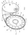
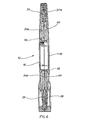
- Figs. 1 - 4 illustrate a first embodiment of the eyesight tester according to the invention, whereby one can test for short-sightedness and long-sightedness, for example.
- the eyesight tester according to the two following embodiments in which each support half has two wheels arranged thereto with lenses of different powers, one may for example test for aberration of cornea.
- the reference numerals 10 and 12 indicate two support halves hinged together, each comprising a pair of cover elements 14, 16 and 18, 20 overlapping in pairs.
- This shared hinge structure is defined by 22. All these main parts may be produced from suitable plastic materials.
- the hinge may have two stable positions, one open active position, Figs. 1 and 2, and a folded, inactive position, Fig. 4. In its folded inactive position the support structure of the eyesight tester occupies minimal space and is less vulnerable than in its unfolded condition.
- each support half 10, 12 Between the two cover elements 14, 16 and 18, 20 of each support half 10, 12 are rotatably supported wheels 24 and 24, see in particular Fig. 2, projecting from the cover elements 14, 16 and 18, 20, respectively, in the radial direction by a wheel circumference portion 24a and 26a, respectively, through a recess 28, 30 in the common circumferential area of the cover elements overlapping in pairs.
- Each wheel 24 or 26 has the form of an annular specially profiled disc, Fig. 3, whose inner circular circumferential surface is formed with a circular groove 31, which is engaged, in a glidingly displaceablemanner, by a complementarily formed bulb 32 on an adjacent internal hub, Figs. 3 and 8.
- Lenses 34 differing in refractive powers are distributed along an imaginary circle which is centric with respect to the axis of rotation 24A, 26A of the wheel 24, 26.
- Each support half 10, 12 has an eye piece, indicated by 36 and 38, respectively. Fittings around each eye piece are exclusively of an aesthetic nature and without any technical significance to the present invention, each hole 36, 38 representing the most suitable point on the eyesight tester for placing each eye in the testing of eyesight right opposite, for example individually, a number of lenses 34, 34a whose powers/refractive powers differ from one another, so that each set of lenses of one wheel may comprise lenses of steps of 0,5 dioptres. From 0 to -5 dioptres on one half of the wheel - 180° - and from 0 to +5 dioptres on the other half of the wheel, all together for example 22 lenses distributed along the circumference of one wheel.
- the lenses 34, 34a should conveniently be embedded in the respective wheels 24 or 26, see in particular Fig. 3. Both the wheel 24 and the lenses may possibly be moulded of the same material.
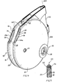
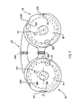
- a common feature of two further embodiments of the invention consists in the use of two overlapping wheels 24, 24b in each support half of the eyesight tester according to the invention, wherein the two wheels 24, 24b are independently rotatable relative to one another, and - in Figs. 5 and 6 - arranged centrically to one another.
- two lenses 34 - one from each of the two wheels - may be brought to overlap one another within the eye piece 36, for example with the purpose of testing for aberration of the cornea.
- the two wheels 24, 24b which partially overlap one another within one support half of the eyesight tester, are supported eccentric to each other. This provides advantages in the advancing of one wheel relative to the other by the projecting outer circumferential portion of the respective wheel, in that by this eccentric positioning of the wheels, it will be more difficult to mistake their projecting peripheral operating portions, where recesses are formed in the common circumferential region of the pair of cover elements.
- one lens distribution circle will have to intersect the other (eccentric) circle within the respective eye piece 36, 38.
- one wheel may comprise 22 lenses 34, 34a, while the other wheel may be used to test for example for aberration of the corneas, wherein the refractive power of the lenses may vary from 0 to -5 dioptres with steps of for example 0,25 dioptres.
- the relevant lens wheel is turned until the lens, for example 34A, through which one can have the sharpest vision with the eye positioned at the eye piece 36 (or 38).
- the lens power is read off in the hole 40 (or 41) and may be for example -3 for the lens 34a in the eye piece 36.
- the wheel surface 24, which appears from Fig. 2 will be marked.with the lens power values (such as -3 for 34a), which will appear in the small hole 40 (or 41) while, at the same time, the associated lens 34 is located in the eye piece 36 (or 38).
- the embodiment of the eyesight tester according to Figs. 5 and 6 or Figs. 7 and 8 may be constructed for a way of operating, in which the uppermost wheels 24b, 26b are first set to power 0, after which the lowermost wheels 24, 26 are set to the best power first, corrections possibly being made later to test for aberration of the cornea, by adjusting the uppermost wheels 24b, 26b until vision is optimal. Then the result is read off.
- the eyesight tester may possibly be manipulated by the user, who may spend a very long time carrying out the test, which may also be extended to comprise testing of depth vision, colour vision etc.
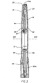
- Fig. 9 which is a radial sectional view along the line IX-IX in Fig. 4, there is shown a possible ability of the circumference of each of the support halves 10, 12 to rotate relative to the hinge 22, along a suitable continuous part of the circumference of said support halves.
- the two eye pieces/oculars 36, 38 may be brought to be mutually approaching/separating, for an eyesight tester to be suited for several persons of different eye distances.
- An elongate, curved projecting strip 44 extending along each connecting edge of the hinge blades, has an outer thickened part, which displaceably engages, with friction, a radially inner groove portion of a complementary cross-sectional form, of a groove 46 with the cross-sectional shape of an inverted T, formed between a pair of cooperating cover elements 18, 20, at the circumference thereof.
- the groove 46 may have closed ends.
- the projecting strip 44 of the hinge 22 engaging the groove 46 cannot fall out of the groove 46, and the rotatable connection between the hinge on the one hand and each of the support halves 10, 12 on the other hand is thus permanently connected.
- the ocular/eye piece 38 will move away from the hinge axis 22A. So would the ocular 36 of the pair of cover elements 14,16 by anti-clockwise rotation, in the unfolded position, Fig. 1, resulting in an increased distance between the oculars 36, 38.
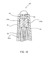
- Fig. 10 shows a partial cross-sectional view on a larger scale, corresponding to Fig. 9, in which the support half 14,16 encloses two coaxial lens wheels 24, 24b, and in which the lenses, which are indicated by 34, 34a, are embedded in the respective wheel 24, 24b near the wheel circumference.
- the joined circumferential portions of the cover elements 14, 16 are formed with a groove 46 with the cross-sectional shape of an inverted T, which is displaceably engaged by a complementarily shaped portion 44 of the hinge 22.
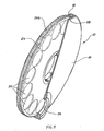
- each support half 10 there are arranged, in each support half 10, 12, two wheels 24, 24b and 26, 26b, the wheels of each pair of wheels being arranged eccentric to one another.
- each support half 10 and 12 are formed with two edge recesses, 28,28b and 30,30b, respectively, at their circumferences.
- Each wheel 24, 24b, 26, 26b is provided with a number of radially projecting tongues, projections 48, 50, 52, 54, of which one can be seen in each edge recess, 28, 28b, 30, 30b, respectively, each one carrying an indication of lens powers, indicated only for the projection 50, indicating -3, corresponding to one of the lenses located in the eye piece 36.
- Fig. 12 in a front view corresponding to Figs. 7 and 11, is visualized a further embodiment in which there are formed, in each front cover element 14, 18, two through holes 40, 40a and 41, 41a to disclose the lens power indications on the outward wheel surface, corresponding to the mutually overlapping lenses of two wheels, made visible simultaneously in the eye pieces 36, 38.
- the front wheels 24b and 26b must be transparent, either entirely or in the areas of the imaginary circular paths of distribution of the rear wheels 24 and 26, along which are placed the lens power indications of the wheels last mentioned, and which must not be covered and made invisible by the front wheels 24b and 26b.
Landscapes
- Life Sciences & Earth Sciences (AREA)
- Health & Medical Sciences (AREA)
- Medical Informatics (AREA)
- Biophysics (AREA)
- Ophthalmology & Optometry (AREA)
- Engineering & Computer Science (AREA)
- Biomedical Technology (AREA)
- Heart & Thoracic Surgery (AREA)
- Physics & Mathematics (AREA)
- Molecular Biology (AREA)
- Surgery (AREA)
- Animal Behavior & Ethology (AREA)
- General Health & Medical Sciences (AREA)
- Public Health (AREA)
- Veterinary Medicine (AREA)
- Eyeglasses (AREA)
- Eye Examination Apparatus (AREA)
Claims (5)
- Vorrichtung zur Sehkraftprüfung zum Feststellen von Kurzsichtigkeit oder Weitsichtigkeit mit einer Anzahl von Linsen (34, 34a) mit unterschiedlichen Brechkräften, die durch eine Okularvorrichtung (36; 38) vor dem zu prüfenden Auge in Position gebracht werden können, wobei die Vorrichtung ferner einen Träger mit zwei Trägerteilen (10, 12) umfaßt, die jeweils zum drehbaren Abstützen mindestens eines Rades (24, 24b, 26, 26b) mit einem vorzugsweise runden Umfang ausgebildet sind, entlang dessen die Linsen (34, 34a) entlang mindestens eines imaginären. Kreises verteilt angeordnet sind, wobei die Okularvorrichtung (36; 38) auf dem imaginären Kreis so angeordnet ist, daß eine Linse (34, 34a) eines jeweiligen Rades (24, 24b, 26, 26b) auf einmal innerhalb der Okularvorrichtung (36; 38) durch stufenweise Drehung des Rades positionierbar ist, und eine Einrichtung, um eine Linsenbrechkraftangabe am Rad entsprechend der Linse (34a) oder einander überlappenden Linsen, die gleichzeitig innerhalb des Okulars (36; 38) erscheinen, sichtbar zu machen, wobei die Linsenbrechkraftangabe durch das jeweilige Rad vorzugsweise entlang imaginärer Kreise verteilt getragen ist, dadurch gekennzeichnet, daß die zwei Teile (10, 12) des Sehkraftprüfgerätträgers durch ein Gelenk (22) gelenkig miteinander gelagert sind, welches eine solche Biegsamkeit aufweist, daß es ermöglicht, daß der Träger um die Gelenkachse eingeklappt wird, um eine doppelt eingeklappte, unwirksame Position zu belegen, in der die zwei Trägerteile (10, 12) einander überlappen.
- Vorrichtung nach Anspruch 1, dadurch gekennzeichnet, daß der Umfang des Rades (24, 24b, 26, 26b) mit radial gerichteten Vorsprüngen (48, 50, 52, 54) versehen ist, die jeweils eine Linsenbrechkraftangabe tragen, wobei die Linsenbrechkraftangaben in Kantenaussparungen (28, 28b, 30, 30b) gleichzeitig mit mindestens einer Linse, die im Okular (36, 38) erscheint, erscheinen.
- Vorrichtung nach Anspruch 2, dadurch gekennzeichnet, daß das Gelenk (22) zwei stabile Positionen aufweist, eine offene Position, in der seine zwei Gelenkteile in der Fortsetzung zueinander orientiert sind, entsprechend der Verwendungsposition des Sehkraftprüfgeräts, und eine eingeklappte Position, in der die Gelenkteile, im Wesentlichen einander überlappen, und wobei in der letzteren Gelenkposition die Trägerteile (10 und 12) auch einander im Wesentlichen überlappen.
- Vorrichtung nach Anspruch 1, dadurch gekennzeichnet, daß jeder Trägerteil (10, 12) zumindest über einem Teil seines Umfangs mit einer. Nut (46) ausgebildet ist, die nach außen in einer radialen Richtung offen ist, wobei die Nut (46) an ihrem Boden eine größere Breite aufweist als an ihrer Öffnung am Umfang und darin verschiebbar einen entsprechend geformten Vorsprung der benachbarten Kante des Gelenks (22) aufnimmt, das die Trägerteile (10, 12) einklappbar miteinander verbindet.
- Vorrichtung nach Anspruch 1, dadurch gekennzeichnet, daß jeder Trägerteil (10. 12) mit dem Gelenk (22) drehbar verbunden ist, wobei die Anordnung derart ist, daß der Abstand zwischen den Okularen (36, 38) verändert werden kann.
Applications Claiming Priority (3)
| Application Number | Priority Date | Filing Date | Title |
|---|---|---|---|
| NO19990588A NO311825B1 (no) | 1999-02-09 | 1999-02-09 | Anordning for bruk ved testing av synet |
| NO990588 | 1999-02-09 | ||
| PCT/NO2000/000036 WO2000047106A2 (en) | 1999-02-09 | 2000-02-03 | Device for use in eyesight testing |
Publications (2)
| Publication Number | Publication Date |
|---|---|
| EP1154716A2 EP1154716A2 (de) | 2001-11-21 |
| EP1154716B1 true EP1154716B1 (de) | 2005-12-07 |
Family
ID=19902932
Family Applications (1)
| Application Number | Title | Priority Date | Filing Date |
|---|---|---|---|
| EP00904146A Expired - Lifetime EP1154716B1 (de) | 1999-02-09 | 2000-02-03 | Vorrichtung zum gebrauch bei der überprüfung des sehvermögens |
Country Status (18)
| Country | Link |
|---|---|
| US (1) | US6659612B1 (de) |
| EP (1) | EP1154716B1 (de) |
| JP (1) | JP4393714B2 (de) |
| CN (1) | CN1197516C (de) |
| AR (1) | AR022548A1 (de) |
| AT (1) | ATE311808T1 (de) |
| AU (1) | AU763606B2 (de) |
| BR (1) | BR0008113A (de) |
| CA (1) | CA2359908C (de) |
| CO (1) | CO5221119A1 (de) |
| DE (1) | DE60024584T2 (de) |
| ES (1) | ES2254138T3 (de) |
| HK (1) | HK1044696B (de) |
| ID (1) | ID29960A (de) |
| MX (1) | MXPA01008042A (de) |
| MY (1) | MY122653A (de) |
| NO (1) | NO311825B1 (de) |
| WO (1) | WO2000047106A2 (de) |
Families Citing this family (10)
| Publication number | Priority date | Publication date | Assignee | Title |
|---|---|---|---|---|
| JP2004208705A (ja) | 2002-12-26 | 2004-07-29 | Nidek Co Ltd | 検眼装置 |
| US20080241782A1 (en) * | 2007-03-30 | 2008-10-02 | Norbert Abels | Two-part self-ligating orthodontic bracket having lateral guiding mechanism |
| KR102290818B1 (ko) * | 2012-07-04 | 2021-08-17 | 가부시키가이샤 니데크 | 안과 장치 제어 방법 |
| FR3016705B1 (fr) * | 2014-01-20 | 2017-06-16 | Essilor Int | Systeme de compensation visuelle et dispositif binoculaire d'optometrie |
| FR3019459B1 (fr) * | 2014-04-08 | 2016-04-22 | Essilor Int | Lunettes de compensation visuelle et procede de refraction subjective d'un individu portant ces lunettes |
| CN104644118A (zh) * | 2014-05-30 | 2015-05-27 | 融水苗族自治县人民医院 | 视力检测仪 |
| KR101663765B1 (ko) | 2015-02-10 | 2016-10-07 | 박성용 | 모양체근 훈련 장치 |
| CN106125311A (zh) * | 2016-08-31 | 2016-11-16 | 安徽协创物联网技术有限公司 | 一种具有多种视力调节的vr眼镜 |
| CN109700425B (zh) * | 2018-12-27 | 2021-07-30 | 山东百鸣控股集团有限公司 | 一种色盲测试设备 |
| WO2021113910A1 (en) | 2019-12-09 | 2021-06-17 | 4ize Pty Ltd | Portable sight testing apparatus |
Family Cites Families (9)
| Publication number | Priority date | Publication date | Assignee | Title |
|---|---|---|---|---|
| DE76618C (de) * | Dr. F. KNAUER, Augenarzt, in Berlin N.W., Rathenowerstrafse 83 | Augenspiegel mit selbstthätiger Summirung der combinirten Linsenwerthe | ||
| US1384252A (en) * | 1920-05-29 | 1921-07-12 | James F Giddens | Eye-testing device |
| US2888856A (en) * | 1956-01-13 | 1959-06-02 | Marly Pierre Andre | Ophthalmological instrument for the examination of the eyesight |
| FR2481916A1 (fr) * | 1980-05-08 | 1981-11-13 | Loupes Hautes Performances | Dispositif optique correcteur provisoire permettant le choix d'une monture nue |
| US4549792A (en) * | 1982-03-26 | 1985-10-29 | Optyl Eyewear Fashion International Corporation | Adjustable nose piece and incorporating sunglasses |
| WO1995019133A1 (en) * | 1994-01-12 | 1995-07-20 | Kelman Charles D | Lens selection system |
| US5486879A (en) * | 1994-06-06 | 1996-01-23 | Barnett; Mark | Portable, public use reading glasses eye tester |
| GB2293023B (en) * | 1994-09-02 | 1998-03-11 | Hatu Ico Spa | Device for selecting spectacle lenses |
| US6022105A (en) * | 1999-04-10 | 2000-02-08 | Lin; David Gu | Detachable sunglasses with adjustable bridge |
-
1999
- 1999-02-09 NO NO19990588A patent/NO311825B1/no not_active IP Right Cessation
-
2000
- 2000-02-03 AT AT00904146T patent/ATE311808T1/de not_active IP Right Cessation
- 2000-02-03 JP JP2000598061A patent/JP4393714B2/ja not_active Expired - Fee Related
- 2000-02-03 CN CNB008036098A patent/CN1197516C/zh not_active Expired - Fee Related
- 2000-02-03 BR BR0008113-2A patent/BR0008113A/pt not_active IP Right Cessation
- 2000-02-03 AU AU25816/00A patent/AU763606B2/en not_active Ceased
- 2000-02-03 EP EP00904146A patent/EP1154716B1/de not_active Expired - Lifetime
- 2000-02-03 MX MXPA01008042A patent/MXPA01008042A/es not_active IP Right Cessation
- 2000-02-03 ES ES00904146T patent/ES2254138T3/es not_active Expired - Lifetime
- 2000-02-03 CA CA002359908A patent/CA2359908C/en not_active Expired - Fee Related
- 2000-02-03 ID IDW00200101700Q patent/ID29960A/id unknown
- 2000-02-03 WO PCT/NO2000/000036 patent/WO2000047106A2/en active IP Right Grant
- 2000-02-03 DE DE60024584T patent/DE60024584T2/de not_active Expired - Lifetime
- 2000-02-03 US US09/913,210 patent/US6659612B1/en not_active Expired - Fee Related
- 2000-02-08 MY MYPI20000420A patent/MY122653A/en unknown
- 2000-02-09 CO CO00008335A patent/CO5221119A1/es not_active Application Discontinuation
- 2000-02-09 AR ARP000100554A patent/AR022548A1/es active IP Right Grant
-
2002
- 2002-08-30 HK HK02106420.5A patent/HK1044696B/zh not_active IP Right Cessation
Also Published As
| Publication number | Publication date |
|---|---|
| NO990588D0 (no) | 1999-02-09 |
| WO2000047106A2 (en) | 2000-08-17 |
| HK1044696B (zh) | 2005-09-09 |
| MY122653A (en) | 2006-04-29 |
| AR022548A1 (es) | 2002-09-04 |
| NO311825B1 (no) | 2002-02-04 |
| AU763606B2 (en) | 2003-07-31 |
| ID29960A (id) | 2001-10-25 |
| EP1154716A2 (de) | 2001-11-21 |
| CO5221119A1 (es) | 2002-11-28 |
| HK1044696A1 (en) | 2002-11-01 |
| WO2000047106A3 (en) | 2000-12-07 |
| BR0008113A (pt) | 2001-11-06 |
| ATE311808T1 (de) | 2005-12-15 |
| DE60024584T2 (de) | 2006-08-31 |
| JP4393714B2 (ja) | 2010-01-06 |
| DE60024584D1 (de) | 2006-01-12 |
| CN1339952A (zh) | 2002-03-13 |
| MXPA01008042A (es) | 2002-04-24 |
| AU2581600A (en) | 2000-08-29 |
| CA2359908C (en) | 2008-08-05 |
| CA2359908A1 (en) | 2000-08-17 |
| JP2002536101A (ja) | 2002-10-29 |
| NO990588L (no) | 2000-08-10 |
| CN1197516C (zh) | 2005-04-20 |
| US6659612B1 (en) | 2003-12-09 |
| ES2254138T3 (es) | 2006-06-16 |
Similar Documents
| Publication | Publication Date | Title |
|---|---|---|
| EP1154716B1 (de) | Vorrichtung zum gebrauch bei der überprüfung des sehvermögens | |
| US7481535B2 (en) | Complete autorefractor system in an ultra-compact package | |
| US5757460A (en) | Combination ophthalmic device | |
| US7878654B2 (en) | Multi-purpose ophthalmological apparatus | |
| US3205505A (en) | Vision-testing apparatus having angularly spaced viewing paths for viewing two concentric series of testing charts | |
| US4758080A (en) | Pointspread retinoscope | |
| US7357505B2 (en) | Device for self-measurement of interpupillary distance | |
| US4643546A (en) | Ophthalmoscope with automatic lens shifting mechanism | |
| KR101490674B1 (ko) | 튜너블 렌즈를 이용하는 검안용 굴절력 측정 장치 | |
| CN203280363U (zh) | 一种小瞳检影的辅助柱镜 | |
| US5953101A (en) | Vision collimator | |
| US20040130679A1 (en) | Optometric apparatus | |
| Takabayashi et al. | Influence of decorative lenses on higher-order wavefront aberrations | |
| JPS6111089B2 (de) | ||
| GB2293023A (en) | Device for selecting spectacle lenses | |
| JP4177515B2 (ja) | 両眼視機能検査装置 | |
| US1130106A (en) | Optical instrument. | |
| US2442750A (en) | Head mirror device | |
| JPS6243532Y2 (de) | ||
| JPS6220808B2 (de) | ||
| JPS6155375B2 (de) | ||
| Lang | Optical systems for the refractive examination of the eye | |
| Lantz et al. | A comparative evaluation of different models and brands of direct ophthalmoscopes and retinoscopes | |
| Krill | Clinical aspects of night vision(Reduced illumination effects on visual acuity, color vision, dark adaptation, accommodation, visual fields and glare) | |
| Boardman et al. | The Relationship Between Corneal Contour as Measured With a Keratometer and Fluorescein Patterns, in the Fitting of Micro‐Corneal Lenses |
Legal Events
| Date | Code | Title | Description |
|---|---|---|---|
| PUAI | Public reference made under article 153(3) epc to a published international application that has entered the european phase |
Free format text: ORIGINAL CODE: 0009012 |
|
| 17P | Request for examination filed |
Effective date: 20010903 |
|
| AK | Designated contracting states |
Kind code of ref document: A2 Designated state(s): AT BE CH CY DE DK ES FI FR GB GR IE IT LI LU MC NL PT SE |
|
| AX | Request for extension of the european patent |
Free format text: AL;LT;LV;MK;RO;SI |
|
| GRAP | Despatch of communication of intention to grant a patent |
Free format text: ORIGINAL CODE: EPIDOSNIGR1 |
|
| GRAS | Grant fee paid |
Free format text: ORIGINAL CODE: EPIDOSNIGR3 |
|
| GRAA | (expected) grant |
Free format text: ORIGINAL CODE: 0009210 |
|
| AK | Designated contracting states |
Kind code of ref document: B1 Designated state(s): AT BE CH CY DE DK ES FI FR GB GR IE IT LI LU MC NL PT SE |
|
| PG25 | Lapsed in a contracting state [announced via postgrant information from national office to epo] |
Ref country code: AT Free format text: LAPSE BECAUSE OF FAILURE TO SUBMIT A TRANSLATION OF THE DESCRIPTION OR TO PAY THE FEE WITHIN THE PRESCRIBED TIME-LIMIT Effective date: 20051207 Ref country code: FI Free format text: LAPSE BECAUSE OF FAILURE TO SUBMIT A TRANSLATION OF THE DESCRIPTION OR TO PAY THE FEE WITHIN THE PRESCRIBED TIME-LIMIT Effective date: 20051207 |
|
| REG | Reference to a national code |
Ref country code: GB Ref legal event code: FG4D |
|
| REG | Reference to a national code |
Ref country code: CH Ref legal event code: EP |
|
| REG | Reference to a national code |
Ref country code: IE Ref legal event code: FG4D |
|
| REF | Corresponds to: |
Ref document number: 60024584 Country of ref document: DE Date of ref document: 20060112 Kind code of ref document: P |
|
| PG25 | Lapsed in a contracting state [announced via postgrant information from national office to epo] |
Ref country code: LU Free format text: LAPSE BECAUSE OF NON-PAYMENT OF DUE FEES Effective date: 20060228 Ref country code: MC Free format text: LAPSE BECAUSE OF NON-PAYMENT OF DUE FEES Effective date: 20060228 |
|
| PG25 | Lapsed in a contracting state [announced via postgrant information from national office to epo] |
Ref country code: SE Free format text: LAPSE BECAUSE OF FAILURE TO SUBMIT A TRANSLATION OF THE DESCRIPTION OR TO PAY THE FEE WITHIN THE PRESCRIBED TIME-LIMIT Effective date: 20060307 Ref country code: DK Free format text: LAPSE BECAUSE OF FAILURE TO SUBMIT A TRANSLATION OF THE DESCRIPTION OR TO PAY THE FEE WITHIN THE PRESCRIBED TIME-LIMIT Effective date: 20060307 |
|
| REG | Reference to a national code |
Ref country code: CH Ref legal event code: NV Representative=s name: ISLER & PEDRAZZINI AG |
|
| REG | Reference to a national code |
Ref country code: GR Ref legal event code: EP Ref document number: 20060400849 Country of ref document: GR |
|
| REG | Reference to a national code |
Ref country code: ES Ref legal event code: FG2A Ref document number: 2254138 Country of ref document: ES Kind code of ref document: T3 |
|
| ET | Fr: translation filed | ||
| PLBE | No opposition filed within time limit |
Free format text: ORIGINAL CODE: 0009261 |
|
| STAA | Information on the status of an ep patent application or granted ep patent |
Free format text: STATUS: NO OPPOSITION FILED WITHIN TIME LIMIT |
|
| 26N | No opposition filed |
Effective date: 20060908 |
|
| REG | Reference to a national code |
Ref country code: CH Ref legal event code: PCAR Free format text: ISLER & PEDRAZZINI AG;POSTFACH 1772;8027 ZUERICH (CH) |
|
| PG25 | Lapsed in a contracting state [announced via postgrant information from national office to epo] |
Ref country code: GR Free format text: LAPSE BECAUSE OF NON-PAYMENT OF DUE FEES Effective date: 20060308 |
|
| PG25 | Lapsed in a contracting state [announced via postgrant information from national office to epo] |
Ref country code: CY Free format text: LAPSE BECAUSE OF FAILURE TO SUBMIT A TRANSLATION OF THE DESCRIPTION OR TO PAY THE FEE WITHIN THE PRESCRIBED TIME-LIMIT Effective date: 20051207 |
|
| PG25 | Lapsed in a contracting state [announced via postgrant information from national office to epo] |
Ref country code: IT Free format text: LAPSE BECAUSE OF NON-PAYMENT OF DUE FEES Effective date: 20080203 |
|
| PGFP | Annual fee paid to national office [announced via postgrant information from national office to epo] |
Ref country code: CH Payment date: 20090828 Year of fee payment: 10 |
|
| PGFP | Annual fee paid to national office [announced via postgrant information from national office to epo] |
Ref country code: IE Payment date: 20100131 Year of fee payment: 11 Ref country code: PT Payment date: 20100131 Year of fee payment: 11 |
|
| PGFP | Annual fee paid to national office [announced via postgrant information from national office to epo] |
Ref country code: FR Payment date: 20100304 Year of fee payment: 11 |
|
| PGFP | Annual fee paid to national office [announced via postgrant information from national office to epo] |
Ref country code: GB Payment date: 20100204 Year of fee payment: 11 Ref country code: DE Payment date: 20100303 Year of fee payment: 11 |
|
| PGFP | Annual fee paid to national office [announced via postgrant information from national office to epo] |
Ref country code: NL Payment date: 20100228 Year of fee payment: 11 |
|
| REG | Reference to a national code |
Ref country code: CH Ref legal event code: PL |
|
| PG25 | Lapsed in a contracting state [announced via postgrant information from national office to epo] |
Ref country code: CH Free format text: LAPSE BECAUSE OF NON-PAYMENT OF DUE FEES Effective date: 20100228 Ref country code: LI Free format text: LAPSE BECAUSE OF NON-PAYMENT OF DUE FEES Effective date: 20100228 |
|
| PGFP | Annual fee paid to national office [announced via postgrant information from national office to epo] |
Ref country code: BE Payment date: 20100901 Year of fee payment: 11 |
|
| PGFP | Annual fee paid to national office [announced via postgrant information from national office to epo] |
Ref country code: ES Payment date: 20110221 Year of fee payment: 12 Ref country code: IT Payment date: 20110224 Year of fee payment: 12 |
|
| PGRI | Patent reinstated in contracting state [announced from national office to epo] |
Ref country code: IT Effective date: 20110616 |
|
| BERE | Be: lapsed |
Owner name: *STANGELAND ROLF Effective date: 20110228 |
|
| REG | Reference to a national code |
Ref country code: NL Ref legal event code: V1 Effective date: 20110901 |
|
| GBPC | Gb: european patent ceased through non-payment of renewal fee |
Effective date: 20110203 |
|
| PG25 | Lapsed in a contracting state [announced via postgrant information from national office to epo] |
Ref country code: PT Free format text: LAPSE BECAUSE OF NON-PAYMENT OF DUE FEES Effective date: 20110803 |
|
| REG | Reference to a national code |
Ref country code: FR Ref legal event code: ST Effective date: 20111102 |
|
| REG | Reference to a national code |
Ref country code: IE Ref legal event code: MM4A |
|
| PG25 | Lapsed in a contracting state [announced via postgrant information from national office to epo] |
Ref country code: BE Free format text: LAPSE BECAUSE OF NON-PAYMENT OF DUE FEES Effective date: 20110228 |
|
| PG25 | Lapsed in a contracting state [announced via postgrant information from national office to epo] |
Ref country code: NL Free format text: LAPSE BECAUSE OF NON-PAYMENT OF DUE FEES Effective date: 20110901 |
|
| REG | Reference to a national code |
Ref country code: DE Ref legal event code: R119 Ref document number: 60024584 Country of ref document: DE Effective date: 20110901 |
|
| PG25 | Lapsed in a contracting state [announced via postgrant information from national office to epo] |
Ref country code: IE Free format text: LAPSE BECAUSE OF NON-PAYMENT OF DUE FEES Effective date: 20110203 Ref country code: FR Free format text: LAPSE BECAUSE OF NON-PAYMENT OF DUE FEES Effective date: 20110228 |
|
| PG25 | Lapsed in a contracting state [announced via postgrant information from national office to epo] |
Ref country code: GB Free format text: LAPSE BECAUSE OF NON-PAYMENT OF DUE FEES Effective date: 20110203 |
|
| PG25 | Lapsed in a contracting state [announced via postgrant information from national office to epo] |
Ref country code: IT Free format text: LAPSE BECAUSE OF NON-PAYMENT OF DUE FEES Effective date: 20120203 |
|
| PG25 | Lapsed in a contracting state [announced via postgrant information from national office to epo] |
Ref country code: DE Free format text: LAPSE BECAUSE OF NON-PAYMENT OF DUE FEES Effective date: 20110901 |
|
| REG | Reference to a national code |
Ref country code: ES Ref legal event code: FD2A Effective date: 20130708 |
|
| PG25 | Lapsed in a contracting state [announced via postgrant information from national office to epo] |
Ref country code: ES Free format text: LAPSE BECAUSE OF NON-PAYMENT OF DUE FEES Effective date: 20120204 |