EP1154553A2 - Method and circuit for synchronizing parallel voltage source inverters - Google Patents
Method and circuit for synchronizing parallel voltage source inverters Download PDFInfo
- Publication number
- EP1154553A2 EP1154553A2 EP01302905A EP01302905A EP1154553A2 EP 1154553 A2 EP1154553 A2 EP 1154553A2 EP 01302905 A EP01302905 A EP 01302905A EP 01302905 A EP01302905 A EP 01302905A EP 1154553 A2 EP1154553 A2 EP 1154553A2
- Authority
- EP
- European Patent Office
- Prior art keywords
- signal
- inverter circuit
- phase
- circuit
- sampling
- Prior art date
- Legal status (The legal status is an assumption and is not a legal conclusion. Google has not performed a legal analysis and makes no representation as to the accuracy of the status listed.)
- Granted
Links
Images
Classifications
-
- H—ELECTRICITY
- H02—GENERATION; CONVERSION OR DISTRIBUTION OF ELECTRIC POWER
- H02M—APPARATUS FOR CONVERSION BETWEEN AC AND AC, BETWEEN AC AND DC, OR BETWEEN DC AND DC, AND FOR USE WITH MAINS OR SIMILAR POWER SUPPLY SYSTEMS; CONVERSION OF DC OR AC INPUT POWER INTO SURGE OUTPUT POWER; CONTROL OR REGULATION THEREOF
- H02M7/00—Conversion of AC power input into DC power output; Conversion of DC power input into AC power output
- H02M7/42—Conversion of DC power input into AC power output without possibility of reversal
- H02M7/44—Conversion of DC power input into AC power output without possibility of reversal by static converters
- H02M7/48—Conversion of DC power input into AC power output without possibility of reversal by static converters using discharge tubes with control electrode or semiconductor devices with control electrode
- H02M7/493—Conversion of DC power input into AC power output without possibility of reversal by static converters using discharge tubes with control electrode or semiconductor devices with control electrode the static converters being arranged for operation in parallel
Definitions
- the present invention relates generally to voltage source inverters, and more specifically, to a synchronization circuit for synchronizing the output of parallel voltage source inverters.
- each of the voltage source inverters has an associated phase angle.
- One known problem with placing voltage source inverters in parallel is that if the phase angles are not the same in each of the parallel voltage source inverters, circulating real power between the voltage sources may be developed. Circulating real power reduces the capability and efficiency of the voltage sources. Further, circulating real power may also cause the malfunctioning of the voltage source inverter.
- the parallel voltage source inverters essentially become electrically equivalent by the present invention to eliminate the circulating real power.
- an inverter circuit comprises a synchronization signal source having a first frequency and a first phase.
- a first voltage source inverter circuit is coupled to a load and the synch source.
- the first voltage source inverter circuit comprises a cycle time counter generating a cyclic output signal and a first sampling circuit receiving the cyclic output signal and sampling said cyclic output signal.
- the first sampling circuit generates a magnitude signal and a phase signal in response to said cyclic output signal.
- the first inverter circuit generates an output signal having a first phase in response to the magnitude signal and the phase signal.
- a second voltage source inverter circuit is coupled to the load in parallel with the first voltage source inverter and to the synch signal source.
- the second voltage source inverter circuit has a second cycle time counter generating a second cyclic output signal.
- the second sampling circuit receives the second cyclic output signal and samples the second cyclic output signal.
- the second sampling circuit generates a second magnitude signal and a second phase signal in response to the cyclic output signal.
- the second phase signal and the first phase signal are substantially synchronised.
- a method for generating a voltage signal using a first inverter circuit in parallel with the second inverter circuit comprises the steps of:
- a sawtooth generator may be used to generate the cyclic output signal that represents the phase angle. This eliminates the usually strict requirement that the updating rate of each of the voltage source inverters must be the same and that the updating cycle must be synchronized for the phase angle synchronization among the voltage source inverters.
- Another advantage of the invention is that the fundamental operating frequency and the sampling frequency of the microprocessor do not need strict synchronization.
- Another advantage of the invention is that no analog-to-digital conversion is required between the microcontroller and the sawtooth wave generator.
- the synchronous signal source is digital which has much better noise immunity than analog signals. Also, the digital signal is based on a relatively low frequency and thus the bandwidth requirements for transmission among the parallel voltage source inverters is low.
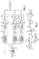
- an inverter circuit 10 has a synchronization (synch) signal source 12 coupled to a plurality of voltage source inverter circuits (VSI 1, VSI n-1, and VSI n). Although three voltage source inverter circuits (VSI) are illustrated, various numbers of voltage source inverter circuits may be used depending on the output power to be provided as would be evident to those skilled in the art.
- the output of each voltage source inverter circuit VSI 1, VSI n-1, and VSI n is coupled to a common load 14.
- Synch signal source 12 is illustrated as a square wave generator. However, those skilled in the art would recognize that other types of synch signal sources may be used. Synch signal source 12 has a fundamental operating frequency input 16. A suitable fundamental operating frequency is a relatively low frequency, e.g., preferably about 50 or 60 Hz. The preferred fundamental operating frequency is the frequency provided through the connection to the mains power companies.
- the synch signal source 12 generates a synch signal represented by reference numeral 18 through an output 20.
- the synch signal 18 has a first frequency corresponding to the fundamental operating frequency input and a phase also corresponding to the fundamental operating frequency input.
- a square wave generator is used as the synch signal source. The square wave is a digital signal and is consequently less susceptible to noise during transmission to the VSIs.
- Each VSI has a timer counter 22 such as a sawtooth wave generator.
- Timer counter 22 generates a cyclic output signal 24 which has a magnitude corresponding to a count of the cycle time of the square wave.
- the cyclic output signal 24 may, for example, correspond to the time since the last rising edge of the synch signal square waves.
- the timer counter 22 converts the square wave synch signal 18 into cyclic output signal 24, which is a sawtooth wave.
- the frequency of the sawtooth wave is the same as the synch signal.
- the sawtooth cyclic output signal 24 also has the same phase as the square wave signal.
- a microprocessor 26 is used to sample the cyclic output signal 24.
- the sampling frequency should be much higher than the synchronization signal frequency of 50 to 60 Hz.
- a suitable range of the sampling frequency is between about 2,000 and 20,000 Hz.
- the sample by the microprocessor of the cyclic output signal 24 corresponds to a time elapsed from the previous rising edge of the phase synch signal.
- the microprocessor has two outputs; a magnitude output 28 and a phase angle output 30.
- the phase angle and the magnitude are coupled to an inverter 32.
- Inverter 32 provides a synchronized signal to load 14 corresponding to V m *Sin ⁇ .
- the phase angles of the outputs of each VSI may be synchronized.
- Timer counter 22 has a time counter 34 that is coupled to a time source such as a clock 36 and to square wave generator 10 for receiving synch signal 18.
- the output of time counter 34 is a measurement of time from the last rising edge of the synch signal 18.
- the cyclic output signal 24 starts at zero upon a rising edge of the synch signal and increases until a new rising edge is presented.
- Clear logic circuit 35 monitors the synch signal 18 and resets time counter 34 upon the rising edge. Of course, other triggers such as a falling edge may be used for resetting. As long as a consistent portion of synch signal 18 is monitored, the phase of the cyclic output signal 24 is the same as the phase of synch signal 18.
- the microprocessor 26 is coupled to gate 40 for receiving cyclic output signal 24.
- Gate 40 is coupled to a sampling line 42 of microprocessor 26 to control the sampling of the cyclic output signal 24. Because the magnitude of the cyclic output signal 24 corresponds to the time since the last rising edge, the phase angle of the signal may be calculated by microprocessor 26 using the equation above. Thus, the inverter may then output a common phase angle signal for each of the VSIs.
- the synch signal 18 is derived from a fundamental operating frequency.
- the square wave signal has a first frequency and a first phase angle.
- the time counting circuit 22 calculates the time since the last rising edge of the synch signal. Because this signal directly corresponds to the time since the last rising edge, the phase angle may be derived therefrom.
- the microprocessor 26 samples the cyclic output signal 24 that corresponds to the time and thus the phase of the output of the microprocessor 26 may be set to provide the inverter with the same signal as the other microprocessors provide to the other inverters.
- the output of each of the inverters is synchronized in terms of phase angle and thus real power will not be circulated through the inverter circuit 10.
Landscapes
- Engineering & Computer Science (AREA)
- Power Engineering (AREA)
- Inverter Devices (AREA)
- Power Conversion In General (AREA)
Abstract
Description
Claims (14)
- An inverter circuit comprising:a synch signal source (12) having a first frequency and a first phase;a first voltage source inverter circuit coupled to a load (14) and said synch signal source(12), said first voltage source inverter circuit comprising a cycle time counter (34) generating a first cyclic output signal(24), a first sampling circuit (26,40) receiving and sampling said first cyclic output signal (24) said first sampling circuit (26,40) generating a magnitude signal (28) and a first phase signal (30) in response to said first cyclic output signal;a second voltage source inverter circuit coupled to said load (14) and said synch signal source (12) in parallel with said first voltage source circuit, said second voltage source inverter circuit comprising a second cycle time counter (34) generating a second cyclic output signal (24), a second sampling circuit (26,40) receiving and sampling said second cyclic output signal (24) said second sampling circuit (26,40) generating a magnitude signal (28) and a second phase signal (30) corresponding to said second cyclic output signal, said second phase signal having a phase substantially synchronised with said first output signal.
- An inverter circuit as claimed in claim 1 wherein said first sampling circuit (26,40) comprises a first microprocessor (26) and said second sampling circuit comprises a second microprocessor (26).
- An inverter circuit as claimed in claim 1 wherein each said cycle time counter (34) comprises a triangle wave generator.
- An inverter circuit as claimed in claim 1 wherein each said cycle time counter (34) is coupled to a clock source (36) and said synchronous signal source (12).
- An inverter circuit as claimed in claim 1 wherein each said time counter (34) generates a sawtooth wave signal having a phase corresponding to said synch signal source.
- An inverter circuit as claimed in claim 1 wherein said first sampling circuit (26,40) has a sampling frequency substantially greater than said first frequency.
- An inverter circuit as claimed in claim 1 wherein said sampling frequency is between 2,000 and 20,000 Hz.
- An inverter circuit as claimed in claim 1 wherein said cycle time counter (34) comprises a time counter and a clear logic circuit (35) coupled to said time counter.
- An inverter circuit as claimed in claim 8, further comprising a clock (36) coupled to the time counter (34) , said time counter counting the clock pulses since a clear logic signal from said clear logic circuit (35).
- A method for generating a voltage signal using a first inverter circuit in parallel with a second inverter circuit comprising the steps of:generating a synch signal having a first frequency and a first phase;continuously counting cycle times of the synch signal in a first inverter circuit;sampling a first cycle time from the cycle times at a first sample moment;calculating a first phase angle in response to the first cycle time;generating an output signal from the first inverter circuit having the first phase angle;counting cycle times of the synch signal in a second inverter circuit;sampling a second cycle time at a second sampling moment;calculating a second phase angle in response to said second cycle time;generating a second output signal from said second inverter circuit having a second phase wherein said second phase angle is substantially synchronised with said first phase angle.
- A method as claimed in claim 10 wherein said step of generating a synch signal comprises a step of generating a square wave signal.
- A method as claimed in claim 10 wherein said step of counting a first cycle of the first synch signal comprises the steps of generating a triangle wave having a third frequency and a third phase corresponding to the first frequency and the first phase.
- A method as claimed in claim10 wherein said step of generating a triangle wave comprises counting the time since a rising edge of the synch signal.
- A method as claimed in claim 10 further comprising the step of clearing a timer in response to a rising edge of the synch signal.
Applications Claiming Priority (2)
| Application Number | Priority Date | Filing Date | Title |
|---|---|---|---|
| US567965 | 2000-05-10 | ||
| US09/567,965 US6178103B1 (en) | 2000-05-10 | 2000-05-10 | Method and circuit for synchronizing parallel voltage source inverters |
Publications (3)
| Publication Number | Publication Date |
|---|---|
| EP1154553A2 true EP1154553A2 (en) | 2001-11-14 |
| EP1154553A3 EP1154553A3 (en) | 2003-07-30 |
| EP1154553B1 EP1154553B1 (en) | 2005-06-15 |
Family
ID=24269358
Family Applications (1)
| Application Number | Title | Priority Date | Filing Date |
|---|---|---|---|
| EP01302905A Expired - Lifetime EP1154553B1 (en) | 2000-05-10 | 2001-03-28 | Method and circuit for synchronizing parallel voltage source inverters |
Country Status (3)
| Country | Link |
|---|---|
| US (1) | US6178103B1 (en) |
| EP (1) | EP1154553B1 (en) |
| DE (1) | DE60111453T2 (en) |
Families Citing this family (7)
| Publication number | Priority date | Publication date | Assignee | Title |
|---|---|---|---|---|
| CN1170354C (en) * | 2001-12-25 | 2004-10-06 | 艾默生网络能源有限公司 | Parallelly connected reverse converter system |
| JP2004248377A (en) * | 2003-02-12 | 2004-09-02 | Toyoda Mach Works Ltd | Drive voltage output device and control method thereof |
| FR2910197B1 (en) * | 2006-12-13 | 2009-02-06 | Messier Dowty Sa Sa | POWER SUPPLY WITH TWO INVERTERS IN SERIES FOR ELECTROMECHANICAL ACTUATOR POLYPHASE |
| US9059603B2 (en) * | 2008-12-11 | 2015-06-16 | Sunline Jamaica Limited | Solar powered electrical energy generating device |
| CN102097855B (en) * | 2010-12-28 | 2013-06-05 | 广东易事特电源股份有限公司 | Phase locking method for digitally controlling parallel operation of uninterruptible power supplies |
| JP2015045553A (en) * | 2013-08-28 | 2015-03-12 | 株式会社三社電機製作所 | Secondary battery charge/discharge device equipped with switching power supply |
| CN105656338B (en) * | 2014-11-14 | 2018-08-14 | 比亚迪股份有限公司 | The common-mode voltage suppressing method and inverter system of multiple inverters |
Family Cites Families (14)
| Publication number | Priority date | Publication date | Assignee | Title |
|---|---|---|---|---|
| US3621365A (en) | 1970-08-13 | 1971-11-16 | Garrett Corp | Parallel coupled static inverters |
| US3832622A (en) * | 1973-07-11 | 1974-08-27 | Avionic Instr Inc | Parallel phase lock circuitry for inverters and the like |
| US4171517A (en) | 1977-01-25 | 1979-10-16 | Tokyo Shibaura Electric Company, Limited | Apparatus for synchronization control of a plurality of inverters |
| JPS62147962A (en) | 1985-12-20 | 1987-07-01 | Toshiba Corp | Control unit of inverter |
| JP2685586B2 (en) | 1989-06-30 | 1997-12-03 | 株式会社日立製作所 | Multiple inverter device |
| US5027265A (en) | 1989-12-20 | 1991-06-25 | Sundstrand Corporation | Regulator for stepped-waveform inverter |
| TW198773B (en) | 1991-03-13 | 1993-01-21 | Mitsubishi Electric Machine | |
| US5257180A (en) | 1991-04-22 | 1993-10-26 | Mitsubishi Denki Kabushiki Kaisha | Controlling system for parallel operation of AC output inverters with restrained cross currents |
| TW245848B (en) | 1991-09-18 | 1995-04-21 | Toshiba Kk | |
| JP3226609B2 (en) | 1992-06-24 | 2001-11-05 | 三菱電機株式会社 | Parallel operation control device for power converter |
| EP0600312B1 (en) | 1992-12-03 | 1996-08-21 | Inventio Ag | Method of controlling parallel-connected inverters on the basis of current maximal values |
| US5745356A (en) * | 1996-06-25 | 1998-04-28 | Exide Electronics Corporation | Independent load sharing of AC power systems connected in parallel |
| DE19720948A1 (en) * | 1997-05-17 | 1998-11-19 | Bosch Gmbh Robert | Voltage conversion device |
| US5883797A (en) * | 1997-06-30 | 1999-03-16 | Power Trends, Inc. | Parallel path power supply |
-
2000
- 2000-05-10 US US09/567,965 patent/US6178103B1/en not_active Expired - Lifetime
-
2001
- 2001-03-28 DE DE60111453T patent/DE60111453T2/en not_active Expired - Lifetime
- 2001-03-28 EP EP01302905A patent/EP1154553B1/en not_active Expired - Lifetime
Also Published As
| Publication number | Publication date |
|---|---|
| US6178103B1 (en) | 2001-01-23 |
| DE60111453T2 (en) | 2006-05-18 |
| EP1154553B1 (en) | 2005-06-15 |
| DE60111453D1 (en) | 2005-07-21 |
| EP1154553A3 (en) | 2003-07-30 |
Similar Documents
| Publication | Publication Date | Title |
|---|---|---|
| KR910002118A (en) | High Resolution Sample Clock Generator with DEGLICHER | |
| GB2353156A (en) | Method and apparatus for varying a clock frequency on a phase by phase basis | |
| EP1154553B1 (en) | Method and circuit for synchronizing parallel voltage source inverters | |
| US6005421A (en) | Synchronous delay circuit for generating synchronous delayed signals with short time and frequency multiplying circuit using the same | |
| RU2014707C1 (en) | Equipment for automatic synchronization of synchronous generators | |
| JP4509535B2 (en) | Semiconductor device and control method | |
| EP1618660B1 (en) | Enabling method to prevent glitches in waveform | |
| JP2950351B2 (en) | Pulse signal generation circuit | |
| JPH08221150A (en) | Clock abnormality detector | |
| KR970056136A (en) | System clock generator | |
| CN121036554B (en) | A parallel inverter system and its synchronization method | |
| JPS6039365A (en) | Periodic pulse noise removing deive | |
| KR980006918A (en) | 50% Duty Cycle Data Generator (50% Duty Cycle Data Generator) | |
| JP2004357201A (en) | Pulse signal waveform shaping circuit | |
| SU1030985A1 (en) | Device for detecting reference signal | |
| JP3147129B2 (en) | Timing generator | |
| SU1495905A1 (en) | Device for synchronization of ac generators | |
| JP2665257B2 (en) | Clock transfer circuit | |
| EP0922332B1 (en) | Frequency dividing circuit | |
| KR100206890B1 (en) | Square wave output synchronous circuit | |
| KR0133877Y1 (en) | Circuit for generating synchronization signals | |
| JP3008678B2 (en) | Parallel-serial converter | |
| KR100882725B1 (en) | Synchronous Data Inverter | |
| RU2216812C1 (en) | Frequency difference relay | |
| SU1265983A1 (en) | Pulse discriminator with respect to repetition frequency |
Legal Events
| Date | Code | Title | Description |
|---|---|---|---|
| PUAI | Public reference made under article 153(3) epc to a published international application that has entered the european phase |
Free format text: ORIGINAL CODE: 0009012 |
|
| AK | Designated contracting states |
Kind code of ref document: A2 Designated state(s): AT BE CH CY DE DK ES FI FR GB GR IE IT LI LU MC NL PT SE TR |
|
| AX | Request for extension of the european patent |
Free format text: AL;LT;LV;MK;RO;SI |
|
| PUAL | Search report despatched |
Free format text: ORIGINAL CODE: 0009013 |
|
| AK | Designated contracting states |
Designated state(s): AT BE CH CY DE DK ES FI FR GB GR IE IT LI LU MC NL PT SE TR |
|
| AX | Request for extension of the european patent |
Extension state: AL LT LV MK RO SI |
|
| RIC1 | Information provided on ipc code assigned before grant |
Ipc: 7H 02M 7/48 A |
|
| 17P | Request for examination filed |
Effective date: 20040126 |
|
| RAP1 | Party data changed (applicant data changed or rights of an application transferred) |
Owner name: BALLARD POWER SYSTEMS CORPORATION |
|
| AKX | Designation fees paid |
Designated state(s): DE FR GB |
|
| 17Q | First examination report despatched |
Effective date: 20040324 |
|
| GRAP | Despatch of communication of intention to grant a patent |
Free format text: ORIGINAL CODE: EPIDOSNIGR1 |
|
| GRAS | Grant fee paid |
Free format text: ORIGINAL CODE: EPIDOSNIGR3 |
|
| GRAA | (expected) grant |
Free format text: ORIGINAL CODE: 0009210 |
|
| AK | Designated contracting states |
Kind code of ref document: B1 Designated state(s): DE FR GB |
|
| REG | Reference to a national code |
Ref country code: GB Ref legal event code: FG4D |
|
| REF | Corresponds to: |
Ref document number: 60111453 Country of ref document: DE Date of ref document: 20050721 Kind code of ref document: P |
|
| ET | Fr: translation filed | ||
| PLBE | No opposition filed within time limit |
Free format text: ORIGINAL CODE: 0009261 |
|
| STAA | Information on the status of an ep patent application or granted ep patent |
Free format text: STATUS: NO OPPOSITION FILED WITHIN TIME LIMIT |
|
| 26N | No opposition filed |
Effective date: 20060316 |
|
| REG | Reference to a national code |
Ref country code: FR Ref legal event code: ST Effective date: 20061130 |
|
| REG | Reference to a national code |
Ref country code: GB Ref legal event code: 732E |
|
| PG25 | Lapsed in a contracting state [announced via postgrant information from national office to epo] |
Ref country code: FR Free format text: LAPSE BECAUSE OF NON-PAYMENT OF DUE FEES Effective date: 20060331 |
|
| PGFP | Annual fee paid to national office [announced via postgrant information from national office to epo] |
Ref country code: GB Payment date: 20160321 Year of fee payment: 16 |
|
| PGFP | Annual fee paid to national office [announced via postgrant information from national office to epo] |
Ref country code: DE Payment date: 20160331 Year of fee payment: 16 |
|
| REG | Reference to a national code |
Ref country code: DE Ref legal event code: R119 Ref document number: 60111453 Country of ref document: DE |
|
| GBPC | Gb: european patent ceased through non-payment of renewal fee |
Effective date: 20170328 |
|
| PG25 | Lapsed in a contracting state [announced via postgrant information from national office to epo] |
Ref country code: DE Free format text: LAPSE BECAUSE OF NON-PAYMENT OF DUE FEES Effective date: 20171003 |
|
| PG25 | Lapsed in a contracting state [announced via postgrant information from national office to epo] |
Ref country code: GB Free format text: LAPSE BECAUSE OF NON-PAYMENT OF DUE FEES Effective date: 20170328 |