EP1154450A2 - Electrolyte for electrochemical device - Google Patents
Electrolyte for electrochemical device Download PDFInfo
- Publication number
- EP1154450A2 EP1154450A2 EP01110673A EP01110673A EP1154450A2 EP 1154450 A2 EP1154450 A2 EP 1154450A2 EP 01110673 A EP01110673 A EP 01110673A EP 01110673 A EP01110673 A EP 01110673A EP 1154450 A2 EP1154450 A2 EP 1154450A2
- Authority
- EP
- European Patent Office
- Prior art keywords
- group
- ion
- electrolyte
- halogenated
- alkyl group
- Prior art date
- Legal status (The legal status is an assumption and is not a legal conclusion. Google has not performed a legal analysis and makes no representation as to the accuracy of the status listed.)
- Withdrawn
Links
- 239000003792 electrolyte Substances 0.000 title claims abstract description 54
- 150000004696 coordination complex Chemical class 0.000 claims abstract description 33
- 150000001875 compounds Chemical class 0.000 claims abstract description 32
- 239000008151 electrolyte solution Substances 0.000 claims description 35
- 229910052782 aluminium Inorganic materials 0.000 claims description 32
- 239000000203 mixture Substances 0.000 claims description 30
- 229910001416 lithium ion Inorganic materials 0.000 claims description 28
- 229920000642 polymer Polymers 0.000 claims description 28
- 125000000217 alkyl group Chemical group 0.000 claims description 24
- 239000010416 ion conductor Substances 0.000 claims description 24
- 239000002904 solvent Substances 0.000 claims description 16
- 229910052744 lithium Inorganic materials 0.000 claims description 15
- 125000002023 trifluoromethyl group Chemical group FC(F)(F)* 0.000 claims description 15
- 125000000008 (C1-C10) alkyl group Chemical group 0.000 claims description 14
- WHXSMMKQMYFTQS-UHFFFAOYSA-N Lithium Chemical compound [Li] WHXSMMKQMYFTQS-UHFFFAOYSA-N 0.000 claims description 12
- 239000000010 aprotic solvent Substances 0.000 claims description 11
- 229910052736 halogen Inorganic materials 0.000 claims description 10
- 239000007784 solid electrolyte Substances 0.000 claims description 9
- 125000005842 heteroatom Chemical group 0.000 claims description 8
- 125000001424 substituent group Chemical group 0.000 claims description 8
- 229910052717 sulfur Inorganic materials 0.000 claims description 8
- HBBGRARXTFLTSG-UHFFFAOYSA-N Lithium ion Chemical compound [Li+] HBBGRARXTFLTSG-UHFFFAOYSA-N 0.000 claims description 7
- 125000002947 alkylene group Chemical group 0.000 claims description 7
- 150000002367 halogens Chemical class 0.000 claims description 7
- 229910052760 oxygen Inorganic materials 0.000 claims description 7
- 229910052796 boron Inorganic materials 0.000 claims description 6
- 239000003990 capacitor Substances 0.000 claims description 6
- 229910052698 phosphorus Inorganic materials 0.000 claims description 6
- 125000006832 (C1-C10) alkylene group Chemical group 0.000 claims description 5
- GPRLSGONYQIRFK-UHFFFAOYSA-N hydron Chemical compound [H+] GPRLSGONYQIRFK-UHFFFAOYSA-N 0.000 claims description 5
- 230000000737 periodic effect Effects 0.000 claims description 5
- 125000003118 aryl group Chemical group 0.000 claims description 4
- 239000013522 chelant Substances 0.000 claims description 4
- 229910052727 yttrium Inorganic materials 0.000 claims description 4
- 229910052787 antimony Inorganic materials 0.000 claims description 3
- 229910052785 arsenic Inorganic materials 0.000 claims description 3
- 125000004429 atom Chemical group 0.000 claims description 3
- 229910052802 copper Inorganic materials 0.000 claims description 3
- 229910052733 gallium Inorganic materials 0.000 claims description 3
- 229910052732 germanium Inorganic materials 0.000 claims description 3
- 229910052758 niobium Inorganic materials 0.000 claims description 3
- 229910052710 silicon Inorganic materials 0.000 claims description 3
- 229910052718 tin Inorganic materials 0.000 claims description 3
- 229910052719 titanium Inorganic materials 0.000 claims description 3
- 229910052720 vanadium Inorganic materials 0.000 claims description 3
- 229910052725 zinc Inorganic materials 0.000 claims description 3
- 229910052726 zirconium Inorganic materials 0.000 claims description 3
- 125000000732 arylene group Chemical group 0.000 claims description 2
- 229910021645 metal ion Inorganic materials 0.000 claims description 2
- 150000004010 onium ions Chemical class 0.000 claims description 2
- 229920006395 saturated elastomer Polymers 0.000 claims description 2
- 229910052723 transition metal Inorganic materials 0.000 claims description 2
- 150000003624 transition metals Chemical class 0.000 claims description 2
- 125000005843 halogen group Chemical group 0.000 claims 3
- 125000001453 quaternary ammonium group Chemical group 0.000 claims 1
- 238000012360 testing method Methods 0.000 description 87
- 238000007599 discharging Methods 0.000 description 42
- KMTRUDSVKNLOMY-UHFFFAOYSA-N Ethylene carbonate Chemical compound O=C1OCCO1 KMTRUDSVKNLOMY-UHFFFAOYSA-N 0.000 description 40
- VZSRBBMJRBPUNF-UHFFFAOYSA-N 2-(2,3-dihydro-1H-inden-2-ylamino)-N-[3-oxo-3-(2,4,6,7-tetrahydrotriazolo[4,5-c]pyridin-5-yl)propyl]pyrimidine-5-carboxamide Chemical compound C1C(CC2=CC=CC=C12)NC1=NC=C(C=N1)C(=O)NCCC(N1CC2=C(CC1)NN=N2)=O VZSRBBMJRBPUNF-UHFFFAOYSA-N 0.000 description 34
- 230000007797 corrosion Effects 0.000 description 28
- 238000005260 corrosion Methods 0.000 description 28
- XAGFODPZIPBFFR-UHFFFAOYSA-N aluminium Chemical compound [Al] XAGFODPZIPBFFR-UHFFFAOYSA-N 0.000 description 26
- RIUWBIIVUYSTCN-UHFFFAOYSA-N trilithium borate Chemical class [Li+].[Li+].[Li+].[O-]B([O-])[O-] RIUWBIIVUYSTCN-UHFFFAOYSA-N 0.000 description 22
- WEVYAHXRMPXWCK-UHFFFAOYSA-N Acetonitrile Chemical compound CC#N WEVYAHXRMPXWCK-UHFFFAOYSA-N 0.000 description 21
- 238000007600 charging Methods 0.000 description 21
- 238000010277 constant-current charging Methods 0.000 description 21
- IEJIGPNLZYLLBP-UHFFFAOYSA-N dimethyl carbonate Chemical compound COC(=O)OC IEJIGPNLZYLLBP-UHFFFAOYSA-N 0.000 description 20
- 150000002500 ions Chemical class 0.000 description 18
- OIFBSDVPJOWBCH-UHFFFAOYSA-N Diethyl carbonate Chemical compound CCOC(=O)OCC OIFBSDVPJOWBCH-UHFFFAOYSA-N 0.000 description 13
- -1 ClO4 ion Chemical class 0.000 description 11
- 150000001450 anions Chemical class 0.000 description 11
- 229910013392 LiN(SO2CF3)(SO2C4F9) Inorganic materials 0.000 description 10
- 229910013385 LiN(SO2C2F5)2 Inorganic materials 0.000 description 9
- 229910001290 LiPF6 Inorganic materials 0.000 description 9
- ZMXDDKWLCZADIW-UHFFFAOYSA-N N,N-Dimethylformamide Chemical compound CN(C)C=O ZMXDDKWLCZADIW-UHFFFAOYSA-N 0.000 description 9
- 230000000694 effects Effects 0.000 description 9
- 230000007062 hydrolysis Effects 0.000 description 9
- 238000006460 hydrolysis reaction Methods 0.000 description 9
- 230000000052 comparative effect Effects 0.000 description 8
- QSZMZKBZAYQGRS-UHFFFAOYSA-N lithium;bis(trifluoromethylsulfonyl)azanide Chemical compound [Li+].FC(F)(F)S(=O)(=O)[N-]S(=O)(=O)C(F)(F)F QSZMZKBZAYQGRS-UHFFFAOYSA-N 0.000 description 8
- 239000000243 solution Substances 0.000 description 8
- 239000003125 aqueous solvent Substances 0.000 description 7
- JBTWLSYIZRCDFO-UHFFFAOYSA-N ethyl methyl carbonate Chemical compound CCOC(=O)OC JBTWLSYIZRCDFO-UHFFFAOYSA-N 0.000 description 7
- 239000003446 ligand Substances 0.000 description 7
- RUOJZAUFBMNUDX-UHFFFAOYSA-N propylene carbonate Chemical compound CC1COC(=O)O1 RUOJZAUFBMNUDX-UHFFFAOYSA-N 0.000 description 7
- OKTJSMMVPCPJKN-UHFFFAOYSA-N Carbon Chemical compound [C] OKTJSMMVPCPJKN-UHFFFAOYSA-N 0.000 description 6
- 229910032387 LiCoO2 Inorganic materials 0.000 description 6
- 229910013406 LiN(SO2CF3)2 Inorganic materials 0.000 description 6
- 230000007613 environmental effect Effects 0.000 description 6
- 239000002033 PVDF binder Substances 0.000 description 5
- 150000001768 cations Chemical class 0.000 description 5
- 229910001496 lithium tetrafluoroborate Inorganic materials 0.000 description 5
- 229920002981 polyvinylidene fluoride Polymers 0.000 description 5
- 239000000126 substance Substances 0.000 description 5
- AFCARXCZXQIEQB-UHFFFAOYSA-N N-[3-oxo-3-(2,4,6,7-tetrahydrotriazolo[4,5-c]pyridin-5-yl)propyl]-2-[[3-(trifluoromethoxy)phenyl]methylamino]pyrimidine-5-carboxamide Chemical compound O=C(CCNC(=O)C=1C=NC(=NC=1)NCC1=CC(=CC=C1)OC(F)(F)F)N1CC2=C(CC1)NN=N2 AFCARXCZXQIEQB-UHFFFAOYSA-N 0.000 description 4
- 230000015572 biosynthetic process Effects 0.000 description 4
- RTZKZFJDLAIYFH-UHFFFAOYSA-N ether Chemical group CCOCC RTZKZFJDLAIYFH-UHFFFAOYSA-N 0.000 description 4
- 229910052757 nitrogen Inorganic materials 0.000 description 4
- 238000003786 synthesis reaction Methods 0.000 description 4
- 229910000552 LiCF3SO3 Inorganic materials 0.000 description 3
- NIPNSKYNPDTRPC-UHFFFAOYSA-N N-[2-oxo-2-(2,4,6,7-tetrahydrotriazolo[4,5-c]pyridin-5-yl)ethyl]-2-[[3-(trifluoromethoxy)phenyl]methylamino]pyrimidine-5-carboxamide Chemical compound O=C(CNC(=O)C=1C=NC(=NC=1)NCC1=CC(=CC=C1)OC(F)(F)F)N1CC2=C(CC1)NN=N2 NIPNSKYNPDTRPC-UHFFFAOYSA-N 0.000 description 3
- 229920003171 Poly (ethylene oxide) Polymers 0.000 description 3
- 125000003178 carboxy group Chemical group [H]OC(*)=O 0.000 description 3
- 239000003054 catalyst Substances 0.000 description 3
- 229920001940 conductive polymer Polymers 0.000 description 3
- 238000010494 dissociation reaction Methods 0.000 description 3
- 230000005593 dissociations Effects 0.000 description 3
- 238000001035 drying Methods 0.000 description 3
- 239000011521 glass Substances 0.000 description 3
- 229910052751 metal Inorganic materials 0.000 description 3
- 239000002184 metal Substances 0.000 description 3
- 229910044991 metal oxide Inorganic materials 0.000 description 3
- 150000004706 metal oxides Chemical class 0.000 description 3
- 229910021382 natural graphite Inorganic materials 0.000 description 3
- 239000007773 negative electrode material Substances 0.000 description 3
- 239000007774 positive electrode material Substances 0.000 description 3
- 150000003839 salts Chemical class 0.000 description 3
- HMUNWXXNJPVALC-UHFFFAOYSA-N 1-[4-[2-(2,3-dihydro-1H-inden-2-ylamino)pyrimidin-5-yl]piperazin-1-yl]-2-(2,4,6,7-tetrahydrotriazolo[4,5-c]pyridin-5-yl)ethanone Chemical compound C1C(CC2=CC=CC=C12)NC1=NC=C(C=N1)N1CCN(CC1)C(CN1CC2=C(CC1)NN=N2)=O HMUNWXXNJPVALC-UHFFFAOYSA-N 0.000 description 2
- LDXJRKWFNNFDSA-UHFFFAOYSA-N 2-(2,4,6,7-tetrahydrotriazolo[4,5-c]pyridin-5-yl)-1-[4-[2-[[3-(trifluoromethoxy)phenyl]methylamino]pyrimidin-5-yl]piperazin-1-yl]ethanone Chemical compound C1CN(CC2=NNN=C21)CC(=O)N3CCN(CC3)C4=CN=C(N=C4)NCC5=CC(=CC=C5)OC(F)(F)F LDXJRKWFNNFDSA-UHFFFAOYSA-N 0.000 description 2
- YLZOPXRUQYQQID-UHFFFAOYSA-N 3-(2,4,6,7-tetrahydrotriazolo[4,5-c]pyridin-5-yl)-1-[4-[2-[[3-(trifluoromethoxy)phenyl]methylamino]pyrimidin-5-yl]piperazin-1-yl]propan-1-one Chemical compound N1N=NC=2CN(CCC=21)CCC(=O)N1CCN(CC1)C=1C=NC(=NC=1)NCC1=CC(=CC=C1)OC(F)(F)F YLZOPXRUQYQQID-UHFFFAOYSA-N 0.000 description 2
- YEJRWHAVMIAJKC-UHFFFAOYSA-N 4-Butyrolactone Chemical compound O=C1CCCO1 YEJRWHAVMIAJKC-UHFFFAOYSA-N 0.000 description 2
- 229910017048 AsF6 Inorganic materials 0.000 description 2
- IAZDPXIOMUYVGZ-UHFFFAOYSA-N Dimethylsulphoxide Chemical compound CS(C)=O IAZDPXIOMUYVGZ-UHFFFAOYSA-N 0.000 description 2
- PXGOKWXKJXAPGV-UHFFFAOYSA-N Fluorine Chemical compound FF PXGOKWXKJXAPGV-UHFFFAOYSA-N 0.000 description 2
- 239000002841 Lewis acid Substances 0.000 description 2
- VCUFZILGIRCDQQ-KRWDZBQOSA-N N-[[(5S)-2-oxo-3-(2-oxo-3H-1,3-benzoxazol-6-yl)-1,3-oxazolidin-5-yl]methyl]-2-[[3-(trifluoromethoxy)phenyl]methylamino]pyrimidine-5-carboxamide Chemical group O=C1O[C@H](CN1C1=CC2=C(NC(O2)=O)C=C1)CNC(=O)C=1C=NC(=NC=1)NCC1=CC(=CC=C1)OC(F)(F)F VCUFZILGIRCDQQ-KRWDZBQOSA-N 0.000 description 2
- 239000004698 Polyethylene Substances 0.000 description 2
- WYURNTSHIVDZCO-UHFFFAOYSA-N Tetrahydrofuran Chemical compound C1CCOC1 WYURNTSHIVDZCO-UHFFFAOYSA-N 0.000 description 2
- GWEVSGVZZGPLCZ-UHFFFAOYSA-N Titan oxide Chemical compound O=[Ti]=O GWEVSGVZZGPLCZ-UHFFFAOYSA-N 0.000 description 2
- 239000011230 binding agent Substances 0.000 description 2
- 229910052799 carbon Inorganic materials 0.000 description 2
- 230000008859 change Effects 0.000 description 2
- 229910001914 chlorine tetroxide Inorganic materials 0.000 description 2
- 239000010949 copper Substances 0.000 description 2
- GNTDGMZSJNCJKK-UHFFFAOYSA-N divanadium pentaoxide Chemical compound O=[V](=O)O[V](=O)=O GNTDGMZSJNCJKK-UHFFFAOYSA-N 0.000 description 2
- 229910052731 fluorine Inorganic materials 0.000 description 2
- 239000011737 fluorine Substances 0.000 description 2
- 125000002887 hydroxy group Chemical group [H]O* 0.000 description 2
- 150000007517 lewis acids Chemical class 0.000 description 2
- 229910001540 lithium hexafluoroarsenate(V) Inorganic materials 0.000 description 2
- MHCFAGZWMAWTNR-UHFFFAOYSA-M lithium perchlorate Chemical compound [Li+].[O-]Cl(=O)(=O)=O MHCFAGZWMAWTNR-UHFFFAOYSA-M 0.000 description 2
- 229910001486 lithium perchlorate Inorganic materials 0.000 description 2
- 229910003002 lithium salt Inorganic materials 0.000 description 2
- 159000000002 lithium salts Chemical class 0.000 description 2
- 238000000034 method Methods 0.000 description 2
- JKQOBWVOAYFWKG-UHFFFAOYSA-N molybdenum trioxide Chemical compound O=[Mo](=O)=O JKQOBWVOAYFWKG-UHFFFAOYSA-N 0.000 description 2
- 239000003960 organic solvent Substances 0.000 description 2
- 239000004014 plasticizer Substances 0.000 description 2
- 229920000573 polyethylene Polymers 0.000 description 2
- 239000000843 powder Substances 0.000 description 2
- 230000008569 process Effects 0.000 description 2
- 238000000197 pyrolysis Methods 0.000 description 2
- 239000002002 slurry Substances 0.000 description 2
- 230000002194 synthesizing effect Effects 0.000 description 2
- 239000010936 titanium Substances 0.000 description 2
- XLYOFNOQVPJJNP-UHFFFAOYSA-N water Substances O XLYOFNOQVPJJNP-UHFFFAOYSA-N 0.000 description 2
- 239000011701 zinc Substances 0.000 description 2
- RYHBNJHYFVUHQT-UHFFFAOYSA-N 1,4-Dioxane Chemical compound C1COCCO1 RYHBNJHYFVUHQT-UHFFFAOYSA-N 0.000 description 1
- JWUJQDFVADABEY-UHFFFAOYSA-N 2-methyltetrahydrofuran Chemical compound CC1CCCO1 JWUJQDFVADABEY-UHFFFAOYSA-N 0.000 description 1
- BHPQYMZQTOCNFJ-UHFFFAOYSA-N Calcium cation Chemical compound [Ca+2] BHPQYMZQTOCNFJ-UHFFFAOYSA-N 0.000 description 1
- RYGMFSIKBFXOCR-UHFFFAOYSA-N Copper Chemical compound [Cu] RYGMFSIKBFXOCR-UHFFFAOYSA-N 0.000 description 1
- JPVYNHNXODAKFH-UHFFFAOYSA-N Cu2+ Chemical compound [Cu+2] JPVYNHNXODAKFH-UHFFFAOYSA-N 0.000 description 1
- XTHFKEDIFFGKHM-UHFFFAOYSA-N Dimethoxyethane Chemical compound COCCOC XTHFKEDIFFGKHM-UHFFFAOYSA-N 0.000 description 1
- RAXXELZNTBOGNW-UHFFFAOYSA-O Imidazolium Chemical compound C1=C[NH+]=CN1 RAXXELZNTBOGNW-UHFFFAOYSA-O 0.000 description 1
- 229910000733 Li alloy Inorganic materials 0.000 description 1
- 229910013375 LiC Inorganic materials 0.000 description 1
- 229910002993 LiMnO2 Inorganic materials 0.000 description 1
- 229910003005 LiNiO2 Inorganic materials 0.000 description 1
- 229910002097 Lithium manganese(III,IV) oxide Inorganic materials 0.000 description 1
- JLVVSXFLKOJNIY-UHFFFAOYSA-N Magnesium ion Chemical compound [Mg+2] JLVVSXFLKOJNIY-UHFFFAOYSA-N 0.000 description 1
- WAEMQWOKJMHJLA-UHFFFAOYSA-N Manganese(2+) Chemical compound [Mn+2] WAEMQWOKJMHJLA-UHFFFAOYSA-N 0.000 description 1
- CERQOIWHTDAKMF-UHFFFAOYSA-M Methacrylate Chemical compound CC(=C)C([O-])=O CERQOIWHTDAKMF-UHFFFAOYSA-M 0.000 description 1
- MKYBYDHXWVHEJW-UHFFFAOYSA-N N-[1-oxo-1-(2,4,6,7-tetrahydrotriazolo[4,5-c]pyridin-5-yl)propan-2-yl]-2-[[3-(trifluoromethoxy)phenyl]methylamino]pyrimidine-5-carboxamide Chemical compound O=C(C(C)NC(=O)C=1C=NC(=NC=1)NCC1=CC(=CC=C1)OC(F)(F)F)N1CC2=C(CC1)NN=N2 MKYBYDHXWVHEJW-UHFFFAOYSA-N 0.000 description 1
- PXHVJJICTQNCMI-UHFFFAOYSA-N Nickel Chemical compound [Ni] PXHVJJICTQNCMI-UHFFFAOYSA-N 0.000 description 1
- 229920000265 Polyparaphenylene Polymers 0.000 description 1
- NPYPAHLBTDXSSS-UHFFFAOYSA-N Potassium ion Chemical compound [K+] NPYPAHLBTDXSSS-UHFFFAOYSA-N 0.000 description 1
- KJTLSVCANCCWHF-UHFFFAOYSA-N Ruthenium Chemical compound [Ru] KJTLSVCANCCWHF-UHFFFAOYSA-N 0.000 description 1
- FOIXSVOLVBLSDH-UHFFFAOYSA-N Silver ion Chemical compound [Ag+] FOIXSVOLVBLSDH-UHFFFAOYSA-N 0.000 description 1
- FKNQFGJONOIPTF-UHFFFAOYSA-N Sodium cation Chemical compound [Na+] FKNQFGJONOIPTF-UHFFFAOYSA-N 0.000 description 1
- 229910003092 TiS2 Inorganic materials 0.000 description 1
- LCKIEQZJEYYRIY-UHFFFAOYSA-N Titanium ion Chemical compound [Ti+4] LCKIEQZJEYYRIY-UHFFFAOYSA-N 0.000 description 1
- PTFCDOFLOPIGGS-UHFFFAOYSA-N Zinc dication Chemical compound [Zn+2] PTFCDOFLOPIGGS-UHFFFAOYSA-N 0.000 description 1
- 239000006230 acetylene black Substances 0.000 description 1
- 239000002253 acid Substances 0.000 description 1
- 229910052768 actinide Inorganic materials 0.000 description 1
- HSFWRNGVRCDJHI-UHFFFAOYSA-N alpha-acetylene Natural products C#C HSFWRNGVRCDJHI-UHFFFAOYSA-N 0.000 description 1
- 150000001408 amides Chemical class 0.000 description 1
- 229910001422 barium ion Inorganic materials 0.000 description 1
- NCMHKCKGHRPLCM-UHFFFAOYSA-N caesium(1+) Chemical compound [Cs+] NCMHKCKGHRPLCM-UHFFFAOYSA-N 0.000 description 1
- 229910001424 calcium ion Inorganic materials 0.000 description 1
- 150000001721 carbon Chemical class 0.000 description 1
- 150000004649 carbonic acid derivatives Chemical class 0.000 description 1
- 229910001430 chromium ion Inorganic materials 0.000 description 1
- 229910001429 cobalt ion Inorganic materials 0.000 description 1
- XLJKHNWPARRRJB-UHFFFAOYSA-N cobalt(2+) Chemical compound [Co+2] XLJKHNWPARRRJB-UHFFFAOYSA-N 0.000 description 1
- 239000004020 conductor Substances 0.000 description 1
- 229920001577 copolymer Polymers 0.000 description 1
- 239000011889 copper foil Substances 0.000 description 1
- 229910001431 copper ion Inorganic materials 0.000 description 1
- 239000013078 crystal Substances 0.000 description 1
- 230000007423 decrease Effects 0.000 description 1
- 238000003487 electrochemical reaction Methods 0.000 description 1
- 150000002148 esters Chemical class 0.000 description 1
- 150000002170 ethers Chemical class 0.000 description 1
- 239000002360 explosive Substances 0.000 description 1
- 239000011888 foil Substances 0.000 description 1
- 125000000524 functional group Chemical group 0.000 description 1
- 239000003365 glass fiber Substances 0.000 description 1
- 229920001519 homopolymer Polymers 0.000 description 1
- 230000003993 interaction Effects 0.000 description 1
- 230000002687 intercalation Effects 0.000 description 1
- 238000009830 intercalation Methods 0.000 description 1
- 229910052742 iron Inorganic materials 0.000 description 1
- XEEYBQQBJWHFJM-UHFFFAOYSA-N iron Substances [Fe] XEEYBQQBJWHFJM-UHFFFAOYSA-N 0.000 description 1
- 150000002596 lactones Chemical class 0.000 description 1
- 229910052747 lanthanoid Inorganic materials 0.000 description 1
- RVPVRDXYQKGNMQ-UHFFFAOYSA-N lead(2+) Chemical compound [Pb+2] RVPVRDXYQKGNMQ-UHFFFAOYSA-N 0.000 description 1
- 231100000053 low toxicity Toxicity 0.000 description 1
- 229910001425 magnesium ion Inorganic materials 0.000 description 1
- 229910001437 manganese ion Inorganic materials 0.000 description 1
- 238000004519 manufacturing process Methods 0.000 description 1
- 239000000463 material Substances 0.000 description 1
- 239000011159 matrix material Substances 0.000 description 1
- 229910001453 nickel ion Inorganic materials 0.000 description 1
- 150000002825 nitriles Chemical class 0.000 description 1
- LYGJENNIWJXYER-UHFFFAOYSA-N nitromethane Chemical compound C[N+]([O-])=O LYGJENNIWJXYER-UHFFFAOYSA-N 0.000 description 1
- 238000005457 optimization Methods 0.000 description 1
- XSXHWVKGUXMUQE-UHFFFAOYSA-N osmium dioxide Inorganic materials O=[Os]=O XSXHWVKGUXMUQE-UHFFFAOYSA-N 0.000 description 1
- VLTRZXGMWDSKGL-UHFFFAOYSA-M perchlorate Chemical compound [O-]Cl(=O)(=O)=O VLTRZXGMWDSKGL-UHFFFAOYSA-M 0.000 description 1
- 229920001197 polyacetylene Polymers 0.000 description 1
- 229920002239 polyacrylonitrile Polymers 0.000 description 1
- 229920000767 polyaniline Polymers 0.000 description 1
- 229920000128 polypyrrole Polymers 0.000 description 1
- 229910001414 potassium ion Inorganic materials 0.000 description 1
- 230000002265 prevention Effects 0.000 description 1
- FVSKHRXBFJPNKK-UHFFFAOYSA-N propionitrile Chemical compound CCC#N FVSKHRXBFJPNKK-UHFFFAOYSA-N 0.000 description 1
- JUJWROOIHBZHMG-UHFFFAOYSA-O pyridinium Chemical compound C1=CC=[NH+]C=C1 JUJWROOIHBZHMG-UHFFFAOYSA-O 0.000 description 1
- 239000002994 raw material Substances 0.000 description 1
- 229910001415 sodium ion Inorganic materials 0.000 description 1
- HXJUTPCZVOIRIF-UHFFFAOYSA-N sulfolane Chemical compound O=S1(=O)CCCC1 HXJUTPCZVOIRIF-UHFFFAOYSA-N 0.000 description 1
- 150000003457 sulfones Chemical class 0.000 description 1
- DZLFLBLQUQXARW-UHFFFAOYSA-N tetrabutylammonium Chemical compound CCCC[N+](CCCC)(CCCC)CCCC DZLFLBLQUQXARW-UHFFFAOYSA-N 0.000 description 1
- CBXCPBUEXACCNR-UHFFFAOYSA-N tetraethylammonium Chemical compound CC[N+](CC)(CC)CC CBXCPBUEXACCNR-UHFFFAOYSA-N 0.000 description 1
- SZWHXXNVLACKBV-UHFFFAOYSA-N tetraethylphosphanium Chemical compound CC[P+](CC)(CC)CC SZWHXXNVLACKBV-UHFFFAOYSA-N 0.000 description 1
- YLQBMQCUIZJEEH-UHFFFAOYSA-N tetrahydrofuran Natural products C=1C=COC=1 YLQBMQCUIZJEEH-UHFFFAOYSA-N 0.000 description 1
- QEMXHQIAXOOASZ-UHFFFAOYSA-N tetramethylammonium Chemical compound C[N+](C)(C)C QEMXHQIAXOOASZ-UHFFFAOYSA-N 0.000 description 1
- BXYHVFRRNNWPMB-UHFFFAOYSA-N tetramethylphosphanium Chemical compound C[P+](C)(C)C BXYHVFRRNNWPMB-UHFFFAOYSA-N 0.000 description 1
- USFPINLPPFWTJW-UHFFFAOYSA-N tetraphenylphosphonium Chemical compound C1=CC=CC=C1[P+](C=1C=CC=CC=1)(C=1C=CC=CC=1)C1=CC=CC=C1 USFPINLPPFWTJW-UHFFFAOYSA-N 0.000 description 1
- 150000003568 thioethers Chemical class 0.000 description 1
- 231100000331 toxic Toxicity 0.000 description 1
- 230000002588 toxic effect Effects 0.000 description 1
- ZMANZCXQSJIPKH-UHFFFAOYSA-O triethylammonium ion Chemical compound CC[NH+](CC)CC ZMANZCXQSJIPKH-UHFFFAOYSA-O 0.000 description 1
- ZFEAYIKULRXTAR-UHFFFAOYSA-M triphenylsulfanium;chloride Chemical compound [Cl-].C1=CC=CC=C1[S+](C=1C=CC=CC=1)C1=CC=CC=C1 ZFEAYIKULRXTAR-UHFFFAOYSA-M 0.000 description 1
- 229910001456 vanadium ion Inorganic materials 0.000 description 1
- 238000003466 welding Methods 0.000 description 1
Classifications
-
- H—ELECTRICITY
- H01—ELECTRIC ELEMENTS
- H01G—CAPACITORS; CAPACITORS, RECTIFIERS, DETECTORS, SWITCHING DEVICES, LIGHT-SENSITIVE OR TEMPERATURE-SENSITIVE DEVICES OF THE ELECTROLYTIC TYPE
- H01G11/00—Hybrid capacitors, i.e. capacitors having different positive and negative electrodes; Electric double-layer [EDL] capacitors; Processes for the manufacture thereof or of parts thereof
- H01G11/54—Electrolytes
- H01G11/56—Solid electrolytes, e.g. gels; Additives therein
-
- H—ELECTRICITY
- H01—ELECTRIC ELEMENTS
- H01G—CAPACITORS; CAPACITORS, RECTIFIERS, DETECTORS, SWITCHING DEVICES, LIGHT-SENSITIVE OR TEMPERATURE-SENSITIVE DEVICES OF THE ELECTROLYTIC TYPE
- H01G11/00—Hybrid capacitors, i.e. capacitors having different positive and negative electrodes; Electric double-layer [EDL] capacitors; Processes for the manufacture thereof or of parts thereof
- H01G11/54—Electrolytes
- H01G11/58—Liquid electrolytes
- H01G11/62—Liquid electrolytes characterised by the solute, e.g. salts, anions or cations therein
-
- H—ELECTRICITY
- H01—ELECTRIC ELEMENTS
- H01M—PROCESSES OR MEANS, e.g. BATTERIES, FOR THE DIRECT CONVERSION OF CHEMICAL ENERGY INTO ELECTRICAL ENERGY
- H01M10/00—Secondary cells; Manufacture thereof
- H01M10/05—Accumulators with non-aqueous electrolyte
- H01M10/052—Li-accumulators
-
- H—ELECTRICITY
- H01—ELECTRIC ELEMENTS
- H01M—PROCESSES OR MEANS, e.g. BATTERIES, FOR THE DIRECT CONVERSION OF CHEMICAL ENERGY INTO ELECTRICAL ENERGY
- H01M10/00—Secondary cells; Manufacture thereof
- H01M10/05—Accumulators with non-aqueous electrolyte
- H01M10/052—Li-accumulators
- H01M10/0525—Rocking-chair batteries, i.e. batteries with lithium insertion or intercalation in both electrodes; Lithium-ion batteries
-
- H—ELECTRICITY
- H01—ELECTRIC ELEMENTS
- H01M—PROCESSES OR MEANS, e.g. BATTERIES, FOR THE DIRECT CONVERSION OF CHEMICAL ENERGY INTO ELECTRICAL ENERGY
- H01M10/00—Secondary cells; Manufacture thereof
- H01M10/05—Accumulators with non-aqueous electrolyte
- H01M10/056—Accumulators with non-aqueous electrolyte characterised by the materials used as electrolytes, e.g. mixed inorganic/organic electrolytes
- H01M10/0564—Accumulators with non-aqueous electrolyte characterised by the materials used as electrolytes, e.g. mixed inorganic/organic electrolytes the electrolyte being constituted of organic materials only
- H01M10/0566—Liquid materials
- H01M10/0568—Liquid materials characterised by the solutes
-
- Y—GENERAL TAGGING OF NEW TECHNOLOGICAL DEVELOPMENTS; GENERAL TAGGING OF CROSS-SECTIONAL TECHNOLOGIES SPANNING OVER SEVERAL SECTIONS OF THE IPC; TECHNICAL SUBJECTS COVERED BY FORMER USPC CROSS-REFERENCE ART COLLECTIONS [XRACs] AND DIGESTS
- Y02—TECHNOLOGIES OR APPLICATIONS FOR MITIGATION OR ADAPTATION AGAINST CLIMATE CHANGE
- Y02E—REDUCTION OF GREENHOUSE GAS [GHG] EMISSIONS, RELATED TO ENERGY GENERATION, TRANSMISSION OR DISTRIBUTION
- Y02E60/00—Enabling technologies; Technologies with a potential or indirect contribution to GHG emissions mitigation
- Y02E60/10—Energy storage using batteries
-
- Y—GENERAL TAGGING OF NEW TECHNOLOGICAL DEVELOPMENTS; GENERAL TAGGING OF CROSS-SECTIONAL TECHNOLOGIES SPANNING OVER SEVERAL SECTIONS OF THE IPC; TECHNICAL SUBJECTS COVERED BY FORMER USPC CROSS-REFERENCE ART COLLECTIONS [XRACs] AND DIGESTS
- Y02—TECHNOLOGIES OR APPLICATIONS FOR MITIGATION OR ADAPTATION AGAINST CLIMATE CHANGE
- Y02E—REDUCTION OF GREENHOUSE GAS [GHG] EMISSIONS, RELATED TO ENERGY GENERATION, TRANSMISSION OR DISTRIBUTION
- Y02E60/00—Enabling technologies; Technologies with a potential or indirect contribution to GHG emissions mitigation
- Y02E60/13—Energy storage using capacitors
Definitions
- the present invention relates to an electrolyte, an ion conductor including the electrolyte, and electrochemical devices including the electrolyte, such as lithium cells, lithium ion cells, electrical double-layer capacitors.
- electrochemical devices utilizing electrochemical phenomena, such as cells for use as their power supplies and capacitors.
- electrochromic devices in which a color change occurs due to an electrochemical reaction, are examples of electrochemical devices for uses other than power supplies.
- electrochemical devices are typically composed of a pair of electrodes and an ion conductor filled between them.
- the ion conductor contains a salt (AB) as an electrolyte, which is dissolved in a solvent, polymer or mixture thereof such that the salt is dissociated into cations (A + ) and anions (B - ), resulting in ionic conduction.
- AB salt
- a + cations
- B - anions
- electrolytes having sufficient solubility for use in lithium cells are only LiClO 4 , LiPF 6 , LiBF 4 , LiAsF 6 , LiN(SO 2 CF 3 ) 2 , LiN(SO 2 C 2 F 5 ) 2 , LiN(SO 2 CF 3 )(SO 2 C 4 F 9 ) and LiCF 3 SO 3 .
- the cation type of the electrolyte is frequently limited by the device as is the case with the lithium ion of lithium cells, any anion can be used for the electrolyte provided it satisfies the condition of having high solubility.
- an electrolyte for an electrochemical device comprises:
- an ion conductor for an electrochemical device comprises the electrolyte; and a member selected from the group consisting of a nonaqueous solvent, a polymer and a mixture thereof, said member dissolving therein said electrolyte.
- an electrochemical device comprising (a) first and second electrodes; and (b) the ion conductor receiving therein said first and second electrodes.
- An electrolyte according to the present invention is superior in cycle characteristics and shelf life as compared with conventional electrolytes.
- the electrolyte can advantageously be used for electrochemical devices such as lithium cell, lithium ion cell and electrical double-layer capacitor.
- the alkyl groups, halogenated alkyl groups, aryl groups and halogenated aryl groups, which are contained in the ionic metal complex and the raw materials for synthesizing the same, may be branched and/or may have other functional groups such as hydroxyl groups and ether bonds.
- lithium ion is indicated as an example of A a+ of the general formula (1)
- examples of other cations that can be used other than lithium ion include sodium ion, potassium ion, magnesium ion, calcium ion, barium ion, cesium ion, silver ion, zinc ion, copper ion, cobalt ion, iron ion, nickel ion, manganese ion, titanium ion, lead ion, chromium ion, vanadium ion, ruthenium ion, yttrium ion, lanthanoid ion, actinoid ion, tetrabutylammonium ion, tetraethylammonium ion, tetramethylammonium ion, triethylmethylammonium ion, triethylammonium ion, pyridinium ion, imidazolium ion, hydrogen
- the valency (valence) of the A a+ cation is preferably from 1 to 3. If the valency is larger than 3, the problem occurs in which it becomes difficult to dissolve the ionic metal complex in solvent due to the increase in crystal lattice energy. Consequently, in the case of requiring solubility of the ionic metal complex, a valency of 1 is preferable.
- the valency (b - ) of the anion is similarly preferably from 1 to 3, and a valency of 1 is particularly preferable.
- the constant p expresses the ratio of the valency of the anion to the valency of the cation, namely b/a.
- M at the center of the ionic metal complex of the present invention is selected from elements of groups 3-15 of the periodic table. It is preferably Al, B, V, Ti, Si, Zr, Ge, Sn, Cu, Y, Zn, Ga, Nb, Ta, Bi, P, As, Sc, Hf or Sb, and more preferably Al, B or P. Although it is possible to use various elements for the M other than these preferable examples, synthesis is relatively easy in the case of using Al, B, V, Ti, Si, Zr, Ge, Sn, Cu, Y, Zn, Ga, Nb, Ta, Bi, P, As, Sc, Hf or Sb. In addition to ease of synthesis, the ionic metal complex has excellent properties in terms of low toxicity, stability and production cost in the case of using Al, B or P.
- the organic or inorganic portion bonded to M is referred to as the ligand.
- X 1 in the general formula (1) represents O, S, NR 5 or NR 5 R 6 , and is bonded to M through its hetero atom (O, S or N). Although the bonding of an atom other than 0, S or N is not impossible, the synthesis becomes extremely bothersome.
- the ionic metal complex represented by the general formula (1) is characterized by these ligands forming a chelate structure with M since there is bonding with M by a carboxyl group (-COO - ) other than X 1 within the same ligand.
- each of R 1 and R 2 is independently selected from H, halogen, C 1 -C 10 alkyl groups and C 1 -C 10 halogenated alkyl groups. At least one of either R 1 and R 2 is preferably a fluorinated alkyl group, and more preferably, at least one of R 1 and R 2 is a trifluoromethyl group. Due to the presence of an electron-attracting halogen and/or a halogenated alkyl group for R 1 and R 2 , the negative charge of the central M is dissipated. This results in an increase of the anion of the general formula (1) in electrical stability.
- R 3 is selected from C 1 -C 10 alkylene groups, C 1 -C 10 halogenated alkylene groups, C 4 -C 20 arylene groups and C 4 -C 20 halogenated arylene groups.
- R 3 is preferably one which forms a 5 to 10-membered ring when a chelate ring is formed with the central M.
- the case of a ring having more than 10 members is not preferable, since chelating advantageous effects are reduced.
- R 3 has a portion of hydroxyl group or carboxyl group, it is possible to form a bond between the central M and this portion.
- R 4 is selected from halogens, C 1 -C 10 alkyl groups, C 1 -C 10 halogenated alkyl groups, C 4 -C 20 aryl groups, C 4 -C 20 halogenated aryl groups and X 2 R 7 .
- fluorine is preferable.
- X 2 represents O, S, NR 5 or NR 5 R 6 and bonds to M through one of these heteroatoms (O, S and N). Although the bonding of an atom other than O, S or N is not impossible, the synthesis becomes extremely bothersome.
- Each of R 5 and R 6 is selected from H and C 1 -C 10 alkyl groups.
- R 5 and R 6 differs from other groups (e.g., R 1 and R 2 ) in that the former is not required to be an electron attracting group.
- R 7 is selected from C 1 -C 10 alkyl groups, C 1 -C 10 halogenated alkyl groups, C 4 -C 20 aryl groups and C 4 -C 20 halogenated aryl groups. Of these, a C 1 -C 10 fluorinated alkyl groups is preferable.
- the values of the constants m and n relating to the number of the above-mentioned ligands depend on the type of the central M.
- m is preferably from 1 to 4
- n is preferably from 0 to 8.
- m may be from 1 to 3, while n may be from 0 to 4.
- the electrolyte contains the ionic metal complex represented by the general formula (1) and another component that is at least one compound selected from the above-mentioned second to fourth compounds represented by the general formulas (2), (3) and (4).
- these compounds are LiCF 3 SO 3 , LiN(CF 3 SO 2 ) 2 , LiN(SO 2 C 2 F 5 ) 2 , LiN(SO 2 CF 3 )(SO 2 C 4 F 9 ) and LiC(CF 3 SO 2 ) 3 .
- the aluminum collector corrosion can unexpectedly be prevented by using a mixture of the ionic metal complex and the another component. The reason of this is not clear. It is, however, assumed that the ionic metal complex is slightly decomposed on the electrode surface and that a film of the ionic metal complex's ligand is formed on the aluminum surface, thereby preventing the aluminum collector corrosion.
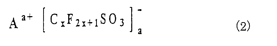
- the electrolyte contains the ionic metal complex represented by the general formula (1) and another component that is at least one compound selected from the above-mentioned fifth to ninth compounds respectively represented by the general formulas A a+ (PF 6 - ) a , A a+ (ClO 4 - ) a , A a+ (BF 4 - ) a , A a+ (AsF 6 - ) a , and A a+ (SbF 6 -p ) a where A a+ is preferably the same ion as that in the general formula (1). If the ionic metal complex is omitted in the second preferred embodiment, the following problem occurs.
- the anion(s) tends to be pyrolyzed at a high temperature of 60°C or higher, thereby generating a Lewis acid(s).
- This Lewis acid decomposes the solvent and makes the electrochemical device inferior in performance and lifetime.
- the omission of the ionic metal complex causes hydrolysis of the anion(s) when the electrolyte is contaminated with a very small amount of water. This hydrolysis generates an acid(s) that makes the electrochemical device inferior in performance and lifetime.
- the above-mentioned pyrolysis and hydrolysis can unexpectedly be prevented by using a mixture of the ionic metal complex and the another component. The reason of this is not clear. It is, however, assumed that the properties of the solution as a whole change somehow to achieve this prevention by a certain interaction between the ionic metal complex and the another component.
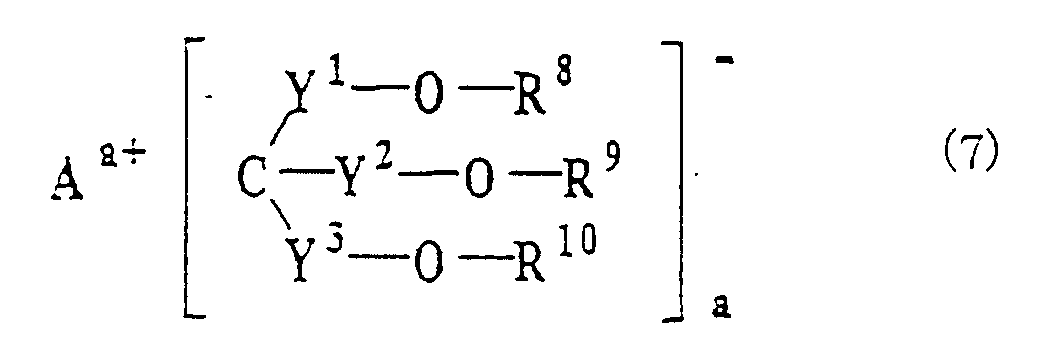
- the electrolyte contains the ionic metal complex represented by the general formula (1) and another component that is at least one compound selected from the above-mentioned tenth to twelfth compounds represented by the general formulas (5), (6) and (7).
- Examples of these compounds are CF 3 CH 2 OSO 3 Li, (CF 3 ) 2 CHOSO 3 Li, (CF 3 CH 2 OSO 2 ) 2 NLi, ((CF 3 ) 2 CHOSO 2 ) 2 NLi, (CF 3 CH 2 OSO 2 )((CF 3 ) 2 CHOSO 2 )NLi, ((CF 3 ) 2 COSO 2 ) 2 NLi, and ((CF 3 ) 2 CHOSO 2 ) 3 CLi.
- Further examples are polymers and oligomers such as [N(Li)SO 2 OCH 2 (CF 2 ) 4 CH 2 OSO 2 ] n where n is a number of 2-1,000. If the ionic metal complex is omitted in the third preferred embodiment, the following problem occurs.
- the another component corrodes the aluminum collector inside the cell when a potential is applied. With this, the capacity is lowered by repeating the charge and discharge cycle.
- the aluminum collector corrosion can unexpectedly be prevented by using a mixture of the ionic metal complex and the another component. The reason of this is not clear. It is, however, assumed that the ionic metal complex is slightly decomposed on the electrode surface and that a film of the ionic metal complex's ligand is formed on the aluminum surface, thereby preventing the aluminum collector corrosion.
- the molar ratio of the ionic metal complex to the at least one compound is preferably 1:99 to 99:1 (or a range from 5:95 to 95:5), more preferably 20:80 to 80:20 (or a range from 30:70 to 70:30), in view of improving the electrochemical device in cycle characteristics and shelf life. If this ratio is less than 1:99 (or 5:95), it may become insufficient to prevent the above-mentioned aluminum corrosion and/or the above-mentioned pyrolysis and hydrolysis, thereby making the electrolyte inferior in cycle characteristics and shelf life. If the ratio is greater than 99:1 (or 95:5), advantages of adding the at least one compound to increase ionic conductivity and electrochemical stability may become insufficient.
- a mixture of electrolyte and non-aqueous solvent or polymer is used as the ion conductor. If a non-aqueous solvent is used, the resulting ion conductor is typically referred to as an electrolytic solution, while if a polymer is used, it is typically referred to as a polymer solid electrolyte. Non-aqueous solvent may also be contained as plasticizer in polymer solid electrolytes.
- non-aqueous solvent is an aprotic solvent that is able to dissolve an electrolyte of the present invention
- examples of this non-aqueous solvent that can be used include carbonates, esters, ethers, lactones, nitriles, amides and sulfones.
- the solvent can either be used alone or in the form of a mixture of two or more types of solvent.
- the solvent include propylene carbonate, ethylene carbonate, diethyl carbonate, dimethyl carbonate, methylethyl carbonate, dimethoxyethane, acetonitrile, propionitrile, tetrahydrofuran, 2-methyltetrahydrofuran, dioxane, nitromethane, N,N-dimethylformamide, dimethylsulfoxide, sulfolane and ⁇ -butyrolactone.
- the non-aqueous solvent of an electrolytic solution is preferably a mixture of a first aprotic solvent having a dielectric constant of 20 or greater and a second aprotic solvent having a dielectric constant of 10 or less.
- lithium salt has a low solubility in the second aprotic solvent (e.g., diethyl ether and dimethyl carbonate). Therefore, it may be difficult to obtain a sufficient ionic conductivity by using only the second aprotic solvent.
- lithium salt has a high solubility in the first aprotic solvent. The resulting solution is, however, high in viscosity.
- the polymer to be mixed with the electrolytes of the invention is an aprotic polymer.
- examples of such polymer include polymers having polyethylene oxide on their main chain or side chain, homopolymers or copolymers of polyvinylidene fluoride, methacrylate polymers and polyacrylonitrile.
- the above-mentioned aprotic non-aqueous solvent can be used.
- the total concentration of the electrolytes of the present invention in these ion conductors is preferably 0.1 mol/dm 3 or more up to the saturated concentration, and more preferably from 0.5 mol/dm 3 to 1.5 mol/dm 3 . If the concentration is lower than 0.1 mol/dm 3 , ion conductivity may become too low.
- the negative electrode material for preparing an electrochemical device there are no particular restrictions on the negative electrode material for preparing an electrochemical device.
- lithium cell lithium metal (metallic lithium) or an alloy of lithium and another metal can be used.
- a lithium ion cell it is possible to use an intercalation compound containing lithium atoms in a matrix of another material, such as carbon, natural graphite or metal oxide. This carbon can be obtained by baking polymer, organic substance, pitch or the like.
- electrical double-layer capacitor it is possible to use activated carbon, porous metal oxide, porous metal, conductive polymer and so forth.
- lithium-containing oxides such as LiCoO 2 , LiNiO 2 , LiMnO 2 and LiMn 2 O 4 ; oxides such as TiO 2 , V 2 O 5 and MoO 3 ; sulfides such as TiS 2 and FeS; and electrically conductive polymers such as polyacetylene, polyparaphenylene, polyaniline or polypyrrole can be used.
- electrical double-layer capacitor activated carbon, porous metal oxide, porous metal, electrically conductive polymer and so forth can be used.
- Examples 1-1 to 1-5 are illustrative of the above-mentioned first preferred embodiment of the invention, and Examples 2-1 to 2-4 are illustrative of the above-mentioned second preferred embodiment of the invention, and Examples 3-1 to 3-4 are illustrative of the above-mentioned third preferred embodiment of the invention.
- a corrosion test of an aluminum collector was performed using the above-mentioned electrolytic solution.
- a beaker type cell was used for the test cell, using aluminum for the working electrode, and lithium metal (metallic lithium) for the counter electrode and reference electrode.
- the working electrode was held at 5 V (Li/Li + ), there was no flow of current whatsoever.
- SEM surface of the working electrode was observed by SEM, there were no changes observed in comparison with that before testing.
- the test cell half cell was prepared in the manner described below.
- the positive electrode was prepared by mixing 5 parts by weight of polyvinylidene fluoride (PVDF) as a binder and 5 parts by weight of acetylene black as a conductor with 90 parts by weight of a LiCoO 2 powder followed by the addition of N,N-dimethylformamide to form a paste. This paste was applied to an aluminum foil and allowed to dry to obtain the test positive electrode. Lithium metal was used for the negative electrode.
- a glass fiber filter as a separator was impregnated with the electrolytic solution, thereby assembling the cell.
- Example 1-1 A corrosion test of an aluminum collector was performed in the same manner as that of Example 1-1. When the working electrode was held at 5 V (Li/Li + ), there was no flow of current whatsoever. Following testing, although the surface of the working electrode was observed by SEM, there were no changes observed in comparison with that before testing.
- the test cell (half cell) was prepared in the same manner as that of Example 1-1, and a constant current charging and discharging test was conducted in the same manner as that of Example 1-1.
- the initial discharge capacity was 115 mAh/g (the positive electrode capacity).
- charging and discharging were repeated 100 times, results were obtained in which the capacity of the 100 th cycle was 86% of the initial capacity.
- Example 1-1 A corrosion test of an aluminum collector was performed in the same manner as that of Example 1-1. When the working electrode was held at 5 V (Li/Li + ), there was no flow of current whatsoever. Following testing, although the surface of the working electrode was observed by SEM, there were no changes observed in comparison with that before testing.
- the test cell (half cell) was prepared in the same manner as that of Example 1-1, and a constant current charging and discharging test was conducted in the same manner as that of Example 1-1.
- the initial discharge capacity was 120 mAh/g (the positive electrode capacity).
- charging and discharging were repeated 100 times, results were obtained in which the capacity of the 100 th cycle was 92% of the initial capacity.
- Example 1-1 A corrosion test of an aluminum collector was performed in the same manner as that of Example 1-1. When the working electrode was held at 5 V (Li/Li + ), there was no flow of current whatsoever. Following testing, although the surface of the working electrode was observed by SEM, there were no changes observed in comparison with that before testing.
- the test cell (half cell) was prepared in the same manner as that of Example 1-1, and a constant current charging and discharging test was conducted in the same manner as that of Example 1-1.
- the initial discharge capacity was 120 mAh/g (the positive electrode capacity).
- charging and discharging were repeated 100 times, results were obtained in which the capacity of the 100 th cycle was 94% of the initial capacity.
- a solution was prepared by adding acetonitrile to 70 parts by weight of a polyethylene oxide (average molecular weight: 10,000). Then, 20 parts by weight of a lithium borate derivative, which is the same as that of Example 1-1, and 10 parts by weight of LiN(SO 2 C 2 F 5 ) 2 were added to the solution. The resulting mixture was cast on a glass, followed by drying to remove the acetonitrile. With this, a polymer solid electrolyte film was prepared.
- the test cell was prepared in the same manner as that of Example 1-1 except in that the polymer solid electrolyte film was used in place of the electrolytic solution and the separator.
- LiCoO 2 was used as a positive electrode material
- lithium metal was used as a negative electrode material.
- a constant current charging and discharging test was conducted at 70°C under the following conditions. The current density was 0.1 mA/cm 2 for both charging and discharging, while charging was performed until 4.2 V and discharging until 3.0 V (vs. LilLi + ). As a result, the initial discharge capacity was 120 mAh/g (the positive electrode capacity). Although charging and discharging were repeated 100 times, results were obtained in which the capacity of the 100 th cycle was 87% of the initial capacity.
- EC ethylene carbonate
- DMC dimethyl carbonate
- Example 1-1 A corrosion test of an aluminum collector was performed in the same manner as that of Example 1-1. When the working electrode was held at 5 V (Li/Li + ), corrosion current was observed. Following testing, the surface of the working electrode was observed by SEM. With this, many pits were observed on its surface. It is assumed that these pits were caused by corrosion.
- the test cell (half cell) was prepared in the same manner as that of Example 1-1, and a constant current charging and discharging test was conducted in the same manner as that of Example 1-1.
- the initial discharge capacity was 117 mAh/g (the positive electrode capacity).
- charging and discharging were repeated 100 times, results were obtained in which the capacity of the 100 th cycle was 69% of the initial capacity.
- Example 1-1 A corrosion test of an aluminum collector was performed in the same manner as that of Example 1-1. When the working electrode was held at 5 V (Li/Li + ), corrosion current was observed. Following testing, the surface of the working electrode was observed by SEM. With this, many pits were observed on its surface. It is assumed that these pits were caused by corrosion.
- the test cell (half cell) was prepared in the same manner as that of Example 1-1, and a constant current charging and discharging test was conducted in the same manner as that of Example 1-1.
- the initial discharge capacity was 112 mAh/g (the positive electrode capacity).
- charging and discharging were repeated 100 times, results were obtained in which the capacity of the 100 th cycle was 67% of the initial capacity.
- EC ethylene carbonate
- DMC dimethyl carbonate
- Example 1-1 A corrosion test of an aluminum collector was performed in the same manner as that of Example 1-1. When the working electrode was held at 5 V (Li/Li + ), corrosion current was observed. Following testing, the surface of the working electrode was observed by SEM. With this, many pits were observed on its surface. It is assumed that these pits were caused by corrosion.
- the test cell (half cell) was prepared in the same manner as that of Example 1-1, and a constant current charging and discharging test was conducted in the same manner as that of Example 1-1.
- the initial discharge capacity was 118 mAh/g (the positive electrode capacity).
- charging and discharging were repeated 100 times, results were obtained in which the capacity of the 100 th cycle was 74% of the initial capacity.
- An electrolytic solution was prepared by the same manner as that of Example 1-1, except that LiN(SO 2 C 2 F 5 ) 2 was replaced with LiPF 6 .
- This electrolytic solution had a lithium borate derivative concentration of 0.05 mol/liter and a LiPF 6 concentration of 0.95 mol/liter.
- a charging and discharging test of an actual cell was conducted using the above-mentioned electrolytic solution.
- the test cell was prepared in the manner described below.
- the positive electrode of LiCoO 2 was prepared by the same manner as that of Example 1-1.
- the negative electrode of natural graphite was prepared by mixing 10 parts by weight of polyvinylidene fluoride (PVDF) as a binder with 90 parts by weight of a LiCoO 2 powder followed by the addition of N,N-dimethylformamide to form a slurry. This slurry was applied to an copper foil and allowed to dry at 150°C for 12 hr to obtain the test negative electrode.
- a polyethylene separator was impregnated with the electrolytic solution, thereby assembling the cell.
- An electrolytic solution was prepared by substantially the same manner as that of Example 1-2, in which LiN(SO 2 CF 3 ) 2 was replaced with LiPF 6 .
- the resulting electrolytic solution had a lithium borate derivative concentration of 0.30 mol/liter and a LiPF 6 concentration of 0.70 mol/liter.
- the test cell was prepared in the same manner as that of Example 2-1, and a constant current charging and discharging test was conducted in the same manner as that of Example 2-1.
- the capacity of the 500 th cycle was 86% of the initial capacity.
- An electrolytic solution was prepared by substantially the same manner as that of Example 1-3, in which LiN(SO 2 CF 3 )(SO 2 C 4 F 9 ) was replaced with LiBF 4 .
- the resulting electrolytic solution had a lithium borate derivative concentration of 0.30 mol/liter and a LiBF 4 concentration of 0.70 mol/liter.
- the test cell was prepared in the same manner as that of Example 2-1, and a constant current charging and discharging test was conducted in the same manner as that of Example 2-1.
- the capacity of the 500 th cycle was 78% of the initial capacity.
- a solution was prepared by adding acetonitrile to 80 parts by weight of a polyethylene oxide-(average molecular weight: 10,000). Then, 10 parts by weight of a lithium borate derivative, which is the same as that of Example 1-1, and 10 parts by weight of LiPF 6 were added to the solution. The resulting mixture was cast on a glass, followed by drying to remove the acetonitrile. With this, a polymer solid electrolyte film was prepared.
- the test cell was prepared in the same manner as that of Example 2-1 except in that the polymer solid electrolyte film was used in place of the electrolytic solution and the separator.
- LiCoO 2 was used as a positive electrode material
- natural graphite was used as a negative electrode material.
- a constant current charging and discharging test was conducted at 70°C under the following conditions. The current density was 0.1 mA/cm 2 for both charging and discharging, while charging was performed until 4.2 V and discharging until 3.0 V (vs. Li/Li + ). As a result, the initial discharge capacity was 120 mAh/g (the positive electrode capacity). Although charging and discharging were repeated 500 times, results were obtained in which the capacity of the 500 th cycle was 91% of the initial capacity.
- EC ethylene carbonate
- DMC dimethyl carbonate
- the test cell was prepared in the same manner as that of Example 2-1, and a constant current charging and discharging test was conducted in the same manner as that of Example 2-1.
- the capacity of the 500 th cycle was 64% of the initial capacity.
- EC ethylene carbonate
- DMC dimethyl carbonate
- the test cell was prepared in the same manner as that of Example 2-1, and a constant current charging and discharging test was conducted in the same manner as that of Example 2-1.
- the capacity of the 500 th cycle was 46% of the initial capacity.
- EC ethylene carbonate
- DMC dimethyl carbonate
- Example 1-1 A corrosion test of an aluminum collector was performed in the same manner as that of Example 1-1. When the working electrode was held at 5 V (Li/Li + ), there was no flow of current whatsoever. Following testing, although the surface of the working electrode was observed by SEM, there were no changes observed in comparison with that before testing.
- the test cell was prepared by the same manner as that of Example 2-1.
- a constant current charging and discharging test was conducted by the same manner as that of Example 2-1, except that the test was conducted at an environmental temperature of 25°C.
- the capacity of the 500 th cycle was 91% of the initial capacity.
- EC ethylene carbonate
- DEC diethyl carbonate
- Example 1-1 A corrosion test of an aluminum collector was performed in the same manner as that of Example 1-1. When the working electrode was held at 5 V (Li/Li + ), there was no flow of current whatsoever. Following testing, although the surface of the working electrode was observed by SEM, there were no changes observed in comparison with that before testing.
- the test cell was prepared by the same manner as that of Example 2-1.
- a constant current charging and discharging test was conducted by the same manner as that of Example 2-1, except that the test was conducted at an environmental temperature of 60°C.
- the capacity of the 500 th cycle was 85% of the initial capacity.
- EC ethylene carbonate
- EMC ethylmethyl carbonate
- Example 1-1 A corrosion test of an aluminum collector was performed in the same manner as that of Example 1-1. When the working electrode was held at 5 V (Li/Li + ), there was no flow of current whatsoever. Following testing, although the surface of the working electrode was observed by SEM, there were no changes observed in comparison with that before testing.
- the test cell was prepared by the same manner as that of Example 2-1.
- a constant current charging and discharging test was conducted by the same manner as that of Example 2-1, except that the test was conducted at an environmental temperature of 60°C.
- the capacity of the 500 th cycle was 88% of the initial capacity.
- a solution was prepared by adding acetonitrile to 70 parts by weight of a polyethylene oxide (average molecular weight: 10,000). Then, 5 parts by weight of a lithium borate derivative, which was the same as that of Example 1-1, and 25 parts by weight of ((CF 3 ) 2 CHOSO 2 ) 2 NLi were added to the solution. The resulting mixture was cast on a glass, followed by drying to remove the acetonitrile. With this, a polymer solid electrolyte film was prepared.
- a corrosion test of an aluminum collector was performed using a laminate including the solid electrolyte film interposed between an aluminum electrode (working electrode) and a lithium electrode. This laminate was prepared by press welding. When the working electrode was held at 5 V (Li/Li + ), there was no flow of current whatsoever. Following testing, although the surface of the working electrode was observed by SEM, there were no changes observed in comparison with that before testing.
- the test cell was prepared in the same manner as that of Example 2-4, and a constant current charging and discharging test was conducted in the same manner as that of Example 2-4 except that charging and discharging were repeated 100 times.
- the initial discharge capacity was 120 mAh/g (the positive electrode capacity).
- the capacity of the 100 th cycle was 94% of the initial capacity.
- EC ethylene carbonate
- DMC dimethyl carbonate
- Example 1-1 A corrosion test of an aluminum collector was performed in the same manner as that of Example 1-1. When the working electrode was held at 5 V (Li/Li + ), corrosion current was observed. Following testing, the surface of the working electrode was observed by SEM. With this, many pits were observed on its surface. It is assumed that these pits were caused by corrosion.
- the test cell was prepared in the same manner as that of Example 2-1, and a constant current charging and discharging test was conducted in the same manner as that of Example 2-1, except that the test was conducted at an environmental temperature of 25°C.
- the capacity of the 500 th cycle was 62% of the initial capacity.
- Example 1-1 A corrosion test of an aluminum collector was performed in the same manner as that of Example 1-1. When the working electrode was held at 5 V (Li/Li + ), corrosion current was observed. Following testing, the surface of the working electrode was observed by SEM. With this, many pits were observed on its surface. It is assumed that these pits were caused by corrosion.
- the test cell was prepared in the same manner as that of Example 2-1, and a constant current charging and discharging test was conducted in the same manner as that of Example 2-1, except that the test was conducted at an environmental temperature of 60°C.
- the capacity of the 500 th cycle was 58% of the initial capacity.
- EC ethylene carbonate
- EMC ethylmethyl carbonate
- the test cell was prepared in the same manner as that of Example 2-1, and a constant current charging and discharging test was conducted in the same manner as that of Example 2-1, except that the test was conducted at an environmental temperature of 60°C.
- the capacity of the 500 th cycle was 25% of the initial capacity.
Landscapes
- Chemical & Material Sciences (AREA)
- Engineering & Computer Science (AREA)
- Chemical Kinetics & Catalysis (AREA)
- Electrochemistry (AREA)
- Power Engineering (AREA)
- Manufacturing & Machinery (AREA)
- General Chemical & Material Sciences (AREA)
- Microelectronics & Electronic Packaging (AREA)
- Physics & Mathematics (AREA)
- Inorganic Chemistry (AREA)
- General Physics & Mathematics (AREA)
- Condensed Matter Physics & Semiconductors (AREA)
- Materials Engineering (AREA)
- Secondary Cells (AREA)
- Electric Double-Layer Capacitors Or The Like (AREA)
Abstract
Description


Claims (21)
- An electrolyte for an electrochemical device, said electrolyte comprising:a first compound that is an ionic metal complex represented by the general formula (1); andat least one compound selected from the group consisting of second to fourth compounds respectively represented by the general formulas (2) to (4), fifth to ninth compounds respectively represented by the general formulas Aa+(PF6- )a, Aa+(ClO4- )a, Aa+(BF4- )a, Aa+(AsF6- )a, and Aa+(SbF6- )a, and tenth to twelfth compounds respectively represented by the general formulas (5) to (7),


 wherein M is a transition metal selected from the group consisting of elements of groups 3-11 of the periodic table, or an element selected from the group consisting of elements of groups 12-15 of the periodic table;Aa+ represents a metal ion, onium ion or hydrogen ion;a represents a number from 1 to 3; b represents a number from 1 to 3; p is b/a; m represents a number from 1 to 4; n represents a number from 0 to 8; q is 0 or 1;X1 represents O, S, NR5 or NR5R6;each of R1 and R2 independently represents H, a halogen, a C1-C10 alkyl group or C1-C10 halogenated alkyl group;R3 represents a C1-C10 alkylene group, C1-C10 halogenated alkylene group, C4-C20 arylene group or C4-C20 halogenated arylene group, these alkylene and arylene groups of said R3 optionally having substituents and hetero atoms, one of said R3 being optionally bonded with another of said R3;R4 represents a halogen, C1-C10 alkyl group, C1-C10 halogenated alkyl group, C4-C20 aryl group, C4-C20 halogenated aryl group or X2R7, these alkyl and aryl groups of said R4 optionally having substituents and hetero atoms, one of said R4 being optionally bonded with another of said R4;X2 represents O, S, NR5 or NR5R6;each of R5 and R6 represents H or a C1-C10 alkyl group;R7 represents a C1-C10 alkyl group, C1-C10 halogenated alkyl group, C4-C20 aryl group or C4-C20 halogenated aryl group;each of x, y and z independently represents a number from 1 to 8each of Y1, Y2 and Y3 independently represents a SO2 group or CO group; andeach of R8, R9 and R10 independently represents an electron-attractive organic substituent optionally having a substituent or a hetero atom, at least two of said R8, R9 and R10 being optionally bonded together to form a ring, at least one of said R8, R9 and R10 being optionally bonded with an adjacent molecule to form a polymer.
 - An electrolyte according to claim 1, wherein said at least compound is selected from the group consisting of said second to fourth compounds,said m represents a number from 1 to 3,said n represents a number from 0 to 4,said R3 represents a C1-C10 alkylene group, C1-C10 halogenated alkylene group, C4-C20 arylene group or C4-C20 halogenated arylene group, andsaid R4 represents a halogen, C1-C10 alkyl group, C1-C10 halogenated alkyl group, C4-C20 aryl group, C4-C20 halogenated aryl group or said X2R7.
- An electrolyte according to claim 1, wherein said at least one compound is selected from the group consisting of said fifth to ninth compounds,said m represents a number from 1 to 3,said n represents a number from 0 to 4,said R3 represents a C1-C10 alkylene group, C1-C10 halogenated alkylene group, C4-C20 arylene group or C4-C20 halogenated arylene group, andsaid R4 represents a halogen, C1-C10 alkyl group, C1-C10 halogenated alkyl group, C4-C20 aryl group, C4-C20 halogenated aryl group or said X2R7.
- An electrolyte according to claim 1, wherein said M is an element selected from the group consisting of Al, B, V, Ti, Si, Zr, Ge, Sn, Cu, Y, Zn, Ga, Nb, Ta, Bi, P, As, Sc, Hf, and Sb.
- An electrolyte according to claim 4, wherein said M is an element selected from the group consisting of Al, B and P.
- An electrolyte according to claim 1, wherein said Aa+ is a lithium ion, quaternary ammonium ion or hydrogen ion.
- An electrolyte according to claim 1, wherein at least one of said R1 and said R2 is a fluorinated alkyl group.
- An electrolyte according to claim 7, wherein said fluorinated alkyl group is trifluoromethyl group.
- An electrolyte according to claim 1, wherein said R3 is such that a chelate ring containing said M in the general formula (1) is a closed loop of bonded atoms of 5-10 in number.
- An electrolyte according to claim 1, wherein said R7 is a C1-C10 fluorinated alkyl group.
- An electrolyte according to claim 1, wherein a molar ratio of said first compound to said at least one compound is 1:99 to 99:1.
- An ion conductor for an electrochemical device, said ion conductor comprising:an electrolyte according to claim 1; anda member selected from the group consisting of a nonaqueous solvent, a polymer and a mixture thereof, said member dissolving therein said electrolyte.
- An ion conductor according to claim 12, wherein said nonaqueous solvent is an aprotic solvent, and thereby said ion conductor is an electrolytic solution.
- An ion conductor according to claim 13, wherein said nonaqueous solvent is a mixture of a first aprotic solvent having a dielectric constant of 20 or greater and a second aprotic solvent having a dielectric constant of 10 or less.
- An ion conductor according to claim 12, wherein said Aa+ is a lithium ion.
- An ion conductor according to claim 12, wherein said polymer is an aprotic polymer, and thereby said ion conductor is a solid electrolyte.
- An ion conductor according to claim 12, which has a concentration of said electrolyte within a range of from 0.1 mol/dm3 to a saturated concentration.
- An ion conductor according to claim 17, wherein said concentration is within a range of from 0.5 mol/dm3 to 1.5 mol/dm3.
- An electrochemical device comprising:(a) first and second electrodes; and(b) an ion conductor receiving therein said first and second electrodes, said ion conductor comprising:(1) an electrolyte according to claim 1; and(2) a member selected from the group consisting of a nonaqueous solvent, a polymer and a mixture thereof, said member dissolving therein said electrolyte.
- An electrochemical device according to claim 19, which is a cell or an electrical double-layer capacitor.
- An electrochemical device according to claim 20, wherein said cell is a lithium cell or a lithium ion cell.
Applications Claiming Priority (10)
| Application Number | Priority Date | Filing Date | Title |
|---|---|---|---|
| JP2000134926 | 2000-05-08 | ||
| JP2000134926 | 2000-05-08 | ||
| JP2000173094 | 2000-06-09 | ||
| JP2000173094 | 2000-06-09 | ||
| JP2001020898A JP4076726B2 (en) | 2000-05-08 | 2001-01-30 | Lithium battery and electrolyte for lithium ion battery, electrolyte solution or solid electrolyte thereof, and lithium battery or lithium ion battery |
| JP2001020898 | 2001-01-30 | ||
| JP2001020899A JP4076727B2 (en) | 2000-06-09 | 2001-01-30 | Lithium battery and electrolyte for lithium ion battery, electrolyte solution or solid electrolyte thereof, and lithium battery or lithium ion battery |
| JP2001020899 | 2001-01-30 | ||
| JP2001117170 | 2001-04-16 | ||
| JP2001117170A JP4076735B2 (en) | 2001-04-16 | 2001-04-16 | Lithium battery and electrolyte for lithium ion battery, electrolyte solution or solid electrolyte thereof, and lithium battery or lithium ion battery |
Publications (2)
| Publication Number | Publication Date |
|---|---|
| EP1154450A2 true EP1154450A2 (en) | 2001-11-14 |
| EP1154450A3 EP1154450A3 (en) | 2005-10-05 |
Family
ID=27531522
Family Applications (1)
| Application Number | Title | Priority Date | Filing Date |
|---|---|---|---|
| EP01110673A Withdrawn EP1154450A3 (en) | 2000-05-08 | 2001-05-02 | Electrolyte for electrochemical device |
Country Status (3)
| Country | Link |
|---|---|
| US (1) | US6461773B1 (en) |
| EP (1) | EP1154450A3 (en) |
| CN (1) | CN1182617C (en) |
Cited By (2)
| Publication number | Priority date | Publication date | Assignee | Title |
|---|---|---|---|---|
| WO2003017409A3 (en) * | 2001-08-17 | 2004-01-22 | Merck Patent Gmbh | Polymer electrolyte and the use thereof in galvanic cells |
| WO2010097678A1 (en) * | 2009-02-24 | 2010-09-02 | Toyota Jidosha Kabushiki Kaisha | Lithium-ion secondary battery and manufacture method therefor |
Families Citing this family (13)
| Publication number | Priority date | Publication date | Assignee | Title |
|---|---|---|---|---|
| TWI263235B (en) | 2002-04-02 | 2006-10-01 | Nippon Catalytic Chem Ind | Material for electrolytic solutions and use thereof |
| WO2006077380A2 (en) * | 2005-01-18 | 2006-07-27 | Oxis Energy Limited | Improvements relating to electrolyte compositions for batteries using sulphur or sulphur compounds |
| CN101395748B (en) * | 2006-03-08 | 2012-05-02 | Cap-Xx有限公司 | Electrolyte |
| US7820323B1 (en) | 2006-09-07 | 2010-10-26 | The United States Of America As Represented By The Secretary Of The Army | Metal borate synthesis process |
| EP2629352A1 (en) | 2012-02-17 | 2013-08-21 | Oxis Energy Limited | Reinforced metal foil electrode |
| ES2671399T3 (en) | 2013-03-25 | 2018-06-06 | Oxis Energy Limited | A method to charge a lithium-sulfur cell |
| EP2784850A1 (en) | 2013-03-25 | 2014-10-01 | Oxis Energy Limited | A method of cycling a lithium-sulphur cell |
| EP2784851B1 (en) | 2013-03-25 | 2015-08-19 | Oxis Energy Limited | A method of charging a lithium-sulphur cell |
| GB2517228B (en) | 2013-08-15 | 2016-03-02 | Oxis Energy Ltd | Laminate cell |
| KR20160100958A (en) | 2013-12-17 | 2016-08-24 | 옥시스 에너지 리미티드 | Electrolyte for a lithium-sulphur cell |
| US10811728B2 (en) | 2014-05-30 | 2020-10-20 | Oxis Energy Ltd. | Lithium-sulphur cell |
| CN105789696B (en) * | 2016-04-22 | 2018-05-04 | 中山大学 | A kind of electrolyte containing new lithium borate and the battery using the lithium salts |
| CN116454368A (en) * | 2022-01-05 | 2023-07-18 | 万华化学集团股份有限公司 | Diaphragm-free lithium ion battery |
Family Cites Families (7)
| Publication number | Priority date | Publication date | Assignee | Title |
|---|---|---|---|---|
| US3539614A (en) * | 1966-02-07 | 1970-11-10 | Sprague Electric Co | Quaternary ammonium diorganoboron compounds |
| GB2143228A (en) * | 1983-07-13 | 1985-02-06 | Standard Telephones Cables Ltd | Electrolytes |
| DE4316104A1 (en) * | 1993-05-13 | 1994-11-17 | Manfred Wuehr | Electrolyte for use in a galvanic cell |
| JP2000173343A (en) * | 1998-12-02 | 2000-06-23 | Japan Carlit Co Ltd:The | Ion conductive polymer electrolyte |
| DE19910968A1 (en) * | 1999-03-12 | 2000-11-09 | Merck Patent Gmbh | Use of additives in electrolytes for electrochemical cells |
| JP3498905B2 (en) * | 1999-08-02 | 2004-02-23 | セントラル硝子株式会社 | Electrolyte for electrochemical devices |
| JP3824465B2 (en) | 1999-08-02 | 2006-09-20 | セントラル硝子株式会社 | Synthesis of ionic complexes |
-
2001
- 2001-04-30 CN CNB011228083A patent/CN1182617C/en not_active Expired - Fee Related
- 2001-05-02 EP EP01110673A patent/EP1154450A3/en not_active Withdrawn
- 2001-05-08 US US09/850,191 patent/US6461773B1/en not_active Expired - Lifetime
Cited By (2)
| Publication number | Priority date | Publication date | Assignee | Title |
|---|---|---|---|---|
| WO2003017409A3 (en) * | 2001-08-17 | 2004-01-22 | Merck Patent Gmbh | Polymer electrolyte and the use thereof in galvanic cells |
| WO2010097678A1 (en) * | 2009-02-24 | 2010-09-02 | Toyota Jidosha Kabushiki Kaisha | Lithium-ion secondary battery and manufacture method therefor |
Also Published As
| Publication number | Publication date |
|---|---|
| EP1154450A3 (en) | 2005-10-05 |
| US20020022181A1 (en) | 2002-02-21 |
| US6461773B1 (en) | 2002-10-08 |
| CN1324124A (en) | 2001-11-28 |
| CN1182617C (en) | 2004-12-29 |
Similar Documents
| Publication | Publication Date | Title |
|---|---|---|
| US6787267B2 (en) | Electrolyte for electrochemical device | |
| US6783896B2 (en) | Electrolyte for electrochemical device | |
| US6485868B1 (en) | Electrolyte for electrochemical device | |
| JP5544748B2 (en) | Electrolytes for electrochemical devices, electrolytes using the same, and nonaqueous electrolyte batteries | |
| JP3722685B2 (en) | Electrolyte for electrochemical device and battery using the same | |
| JP3463926B2 (en) | Electrolyte for electrochemical devices | |
| KR20160136686A (en) | Lithium metal battery | |
| US6461773B1 (en) | Electrolyte for electrochemical device | |
| JP3730861B2 (en) | Electrolytes for electrochemical devices, electrolytes or solid electrolytes thereof, and batteries | |
| JP3730860B2 (en) | Electrolytes for electrochemical devices, electrolytes or solid electrolytes thereof, and batteries | |
| JP2002260734A (en) | Electrolyte for electrochemical device, its electrolyte solution or solid electrolyte and battery | |
| JP4076738B2 (en) | Lithium battery and electrolyte for lithium ion battery, electrolyte solution or solid electrolyte thereof, and lithium battery or lithium ion battery | |
| JP4190207B2 (en) | Electrolytes for electrochemical devices, electrolytes or solid electrolytes thereof, and batteries | |
| JP2004146071A (en) | Electrolyte for electrochemical device, its electrolyte solution or solid electrolyte and battery | |
| JP3730856B2 (en) | Electrolytes for electrochemical devices, electrolytes or solid electrolytes thereof, and batteries | |
| JP2002260733A (en) | Electrolyte for electrochemical device, its electrolyte solution or solid electrolyte and battery | |
| JP4190206B2 (en) | Electrolytes for electrochemical devices, electrolytes or solid electrolytes thereof, and batteries | |
| JP4175798B2 (en) | Electrolytes for electrochemical devices, electrolytes or solid electrolytes thereof, and batteries | |
| JP2002260732A (en) | Electrolyte for electrochemical device, its electrolyte solution or solid electrolyte and battery | |
| JP4076735B2 (en) | Lithium battery and electrolyte for lithium ion battery, electrolyte solution or solid electrolyte thereof, and lithium battery or lithium ion battery | |
| JP2002260727A (en) | Electrolyte for electrochemical device, its electrolyte solution or solid electrolyte and battery | |
| JP2002063935A (en) | Electrolyte for electrochemical device, its electrolytic solution or solid electrolyte and battery | |
| JP2002252029A (en) | Electrolyte for electrochemistry device, its electrolytic solution or solid electrolyte and battery | |
| JP2002260731A (en) | Electrolyte for electrochemical device, its electrolyte solution or solid electrolyte and battery | |
| JP2002033126A (en) | Electrolyte for electrochemical device, electrolytic solution or solid electrolyte and battery |
Legal Events
| Date | Code | Title | Description |
|---|---|---|---|
| PUAI | Public reference made under article 153(3) epc to a published international application that has entered the european phase |
Free format text: ORIGINAL CODE: 0009012 |
|
| AK | Designated contracting states |
Kind code of ref document: A2 Designated state(s): AT BE CH CY DE DK ES FI FR GB GR IE IT LI LU MC NL PT SE TR |
|
| AX | Request for extension of the european patent |
Free format text: AL;LT;LV;MK;RO;SI |
|
| PUAL | Search report despatched |
Free format text: ORIGINAL CODE: 0009013 |
|
| AK | Designated contracting states |
Kind code of ref document: A3 Designated state(s): AT BE CH CY DE DK ES FI FR GB GR IE IT LI LU MC NL PT SE TR |
|
| AX | Request for extension of the european patent |
Extension state: AL LT LV MK RO SI |
|
| 17P | Request for examination filed |
Effective date: 20060202 |
|
| AKX | Designation fees paid |
Designated state(s): DE FR GB |
|
| 17Q | First examination report despatched |
Effective date: 20070118 |
|
| STAA | Information on the status of an ep patent application or granted ep patent |
Free format text: STATUS: THE APPLICATION IS DEEMED TO BE WITHDRAWN |
|
| 18D | Application deemed to be withdrawn |
Effective date: 20081223 |