EP1154337A2 - Ceramic heater for toner-fixing units and method for manufacturing the heater - Google Patents
Ceramic heater for toner-fixing units and method for manufacturing the heater Download PDFInfo
- Publication number
- EP1154337A2 EP1154337A2 EP01304105A EP01304105A EP1154337A2 EP 1154337 A2 EP1154337 A2 EP 1154337A2 EP 01304105 A EP01304105 A EP 01304105A EP 01304105 A EP01304105 A EP 01304105A EP 1154337 A2 EP1154337 A2 EP 1154337A2
- Authority
- EP
- European Patent Office
- Prior art keywords
- heat
- ceramic
- ceramic heater
- resistant film
- resistant
- Prior art date
- Legal status (The legal status is an assumption and is not a legal conclusion. Google has not performed a legal analysis and makes no representation as to the accuracy of the status listed.)
- Granted
Links
Images



Classifications
-
- G—PHYSICS
- G03—PHOTOGRAPHY; CINEMATOGRAPHY; ANALOGOUS TECHNIQUES USING WAVES OTHER THAN OPTICAL WAVES; ELECTROGRAPHY; HOLOGRAPHY
- G03G—ELECTROGRAPHY; ELECTROPHOTOGRAPHY; MAGNETOGRAPHY
- G03G15/00—Apparatus for electrographic processes using a charge pattern
- G03G15/20—Apparatus for electrographic processes using a charge pattern for fixing, e.g. by using heat
- G03G15/2003—Apparatus for electrographic processes using a charge pattern for fixing, e.g. by using heat using heat
- G03G15/2014—Apparatus for electrographic processes using a charge pattern for fixing, e.g. by using heat using heat using contact heat
- G03G15/2053—Structural details of heat elements, e.g. structure of roller or belt, eddy current, induction heating
-
- G—PHYSICS
- G03—PHOTOGRAPHY; CINEMATOGRAPHY; ANALOGOUS TECHNIQUES USING WAVES OTHER THAN OPTICAL WAVES; ELECTROGRAPHY; HOLOGRAPHY
- G03G—ELECTROGRAPHY; ELECTROPHOTOGRAPHY; MAGNETOGRAPHY
- G03G15/00—Apparatus for electrographic processes using a charge pattern
- G03G15/20—Apparatus for electrographic processes using a charge pattern for fixing, e.g. by using heat
- G03G15/2003—Apparatus for electrographic processes using a charge pattern for fixing, e.g. by using heat using heat
- G03G15/2014—Apparatus for electrographic processes using a charge pattern for fixing, e.g. by using heat using heat using contact heat
- G03G15/2064—Apparatus for electrographic processes using a charge pattern for fixing, e.g. by using heat using heat using contact heat combined with pressure
-
- H—ELECTRICITY
- H05—ELECTRIC TECHNIQUES NOT OTHERWISE PROVIDED FOR
- H05B—ELECTRIC HEATING; ELECTRIC LIGHT SOURCES NOT OTHERWISE PROVIDED FOR; CIRCUIT ARRANGEMENTS FOR ELECTRIC LIGHT SOURCES, IN GENERAL
- H05B3/00—Ohmic-resistance heating
- H05B3/0095—Heating devices in the form of rollers
Definitions
- the present invention relates to a heating-type toner-fixing unit in which (a) a pressure roller drives a continuous heat-resistant film by pressing it against a ceramic heater positioned on a heating cylinder and (b) a toner image is fixed on a copying sheet fed between the pressure roller and the heat-resistant film.
- the present invention particularly relates to a ceramic heater for a toner-fixing unit in which the ceramic heater is positioned on a heating cylinder.
- Toner-fixing units used in fax machines, copiers, printers, and other image-forming machines transfer a toner image formed on a photosensitive drum onto a sheet of paper or another copying sheet before fixing it on the surface of the sheet by concurrent heating and pressing.
- These toner-fixing units comprise a heating roller and a plastic pressure roller.
- One of these units for example, uses a cylindrical metal roller provided with a halogen lamp or another heat source as the heating roller so that the surface region of the metal roller is heated by the heat source to fix the toner.
- toner-fixing system In addition to this fixing system, another toner-fixing system has been offered and used in recent years which uses a ceramic heater (hereinafter also simply called “a heater”) without using a heating roller.
- a ceramic heater hereinafter also simply called "a heater”
- the latter system has been disclosed in published Japanese patent applications Tokukaihei 1-263679, Tokukaihei 2-157878, and Tokukaishou 63-313182, for example.
- these disclosed systems (a) mount a ceramic heater on a plastic support, (b) use a pressure roller to press a heat-resistant film against the ceramic heater so that the heat-resistant film can move at the same speed as the peripheral speed of the pressure roller to feed a sheet of paper, and (c) fix a toner image on the surface of the sheet.
- the heat-resistant film is composed of a material comprising heat-resistant plastic, metal, or both.
- the latter fixing system using a toner-fixing unit comprising a ceramic heater and a heat-resistant film, has a heater significantly smaller in thermal capacity than that of the former system, using a metal roller. Therefore, the latter system can reduce the power consumption and eliminate the preheating of the heater after the power is supplied, so it is advantageous in having an excellent quick-start property.
- FIG. 1 schematically shows a modified latter fixing system in which a continuous heat-resistant film revolves around a heating cylinder.
- a ceramic heater 1 is positioned on a heating cylinder 2.
- a continuous heat-resistant film 3 revolves on the periphery of the heating cylinder 2.
- a pressure roller 4 has a rubber layer or another elastic layer formed on its periphery and its rotation revolves the heat-resistant film 3 at the same speed as its peripheral speed.
- the heating cylinder 2 and the pressure roller 4 are pressed against each other by springs (not shown in Fig. 1) provided at the fixed portions of both of their ends. This pressure deforms the elastic layer on the periphery of the pressure roller 4, forming a nip portion 5 having a width of W .
- a toner image 6a is formed on a copying sheet 6 such as a sheet of paper.
- the copying sheet 6 is fed between the heat-resistant film 3 and the pressure roller 4 each rotating in the direction of the arrow.
- the toner image 6a on the copying sheet 6 is heated and pressed at the nip portion 5 to be fixed as an image 6b.
- the ceramic heater 1 attached to the heating cylinder 2 has a structure shown schematically in Fig. 2, for example.
- Figure 2 is a plan view viewed from the downside.
- a ceramic base material 11 supports (a) one or more heating elements 12 provided at the face (the fixing face) where the ceramic heater 1 is positioned opposite to the pressure roller 4 via the heat-resistant film 3 and (b) current-feeding electrodes 13 for supplying electric power to the heating elements 12.
- the ceramic base material 11 generally has a shape of a thin rectangular flat plate as a whole.
- the heating elements 12 are formed at the fixing-face side of the ceramic heater 1, and an overcoat glass layer is formed on the heating elements as a protective layer. The glass layer not only ensures electrical insulation but also protects the heating elements 12 and other members against the sliding contact with the heat-resistant film 3.
- Alumina is generally used now as the ceramic base material 11 of the foregoing ceramic heater 1.
- the ceramic heaters using alumina base materials in this image-fixing system have a fixing rate of 6 to 16 ppm.
- the unit "ppm” is the abbreviation of "papers per minute” and signifies the number of sheets of paper in A4 size (210 X 297 mm) fed in a minute.
- the foregoing fixing rate however, no longer satisfies the market's requirement. The market now requires to increase the rate to 24 ppm or more.
- a voltage of 100 or 200 V is applied to the heating elements to produce a Joule heat of hundreds of watts or more. This heat raises the temperature to about 200 °C in 2 to 6 seconds.
- ceramic heaters using alumina base materials pose a problem of fracture caused by heat shock.
- the fixing rate is increased, the time for transferring the heat from the heater to a sheet of paper (a copying sheet) is shortened. This requires the increase in the amount of heat to be supplied from the heater to the copying sheet per unit time, because the toner fixing requires a certain amount of heat. As a result, the increase in the fixing rate tends to increase the heat shock applied to the heater, increasing the percentage of heater fracture.
- Tokukaihei 9-80940 improves the temperature responsivity of the heater by exploiting the fact that aluminum nitride has a higher thermal conductivity than alumina.
- Tokukaihei 9-197861 intends to improve the fixing quality, to increase the possibility of high-speed printing, and to reduce the power consumption by utilizing the highly heat-conductive quality of aluminum nitride.
- the use of aluminum nitride as the base material of the ceramic heater can solve the problem of heater fracture.
- further increase in the fixing rate poses another problem of a reduction in the durability of the heat-resistant film (hereinafter also simply called "film”) revolving around the heating cylinder provided with the ceramic heater.
- the conventional ceramic heater has a shape of a rectangular flat plate as a whole. Consequently, the continuous heat-resistant film, which is tubular when viewed from the side, is pressed against the flat fixing face provided on the heating cylinder by the pressure roller and deformed to a flat shape at this position, the nip portion.
- This deformation accompanied by the high-speed revolution applies a heavy load to the film and may cause the film to fracture at an early stage. In particular, a fixing rate exceeding 24 ppm increases this tendency.
- This problem has been an obstacle for increasing the fixing rate in a system using a heat-resistant film and a ceramic heater.
- an object of the present invention is to offer an improved ceramic heater for a fixing system using a heat-resistant film and a ceramic heater.
- the ceramic heater is characterized by the following features:
- the ceramic heater offered by the present invention is used for a toner-fixing unit, which comprises:
- the toner-fixing unit feeds a copying sheet to the nip portion by the revolution of the heat-resistant film and the pressure roller and fixes a toner image on the copying sheet by the pressure of the pressure roller, and the heat from the ceramic heater on the heating cylinder.
- the ceramic heater of the present invention comprises a ceramic base material, a heating element, and current-feeding electrodes.
- the heating element and current-feeding electrodes are made of heat-resistant metal or heat-resistant alloy and formed on the ceramic base material.
- the ceramic base material at least one part of the face that contacts the heat-resistant film is curved when viewed from a direction perpendicular to the feeding direction of the copying sheet.
- the method for manufacturing the ceramic heater of the present invention is a method for manufacturing the ceramic heater to be used in the foregoing toner-fixing unit.
- a ceramic base material is extrusion-formed in such a manner that at least one part of the face that contacts the heat-resistant film is curved when viewed from a direction perpendicular to the feeding direction of the copying sheet.
- a heating element or current-feeding electrodes are printed with heat-resistant metal pastes or heat-resistant alloy pastes on the formed body at the face where the formed body contacts the heat-resistant film or at the reverse side of the face, and the formed body with the heating element and the current feeding electrodes is sintered.
- the present invention reduces the degree of deformation of the heat-resistant film to lighten the load applied to the film at the time of revolution, so that the fracture of the film can be prevented.
- the heat-resistant film can be used at a fixing rate exceeding 24 ppm, which cannot be realized by the prior art. Consequently, the present invention enables the realization of a fixing system that uses a ceramic heater and a heat-resistant film, that consumes fixing power as low as the conventional system, and that can fix images at a high rate exceeding 24 ppm.
- the fixing face In the ceramic heater of the present invention attached to a heating cylinder, at least one part of the face (hereinafter also called the fixing face) that contacts the heat-resistant film is curved when viewed from a direction perpendicular to the feeding direction of the copying sheet.
- a curved portion in the fixing face of the ceramic heater can reduce the sliding load of the heat-resistant film.
- the degree of the deformation of the heat-resistant film can be reduced. As a result, the durability of the heat-resistant film can be improved.
- a specific curved shape of a fixing face it is desirable that all the adjoining curves be connected smoothly with one another at a cross section when viewed from a direction perpendicular to the feeding direction of the copying sheet.
- the whole of the fixing face of a ceramic heater form a circular arc.
- the whole of the outside surface of a ceramic base material to be used as the fixing face of a ceramic heater have a curved shape having much the same radius of curvature as that of the heat-resistant film. This condition can minimize the degree of deformation of the heat-resistant film, thus preventing most of the fracture of the heat-resistant film.
- the fixing face of the ceramic heater has a radius of curvature larger than that of the heat-resistant film, the nip portion increases its width, improving the fixing quality.
- this condition tends to shorten the lifetime of the film, depending on the feeding speed. Therefore, notwithstanding that the fixing face of the ceramic heater may have a radius of curvature slightly larger than that of the heat-resistant film, it is necessary to obtain a proper combination of the radius of curvature and the feeding speed of the copying sheet.
- the ceramic heater In order to increase the contact area between the pressure roller, the heat-resistant film, and the ceramic heater, the fixing face of the ceramic heater can have a circular arc in the opposite direction to that of the heating cylinder.
- the circular arc can also have a radius of curvature the same as or larger than that of the opposite pressure roller.
- the ceramic heater can have a flat shape at the nip portion in order to secure the specified nip width and curved shapes at portions other than the nip portion in the fixing face.
- the ceramic base material of a ceramic heater has a sufficient thickness to endure the cycles of pressure and heat in operation at both ends in the foregoing cross section and has an average thickness nearly the same as that of the conventional heater in the cross section, the ceramic heater can have nearly the same thermal capacity as that of the conventional heater. This condition can improve the durability of the heat-resistant film without adversely affecting the properties such as power consumption and start-up time.
- a heating element 12 can be formed either at the fixing-face side or at the back-face side of a ceramic base material 11 (the reverse side of the fixing face, shall hereinafter be referred to as "the back face" in the present invention).
- the ceramic base material for a ceramic heater be a ceramic consisting mainly of aluminum nitride or silicon nitride, both of which are highly heat conductive.
- An aluminum nitride-based ceramic has higher thermal conductivity than alumina and high-resistance to heat shock. Consequently, even when a rapid temperature rise in a heating element at the time of fixing applies a large thermal shock to a ceramic heater, the heater can be immune to fracture.
- a silicon nitride-based ceramic has extremely high mechanical strength. Therefore, a heater made of this ceramic material has minimal fracture by heat shock.
- an alumina-based ceramic heater can be used provided that the heater has the curved shape specified by the present invention.
- a heat-resistant film, which moves in contact with a ceramic heater, can be composed of heat-resistant plastic, metal, or a combination of these as with the conventional heat-resistant film.
- a method for manufacturing the ceramic heater of the present invention, having a curved fixing face, is explained below.
- a formed body is produced by extruding a kneaded body for a ceramic base material in such a manner that the face (the fixing face) that is to be positioned opposite to the pressure roller via the heat-resistant film has a specified curved shape.
- a heating element and current-feeding electrodes are printed with heat-resistant metal pastes or heat-resistant alloy pastes on the formed body at the fixing face or at the back face.
- a ceramic heater with a heating element and current-feeding electrodes on a base material is obtained by simultaneously sintering the formed body, the heating element and the current-feeding electrodes in a non-oxidation atmosphere (the co-firing method).
- the method for forming the ceramic base material is not particularly limited, it is desirable to use an ordinary extrusion-forming method.
- the extrusion-forming method enables the inexpensive formation of a ceramic sintered body having a curved shape in comparison with the mechanical machining.
- this method tends to be more costly than the extrusion-forming method, because it requires an additional process of altering the shape by heating.
- Tungsten, molybdenum or alloys of these metals are used as the material of the heating element and the current-feeding electrodes.
- These heat-resistant metals and alloys are suitable as the material for the co-firing method of this invention because they can be sintered at the sintering temperature of ceramic.
- Metals can be plated on the current-feeding electrodes to reduce the electric resistance of the current-feeding electrodes.
- the metals for plating are not especially limited, but nickel or gold is desirable from the viewpoint of oxidation resistance and heat resistance.
- an abrasion-resistant protective layer be provided on the fixing face of the ceramic base material, which face contacts the heat-resistant film.
- an abrasion-resistant protective layer in order to secure the electrical insulation as well as protect them from the sliding movement of the heat-resistant film.
- the composition of the foregoing protective layer is almost the same as the ceramic base material approximately.
- the protective layer is formed by printing or painting ceramic paste, and sintering. With the foregoing process, it is possible to sinter the protective layer simultaneously at the same temperature as the sintering temperature of the heating element and the current-feeding electrodes.
- a more desirable abrasion-resistant protective layer is a diamond-like carbon (DLC) layer.
- DLC diamond-like carbon
- a DLC layer not only has excellent resistance to abrasion but also a significantly higher thermal conductivity than a glass layer (whereas the thermal conductivity of glass is several in the unit of W/(m ⁇ K), that of DLC is several hundreds in the unit of W/(m ⁇ K)). Therefore, a DLC layer can offer a more uniform temperature distribution, enabling further improvement of the fixing quality.
- a DLC layer can be formed by the well-known chemical or physical vapor deposition method.
- the following constituent materials were kneaded with a kneader: a 100 wt. parts aluminum nitride powder; a sintering agent composed of a 0.3 wt. parts calcium oxide powder, a 1.5 wt. parts neodymium oxide powder, and a 1.5 wt. parts ytterbium oxide powder; a binder; and an organic solvent.
- the kneaded body was divided into six groups. Each group of the kneaded bodies was extrusion-formed in such a manner that the face (the fixing face) to be positioned opposite to the pressure roller via the heat-resistant film had a shape different from one another after the sintering.
- the different shapes are referred to as A to F as mentioned below.
- each aluminum nitride formed body On the fixing face or the back face of each aluminum nitride formed body obtained, W pastes for a heating element and current-feeding electrodes were screen-printed. Pastes for the protective layer were obtained by adding organic solvent and binder to powders having the same composition as the formed body, and printed and painted on the fixing face of the formed body. The whole bodies were degreased at 800°C in a nitrogen atmosphere and were sintered in a nitrogen atmosphere. Thus, individual ceramic heaters made of aluminum nitride were produced.
- the base material had a thermal conductivity of 150 W/(m ⁇ K) and a three-point bending strength of 30 MPa (bending strength was measured in accordance with Japanese Industrial Standard (JIS)).
- the shapes of the fixing faces of the ceramic heaters are classified as Shapes A to F when viewed from a direction perpendicular to the feeding direction of the copying sheet.
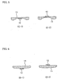
- Figures 3 to 8 schematically illustrate the cross sections of Shapes A to F when viewed from a direction perpendicular to the feeding direction of the copying sheet.
- Figures 3( A -1), 4( B -1), 5( C -1), 6( D -1), 7( E -1), and 8( F -1) show the configuration when the heating element is provided on the fixing face.
- Figures 3( A -2) , 4( B -2), 5( C -2), 6( D -2), 7( E -2), and 8( F -2) show the configuration when the heating element is provided on the reverse side of the fixing face.
- the shapes of the fixing faces of the ceramic heaters are as follows:
- Each heater has a length of 300 mm and a width of 12 mm.
- the ceramic base material having a curved fixing face significantly improves the durability of the heat-resistant film in comparison with the conventional ceramic base material having a rectangular flat-plate shape.
- the samples having Shapes A and B in which the whole fixing face is composed of a circular arc, and the samples having Shapes C and D show no fracture even after 3,000 hours of continuous operation at a rate as high as 40 ppm. These samples have excellent durability.
- the ceramic heater of Sample 5 having Shape B which is thick as a whole, requires slightly higher power consumption, because of its larger thermal capacity.
- the ceramic heater of Sample 9 has Shape C , whose center portion has a minimum thickness of 0.635 mm.
- the heater has a larger thermal capacity than the conventional heater having Shape F , because Shape C has a larger volume caused by the additional circular-arc portion (Shape F has a uniform thickness of 0.635 mm).
- Shape C has a larger volume caused by the additional circular-arc portion (Shape F has a uniform thickness of 0.635 mm).
- the heater requires a longer warming-up time and higher power consumption for fixing the image on a sheet of copying paper.
- ceramic heaters were produced that have Shapes A to F for their fixing faces and that have ceramic base materials comprising silicon nitride or aluminum.
- the silicon nitride ceramic heater the following constituent materials were kneaded: a 100 wt. parts silicon nitride powder; a sintering agent composed of a 5 wt. parts yttrium oxide powder and a 2 wt. parts alumina powder; a binder; and an organic solvent.
- the kneaded body was used to produce formed bodies by a procedure similar to that in Example 1.
- W pastes for a heating element and current-feeding electrodes were screen-printed on the formed body.
- Protective layers were printed with pastes obtained by adding organic solvent and binder to powders having the same composition as the formed body made of silicon nitride.
- the whole bodies were dried, degreased at 800 °C in a nitrogen atmosphere, and sintered at 1,800 °C in a nitrogen atmosphere to complete ceramic heaters made of silicon nitride.
- the silicon nitride ceramic heater had a thermal conductivity of 100 W/(m ⁇ K) and a three-point bending strength of 100 MPa (bending strength was measured in accordance with JIS).
- the following constituent materials were kneaded: a 100 wt. parts alumina powder; a sintering agent composed of a 3 wt. parts magnesium oxide powder, a 2 wt. parts calcium oxide powder, and a 1 wt. parts silicon dioxide powder; a binder; and an organic solvent.
- the kneaded body was used to produce formed bodies by a procedure similar to that in Example 1.
- W pastes for a heating element and current-feeding electrodes were screen-printed on the formed body.
- Protective layers were printed with pastes obtained by adding organic solvent and binder to powders having the same composition as the formed body made of alumina.
- the whole bodies were dried, degreased at 800 °C in a nitrogen atmosphere, and sintered at 1,600 °C in a nitrogen atmosphere to complete ceramic heaters made of alumina.
- the alumina ceramic heater had a thermal conductivity of 20 W/(m ⁇ K) and a three-point bending strength of 40 MPa (the bending strength was measured in accordance with JIS).
- tungsten pastes for the heating element and current-feeding electrodes were screen-printed and a paste having the same composition as each formed body was applied as a protective layer. They were degreased at 800 °C in a nitrogen atmosphere and sintered at 1,800 °C in a nitrogen atmosphere.
- the obtained ceramic heaters made of either silicon nitride or aluminum had a warp of 0.5 mm at the maximum. Although this degree has no adverse effect on the practical use, the degree itself is larger than that of the ceramic heater of the present invention.
Landscapes
- Physics & Mathematics (AREA)
- General Physics & Mathematics (AREA)
- Resistance Heating (AREA)
- Fixing For Electrophotography (AREA)
- Surface Heating Bodies (AREA)
- Control Of Resistance Heating (AREA)
Abstract
Description
| Sample | Base material | Shape of fixing face | Protective layer | Durability of heat-resistant film |
| 1 | AlN | A-1 | AlN | No fracture after 3,000 hrs. |
| 2 | AlN | A-1 | DLC | No fracture after 3,000 hrs. |
| 3 | AlN | A-2 | AlN | No fracture after 3,000 hrs. |
| 4 | AlN | A-2 | DLC | No fracture after 3,000 hrs. |
| 5 | AlN | B-1 | AlN | No fracture after 3,000 hrs. |
| 6 | AlN | B-1 | DLC | No fracture after 3,000 hrs. |
| 7 | AlN | B-2 | AlN | No fracture after 3,000 hrs. |
| 8 | AlN | B-2 | DLC | No fracture after 3,000 hrs. |
| 9 | AlN | C-1 | AlN | No fracture after 3,000 hrs. |
| 10 | AlN | C-1 | DLC | No fracture after 3,000 hrs. |
| 11 | AlN | C-2 | AlN | No fracture after 3,000 hrs. |
| 12 | AlN | C-2 | DLC | No fracture after 3,000 hrs. |
| 13 | AlN | D-1 | AlN | No fracture after 3,000 hrs. |
| 14 | AlN | D-1 | DLC | No fracture after 3,000 hrs. |
| 15 | AlN | D-2 | AlN | No fracture after 3,000 hrs. |
| 16 | AlN | D-2 | DLC | No fracture after 3,000 hrs. |
| 17 | AlN | E-1 | AlN | Fracture after 1,700 hrs. |
| 18 | AlN | E-1 | DLC | Fracture after 1,800 hrs. |
| 19 | AlN | E-2 | AlN | Fracture after 1,800 hrs. |
| 20 | AlN | E-2 | DLC | Fracture after 1,850 hrs. |
| 21 | AlN | F-1 | AlN | Fracture after 1,050 hrs. |
| 22 | AlN | F-1 | DLC | Fracture after 1,150 hrs. |
| 23 | AlN | F-2 | AlN | Fracture after 1,000 hrs. |
| 24 | AlN | F-2 | DLC | Fracture after 1,050 hrs. |
| Sample | Base material | Shape of fixing face | Protective layer layer | Warming-up time (seconds) | Power consumption (Wh) |
| 1 | AlN | A-1 | AlN | 2.2 | 1.36 |
| 5 | AlN | B-1 | AlN | 3.6 | 1.78 |
| 9 | AlN | C-1 | AlN | 3.2 | 1.51 |
| 13 | AlN | D-1 | AlN | 2.0 | 1.25 |
| 17 | AlN | E-1 | AlN | 2.2 | 1.31 |
| 21 | AlN | F-1 | AlN | 2.1 | 1.33 |
| Sample Base Sample | material Base material | Shape of fixing face | Protective | Fixing quality | |
| 1 | AlN | A-1 | AlN | ○ | |
| 2 | AlN | A-1 | DLC | o ○ | |
| 5 | AlN | B-1 | AlN | ○ | |
| 6 | AlN | B-1 | DLC | o ○ |
| Sample | Base material | Shape of fixing face | Protective layer | Durability of heat-resistant film |
| 25 | Al2O3 | A-2 | Al2O3 | No fracture after 3,000 hrs. |
| 26 | Si3N4 | A-2 | Si3N4 | No fracture after 3,000 hrs. |
| 27 | Al2O3 | B-2 | Al2O3 | No fracture after 3,000 hrs. |
| 28 | Si3N4 | B-2 | Si3N4 | No fracture after 3,000 hrs. |
| 29 | Al2O3 | C-2 | Al2O3 | No fracture after 3,000 hrs. |
| 30 | Si3N4 | C-2 | Si3N4 | No fracture after 3,000 hrs. |
| 31 | Al2O3 | D-2 | Al2O3 | No fracture after 3,000 hrs. |
| 32 | Si3N4 | D-2 | Si3N4 | No fracture after 3,000 hrs. |
| 33 | Al2O3 | E-2 | Al2O3 | Fracture after 1,600 hrs. |
| 34 | Si3N4 | E-2 | Si3N4 | Fracture after 1,450 hrs. |
| 35 | Al2O3 | F-2 | Al2O3 | Fracture after 980 hrs. |
| 36 | Si3N4 | F-2 | Si3N4 | Fracture after 920 hrs. |
| Note: Samples 35 and 36 are conventional examples. |
Claims (9)
- A ceramic heater for a toner-fixing unit which unit:(a) comprises:(a1) a heating cylinder provided with a ceramic heater along the longitudinal direction of the outer surface of the cylinder;(a2) a continuous heat-resistant film revolving along the periphery of the heating cylinder; and(a3) a pressure roller that forms a nip portion together with the heat-resistant film at the outer region of the roller opposite to the ceramic heater on the heating cylinder and that rotates to revolve the heat-resistant film at the same speed as the peripheral speed of the pressure roller;(b) feeds a copying sheet to the nip portion by the revolution of the heat-resistant film and the pressure roller; and(c) fixes a toner image on the copying sheet by the pressure of the pressure roller and the heat from the ceramic heater on the heating cylinder;
the ceramic heater comprising:(d) a ceramic base material in which at least one part of the face that contacts the heat-resistant film is curved when viewed from a direction perpendicular to the feeding direction of the copying sheet;(e) a heating element, made of heat-resistant metal or heat-resistant alloy, formed on the ceramic base material; and(f) current-feeding electrodes, made of silver or silver alloy, formed on the ceramic base material. - The ceramic heater as defined in claim 1, wherein the whole of the face that contacts the heat-resistant film forms a circular arc.
- A ceramic heater as defined in claim 1 or 2, wherein the face that contacts the heat-resistant film is provided with an abrasion-resistant protective layer.
- The ceramic heater as defined in claim 3, wherein the abrasion-resistant protective layer comprises ceramic having almost the same composition as the ceramic base material.
- The ceramic heater as defined in claim 3, wherein the abrasion-resistant protective layer comprises diamond-like carbon.
- A ceramic heater as defined in any of claims 1 to 5, wherein the ceramic base material of the ceramic heater comprises an aluminum nitride-based ceramic.
- A ceramic heater as defined in any of claims 1 to 6, wherein the ceramic base material of the ceramic heater comprises a silicon nitride-based ceramic.
- A method for manufacturing a ceramic heater for a toner-fixing unit which unit:(a) comprises:(a1) a heating cylinder provided with a ceramic heater along the longitudinal direction of the outer surface of the cylinder;(a2) a continuous heat-resistant film revolving along the periphery of the heating cylinder; and(a3) a pressure roller that forms a nip portion together with the heat-resistant film at the outer region of the roller opposite to the ceramic heater on the heating cylinder and that rotates to revolve the heat-resistant film at the same speed as the peripheral speed of the pressure roller;(b) feeds a copying sheet to the nip portion by the revolution of the heat-resistant film and the pressure roller; and(c) fixes a toner image on the copying sheet by the pressure of the pressure roller and the heat from the ceramic heater on the heating cylinder;
the method comprising the steps of:(d) extruding a material for a ceramic base material to obtain a formed body in a manner such that at least one part of the ceramic-base-material's face that contacts the heat-resistant film is curved when viewed from a direction perpendicular to the feeding direction of the copying sheet;(e) printing a heating element and current-feeding electrodes with heat-resistant metal pastes or heat-resistant alloy pastes on the formed body at the face where the formed body contacts the heat-resistant film or at the back face; and(f) sintering the formed body with the heating element and the current-feeding electorodes. - The ceramic-heater-manufacturing method as defined in claim 8, wherein the face that contacts the heat-resistant film is provided with an abrasion-resistant protective layer.
Applications Claiming Priority (4)
| Application Number | Priority Date | Filing Date | Title |
|---|---|---|---|
| JP2000136621 | 2000-05-10 | ||
| JP2000136621 | 2000-05-10 | ||
| JP2000239281A JP2002031976A (en) | 2000-05-10 | 2000-08-08 | Ceramic heater for toner fixing device and method of manufacturing the same |
| JP2000239281 | 2000-08-08 |
Publications (3)
| Publication Number | Publication Date |
|---|---|
| EP1154337A2 true EP1154337A2 (en) | 2001-11-14 |
| EP1154337A3 EP1154337A3 (en) | 2002-09-18 |
| EP1154337B1 EP1154337B1 (en) | 2004-12-15 |
Family
ID=26591579
Family Applications (1)
| Application Number | Title | Priority Date | Filing Date |
|---|---|---|---|
| EP01304105A Expired - Lifetime EP1154337B1 (en) | 2000-05-10 | 2001-05-04 | Ceramic heater for toner-fixing units and method for manufacturing the heater |
Country Status (4)
| Country | Link |
|---|---|
| US (1) | US6384378B2 (en) |
| EP (1) | EP1154337B1 (en) |
| JP (1) | JP2002031976A (en) |
| DE (1) | DE60107749D1 (en) |
Families Citing this family (16)
| Publication number | Priority date | Publication date | Assignee | Title |
|---|---|---|---|---|
| JP2002139932A (en) | 2000-11-01 | 2002-05-17 | Sumitomo Electric Ind Ltd | Heat fixing device |
| JP2004286924A (en) * | 2003-03-20 | 2004-10-14 | Minolta Co Ltd | Belt fixing device |
| JP2004286928A (en) * | 2003-03-20 | 2004-10-14 | Minolta Co Ltd | Belt fixing device |
| JP4206788B2 (en) * | 2003-03-20 | 2009-01-14 | コニカミノルタビジネステクノロジーズ株式会社 | Belt fixing device |
| US6879803B2 (en) * | 2003-04-29 | 2005-04-12 | Lexmark International, Inc. | Belt fuser for a color electrophotographic printer |
| US6865351B2 (en) * | 2003-04-29 | 2005-03-08 | Lexmark International, Inc. | Method of using a fuser for a color electrophotographic printer |
| US7466951B2 (en) * | 2004-09-29 | 2008-12-16 | Lexmark International, Inc. | Heater assembly in a fuser with a raised resilient pad in an electrophotographic imaging device |
| JP2009258517A (en) * | 2008-04-18 | 2009-11-05 | Sharp Corp | Fixing device and image forming apparatus including the same |
| JP2010191217A (en) * | 2009-02-18 | 2010-09-02 | Sharp Corp | Fixing device, image forming apparatus, recording medium recording control program for realizing fixing device, and control method for fixing device |
| JP5428920B2 (en) * | 2010-02-15 | 2014-02-26 | 株式会社リコー | Fixing device and image forming apparatus |
| JP5407951B2 (en) * | 2010-03-15 | 2014-02-05 | コニカミノルタ株式会社 | Fixing apparatus and image forming apparatus |
| US8670012B2 (en) * | 2011-06-28 | 2014-03-11 | Kabushiki Kaisha Toshiba | Erasing apparatus and erasing method |
| JP6198580B2 (en) * | 2013-11-18 | 2017-09-20 | キヤノン株式会社 | Image heating apparatus and image forming apparatus equipped with the image heating apparatus |
| CN107526273B (en) | 2016-06-20 | 2021-05-11 | 东芝泰格有限公司 | Heater, fixing device, and image forming device |
| US11262680B2 (en) | 2020-04-21 | 2022-03-01 | Canon Kabushiki Kaisha | Heat fixing device, electrophotographic image forming apparatus, and laminated structural body |
| JP2025047373A (en) * | 2023-09-21 | 2025-04-03 | 東芝ライテック株式会社 | Heater, and image forming apparatus |
Family Cites Families (16)
| Publication number | Priority date | Publication date | Assignee | Title |
|---|---|---|---|---|
| JP2516886B2 (en) | 1987-06-16 | 1996-07-24 | キヤノン株式会社 | Image heating device |
| JP2673959B2 (en) | 1988-04-15 | 1997-11-05 | キヤノン株式会社 | Fixing device |
| JP2646444B2 (en) | 1988-12-12 | 1997-08-27 | キヤノン株式会社 | Image heating fixing device |
| JP3155066B2 (en) * | 1992-06-17 | 2001-04-09 | キヤノン株式会社 | Fixing device |
| JPH06118829A (en) * | 1992-10-02 | 1994-04-28 | Fuji Xerox Co Ltd | Local heating device and device equipped with the same |
| JPH06202512A (en) * | 1992-12-29 | 1994-07-22 | Canon Inc | Heating device and image recorder |
| JPH07295409A (en) * | 1994-04-25 | 1995-11-10 | Canon Inc | Heating/fixing device and manufacture thereof |
| JPH0980940A (en) | 1995-09-07 | 1997-03-28 | Canon Inc | Heating device |
| JPH09197861A (en) | 1995-11-13 | 1997-07-31 | Sumitomo Electric Ind Ltd | Heater and heat fixing device having the same |
| JP3372811B2 (en) * | 1997-02-03 | 2003-02-04 | キヤノン株式会社 | Heat fixing device |
| JPH1195583A (en) * | 1997-09-17 | 1999-04-09 | Sumitomo Electric Ind Ltd | Ceramic heater for fixing toner image |
| DE69904793T2 (en) * | 1998-10-13 | 2003-10-02 | Canon K.K., Tokio/Tokyo | Arrangements for heat fixation with an elastic, thermally highly conductive layer |
| US6276793B1 (en) * | 1998-11-02 | 2001-08-21 | Xerox Corporation | Ink jet printer having a wear resistant and efficient substrate heating and supporting assembly |
| JP2000250340A (en) * | 1999-02-26 | 2000-09-14 | Canon Inc | Fixing device and image forming device |
| US6122478A (en) * | 1999-08-04 | 2000-09-19 | Hewlett-Packard Company | Reduction of thermally induced mechanical stress in a fixing device |
| US6157806A (en) * | 2000-01-27 | 2000-12-05 | Lexmark International, Inc. | Fuser system with greased belt |
-
2000
- 2000-08-08 JP JP2000239281A patent/JP2002031976A/en active Pending
-
2001
- 2001-04-16 US US09/834,642 patent/US6384378B2/en not_active Expired - Fee Related
- 2001-05-04 DE DE60107749T patent/DE60107749D1/en not_active Expired - Lifetime
- 2001-05-04 EP EP01304105A patent/EP1154337B1/en not_active Expired - Lifetime
Also Published As
| Publication number | Publication date |
|---|---|
| EP1154337A3 (en) | 2002-09-18 |
| US6384378B2 (en) | 2002-05-07 |
| JP2002031976A (en) | 2002-01-31 |
| US20010054609A1 (en) | 2001-12-27 |
| EP1154337B1 (en) | 2004-12-15 |
| DE60107749D1 (en) | 2005-01-20 |
Similar Documents
| Publication | Publication Date | Title |
|---|---|---|
| US6392197B2 (en) | Ceramic heater for toner-fixing units and method for manufacturing the heater | |
| EP1154337B1 (en) | Ceramic heater for toner-fixing units and method for manufacturing the heater | |
| US5732318A (en) | Heater and heating/fixing unit comprising the same | |
| EP0838734B1 (en) | Heat fixing device | |
| US20200285179A1 (en) | Heater, fixing device, and image forming apparatus | |
| EP1243981A1 (en) | Thermal fixing apparatus | |
| JP2002214951A (en) | Heating resistor sheet for fixing and fixing device | |
| JP5605670B2 (en) | Fixer assembly, xerographic device, and method for fixing toner on media | |
| KR100388862B1 (en) | Ceramic Settling Heater Containing Silicon Nitride | |
| CN118534746A (en) | Heater, heating device and imaging device | |
| JP2005165291A (en) | Endless metal belt, fixing belt, and heat fixing device | |
| JP3924831B2 (en) | Ceramic heater and heat fixing device | |
| JP2009042417A (en) | Plate heater, heating device, image forming device | |
| JP2004158246A (en) | Heating equipment | |
| JPH11174875A (en) | Heating and fixing device | |
| JP2009064658A (en) | Heating member and image heating apparatus having the heating member | |
| JP2004102232A (en) | Fixing roller, and fixing device equipped with fixing roller | |
| JP2004102231A (en) | Fixing roller and fixing device equipped with the fixing roller | |
| JP2009139460A (en) | Heating member and image heating apparatus having the heating member | |
| JP3933171B2 (en) | Heat fixing device | |
| JPH11174874A (en) | Thermal fixing device | |
| JPH11296005A (en) | Thermal fixing device | |
| CN115469520A (en) | Fixing device and image forming equipment | |
| JP2025083514A (en) | Heater and image heating device including the same | |
| JP2023070429A (en) | Heaters, heating devices and image forming devices |
Legal Events
| Date | Code | Title | Description |
|---|---|---|---|
| PUAI | Public reference made under article 153(3) epc to a published international application that has entered the european phase |
Free format text: ORIGINAL CODE: 0009012 |
|
| AK | Designated contracting states |
Kind code of ref document: A2 Designated state(s): AT BE CH CY DE DK ES FI FR GB GR IE IT LI LU MC NL PT SE TR |
|
| AX | Request for extension of the european patent |
Free format text: AL;LT;LV;MK;RO;SI |
|
| PUAL | Search report despatched |
Free format text: ORIGINAL CODE: 0009013 |
|
| AK | Designated contracting states |
Kind code of ref document: A3 Designated state(s): AT BE CH CY DE DK ES FI FR GB GR IE IT LI LU MC NL PT SE TR |
|
| AX | Request for extension of the european patent |
Free format text: AL;LT;LV;MK;RO;SI |
|
| RIC1 | Information provided on ipc code assigned before grant |
Free format text: 7G 03G 15/20 A, 7H 05B 3/14 B, 7H 05B 3/00 B |
|
| 17P | Request for examination filed |
Effective date: 20021216 |
|
| 17Q | First examination report despatched |
Effective date: 20030401 |
|
| AKX | Designation fees paid |
Designated state(s): DE FR GB IT |
|
| GRAP | Despatch of communication of intention to grant a patent |
Free format text: ORIGINAL CODE: EPIDOSNIGR1 |
|
| GRAS | Grant fee paid |
Free format text: ORIGINAL CODE: EPIDOSNIGR3 |
|
| GRAA | (expected) grant |
Free format text: ORIGINAL CODE: 0009210 |
|
| AK | Designated contracting states |
Kind code of ref document: B1 Designated state(s): DE FR GB IT |
|
| PG25 | Lapsed in a contracting state [announced via postgrant information from national office to epo] |
Ref country code: IT Free format text: LAPSE BECAUSE OF FAILURE TO SUBMIT A TRANSLATION OF THE DESCRIPTION OR TO PAY THE FEE WITHIN THE PRESCRIBED TIME-LIMIT;WARNING: LAPSES OF ITALIAN PATENTS WITH EFFECTIVE DATE BEFORE 2007 MAY HAVE OCCURRED AT ANY TIME BEFORE 2007. THE CORRECT EFFECTIVE DATE MAY BE DIFFERENT FROM THE ONE RECORDED. Effective date: 20041215 Ref country code: FR Free format text: LAPSE BECAUSE OF FAILURE TO SUBMIT A TRANSLATION OF THE DESCRIPTION OR TO PAY THE FEE WITHIN THE PRESCRIBED TIME-LIMIT Effective date: 20041215 |
|
| REG | Reference to a national code |
Ref country code: GB Ref legal event code: FG4D |
|
| REG | Reference to a national code |
Ref country code: IE Ref legal event code: FG4D |
|
| REF | Corresponds to: |
Ref document number: 60107749 Country of ref document: DE Date of ref document: 20050120 Kind code of ref document: P |
|
| PG25 | Lapsed in a contracting state [announced via postgrant information from national office to epo] |
Ref country code: DE Free format text: LAPSE BECAUSE OF FAILURE TO SUBMIT A TRANSLATION OF THE DESCRIPTION OR TO PAY THE FEE WITHIN THE PRESCRIBED TIME-LIMIT Effective date: 20050316 |
|
| PLBE | No opposition filed within time limit |
Free format text: ORIGINAL CODE: 0009261 |
|
| STAA | Information on the status of an ep patent application or granted ep patent |
Free format text: STATUS: NO OPPOSITION FILED WITHIN TIME LIMIT |
|
| 26N | No opposition filed |
Effective date: 20050916 |
|
| EN | Fr: translation not filed | ||
| PGFP | Annual fee paid to national office [announced via postgrant information from national office to epo] |
Ref country code: GB Payment date: 20090429 Year of fee payment: 9 |
|
| GBPC | Gb: european patent ceased through non-payment of renewal fee |
Effective date: 20100504 |
|
| PG25 | Lapsed in a contracting state [announced via postgrant information from national office to epo] |
Ref country code: GB Free format text: LAPSE BECAUSE OF NON-PAYMENT OF DUE FEES Effective date: 20100504 |