EP1154270A2 - Glycated hemoglobin analyzer - Google Patents
Glycated hemoglobin analyzer Download PDFInfo
- Publication number
- EP1154270A2 EP1154270A2 EP01111098A EP01111098A EP1154270A2 EP 1154270 A2 EP1154270 A2 EP 1154270A2 EP 01111098 A EP01111098 A EP 01111098A EP 01111098 A EP01111098 A EP 01111098A EP 1154270 A2 EP1154270 A2 EP 1154270A2
- Authority
- EP
- European Patent Office
- Prior art keywords
- flow passage
- containers
- pump
- sample
- glycated hemoglobin
- Prior art date
- Legal status (The legal status is an assumption and is not a legal conclusion. Google has not performed a legal analysis and makes no representation as to the accuracy of the status listed.)
- Granted
Links
Images


Classifications
-
- G—PHYSICS
- G01—MEASURING; TESTING
- G01N—INVESTIGATING OR ANALYSING MATERIALS BY DETERMINING THEIR CHEMICAL OR PHYSICAL PROPERTIES
- G01N30/00—Investigating or analysing materials by separation into components using adsorption, absorption or similar phenomena or using ion-exchange, e.g. chromatography or field flow fractionation
- G01N30/02—Column chromatography
- G01N30/04—Preparation or injection of sample to be analysed
- G01N30/16—Injection
- G01N30/20—Injection using a sampling valve
-
- G—PHYSICS
- G01—MEASURING; TESTING
- G01N—INVESTIGATING OR ANALYSING MATERIALS BY DETERMINING THEIR CHEMICAL OR PHYSICAL PROPERTIES
- G01N30/00—Investigating or analysing materials by separation into components using adsorption, absorption or similar phenomena or using ion-exchange, e.g. chromatography or field flow fractionation
- G01N30/02—Column chromatography
- G01N30/88—Integrated analysis systems specially adapted therefor, not covered by a single one of the groups G01N30/04 - G01N30/86
- G01N2030/8809—Integrated analysis systems specially adapted therefor, not covered by a single one of the groups G01N30/04 - G01N30/86 analysis specially adapted for the sample
- G01N2030/8813—Integrated analysis systems specially adapted therefor, not covered by a single one of the groups G01N30/04 - G01N30/86 analysis specially adapted for the sample biological materials
- G01N2030/8822—Integrated analysis systems specially adapted therefor, not covered by a single one of the groups G01N30/04 - G01N30/86 analysis specially adapted for the sample biological materials involving blood
-
- G—PHYSICS
- G01—MEASURING; TESTING
- G01N—INVESTIGATING OR ANALYSING MATERIALS BY DETERMINING THEIR CHEMICAL OR PHYSICAL PROPERTIES
- G01N33/00—Investigating or analysing materials by specific methods not covered by groups G01N1/00 - G01N31/00
- G01N33/48—Biological material, e.g. blood, urine; Haemocytometers
- G01N33/50—Chemical analysis of biological material, e.g. blood, urine; Testing involving biospecific ligand binding methods; Immunological testing
- G01N33/72—Chemical analysis of biological material, e.g. blood, urine; Testing involving biospecific ligand binding methods; Immunological testing involving blood pigments, e.g. haemoglobin, bilirubin or other porphyrins; involving occult blood
Definitions
- the present invention relates to a glycated hemoglobin analyzer using a liquid chromatography.
- a conventional glycated hemoglobin analyzer includes a separation column for separating a hemoglobin component, a detector for detecting a separated component, a liquid supplying pump for supplying an eluent, a sampling part for supplying a sample to be analyzed to an analyzer, and the like.
- a clinical inspection equipment such as a glycated hemoglobin analyzer
- a blood specimen collection tube containing collectedblood is directly set to the analyzer, and then the analyzer automatically picks up and analyzes the sample.
- a subject to be analyzed is a hemoglobin in a red blood cell.
- the hemoglobin is contained at high concentration in blood. Therefore, it is impossible to directly subject it to the liquid chromatography analysis. Accordingly, upon analyzing it, it is necessary to dilute the blood sample with about 100 times in advance. For this reason, in the glycated hemoglobin analyzer, it is a common practice that a trace of blood of several micro liters is collected, it is automatically diluted in the analyzer, and then it is analyzed.
- a sampling part is used, which is structured by a syringe unit for sucking and discharging a sample and a wash and hemolysis solution and a flow passage change-over mechanism combined with a plurality of 2- or 3-way electromagnetic valves, both being controlled by a control means (CPU) of the analyzer.
- CPU control means
- the flow passages arrangement is complicated because of the combination of the plural electromagnetic valves.
- the electromagnetic valve contains movable parts therein, it contains many locations to be maintained.
- the flow passage is more increased in its length. Accordingly, the dead volume within the flow passage is large. This fact makes it difficult to reduce an air capacity within the flow passage extending between the syringe and the sample liquid surface. As a result, the precious sample loss is great, and it is difficult to suck an exact amount of the sample.
- the syringe and the electromagnetic valves may be connected by use of flow passages are small in inside diameter.
- the suction resistance by the flow passage is large, and thus the suction velocity is hindered, and the suction accuracy is degraded.
- the difficulty of increasing the suction velocity also hinders an attempt to increase the operation speed of the whole sampling mechanism with the intention of reducing the analyzing time per sample.
- an object of the present invention is to provide a glycated hemoglobin analyzer which is provided with a flow passage change-over mechanism which can form a flow passage by use of only a single flow passage change-over valve of the rotary type, without using an electromagnetic valve, whereby the analyzer is capable of operating, at high speeds, a pump for sucking and discharging a sample and a wash and hemolysis solution at each step of sampling, and a time taken for a pretreatment for each sample is remarkably reduced.
- a glycated hemoglobin analyzer using a liquid chromatography having a separation column for separating a hemoglobin component, a detector for detecting a separated component, a liquid supplying pump for supplying an eluent, and a sampling part for supplying a sample to be analyzed to an analyzing part, characterized in that the sampling part being constructed with a flow passage change-over mechanism constructed such that a flow passage is formed by use of a flow passage change-over valve of the rotary type.
- This flow passage change-over mechanism is a non-electromagnetic-type valve, not using an electromagnetic valve.
- the rotary type flow passage change-over valve used in the flow passage change-over mechanism of the invention may be any valve flow passage change-over valve, which utilizes a rotary valve, and includes more than three ports capable of connecting flow passages, and operates such that with rotation of the valve, a flow passage connection mechanism, called a rotary seal, interlockingly rotates to interconnect flow passages connecting to the valve and disconnect them from each other.
- the number of flow passages that may be connected to the valve is at least three.
- the flow passage change-over mechanism is assembled into the sampling mechanism to form flow passages for operations including operations of diluting the sample, cleaning the sampling needle and the like, more than six flow passages may be connected to the valve. In this case, it is preferable that one flow passage is connected to one of the remaining five flow passages or more (this one flow passage will frequently be denoted as (A) ⁇ .
- the flow passage change-over mechanism of the invention may be rearranged into a sampling mechanism for sucking and discharging samples and a wash and hemolysis solution when it is connected to drive means for sampling, such as a cylinder pump or a peristaltic pump, which is used by a general liquid chromatography apparatus.
- drive means for sampling such as a cylinder pump or a peristaltic pump, which is used by a general liquid chromatography apparatus.
- the flow passage change-over mechanism which is connected to the sampling drive means, is further connected to the sampling needle, a dilution liquid supply flow passage, a cleaning liquid supply flow passage, a dilution block, a waste liquid discharging flow passage and the like, it may be used as the auto sampler mentioned above.
- the sampling drive means In order to simplify the structure of the whole sampling mechanism, it is effective to connect the sampling drive means to the flowpassage (A) .
- the rotary valve in the flow passage change-over mechanism may be driven in an desired manner.
- it may be driven manually or automatically by using the motor.
- it is preferable that it is automatically driven by using the motor.
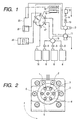
- Fig. 1 is a diagram schematically showing a glycated hemoglobin analyzer constructed according to the present invention.
- the glycated hemoglobin analyzer includes an eluent 8, an eluent change-over electromagnetic valve 9, an eluent mixing block 10, an eluent supplying pump (a glycated hemoglobin analyzer pump) 11, a sample injection valve 12, a line filter 13, an analyzing column 14, a detector 15, a wash and hemolysis solution 16, a flow passage switch-over valve (a rotary valve) 17, a syringe pump 18, a micro-syringe pump 19, a sampling needle 20, a needle cleaning block 21, and a dilution block 22.
- a glycated hemoglobin analyzer includes an eluent 8, an eluent change-over electromagnetic valve 9, an eluent mixing block 10, an eluent supplying pump (a glycated hemoglobin analyzer pump) 11, a sample injection valve 12, a
- the flow-passage switchover valve 17 is connected to the syringe pump 18, the wash and hemolysis solution part 16, the needle cleaning block 21, the dilution block 22, the sampling needle 20, the eluent supplying pump 11, and the eluent mixing block 10, whereby a flow passage change-over mechanism is formed.
- Glycohemoglobin is measured in a manner that ablood sample is diluted with about 100 times by a dilution liquid, and then is separated by an ion exchanging chromatography. An operation of a sampling mechanism in the measurement will be described in successive order.
- the rotary valve 17 is rotated to connect a port 1 to a port 7.
- the sampling needle 20 is put into the blood sample, and the syringe pump 18 is driven, so that a fixed amount of blood is sucked into the sampling needle 20.
- the rotary valve 17 is rotated to connect a port 4 to the port 7. Firstly, the syringe pump 18 is driven to suck a fixed amount of a wash and hemolysis solution 8 into the syringe.
- the rotary valve 17 is rotated to connect a port 6 to the port 7.
- the wash and hemolysis solution that has been sucked into the syringe flows to the needle cleaning block 21, so as to wash away the excessive blood sample attached to the outer wall of the needle.
- the rotary valve 17 is rotated to connect the ports 4 and 7. Then, as in the previous case, the wash and hemolysis solution 8 is sucked into the syringe. Then, the rotary valve 17 is rotated to connect the ports 1 and 7, so that the blood sample of the needle, together with the wash and hemolysis solution 8 that has been sucked into the syringe, is discharged into the dilution block 22. Further, the sucking/discharging operation by the syringe pump 18 is repeated two or three times. As a result, the wash and hemolysis solution 8 and the blood in the dilution block 22 are sucked and discharged to mix them uniformly.
- the diluted sample in the dilution block 22 is introduced into the analyzer through the sample injection valve 12.
- a fixed-amount introducing valve is formed with a sampling probe and an injection valve connected to the sampling probe.
- the inside of the sampling needle 20 and the dilution block 22 are washed out using the wash and hemolysis solution.
- the rotary valve 17 is turned to connect the ports 4 and 7.
- the syringe pump 18 is driven to suck the wash and hemolysis solution from the syringe.
- the rotary valve 17 is driven to connect the ports 1 and 7, whereby the wash and hemolysis solution in the syringe is discharged from the sampling needle 20.
- the inner wall of the sampling needle 20 is washed out by the wash and hemolysis solution, and filled with the same.
- the rotary valve 17 is rotated again to connect the ports 2 and 7, so that the wash and hemolysis solution filling the syringe is discharged into the dilution block 22.
- the dilution block has an overflow structure. The wash and hemolysis solution containing the diluted sample are completely discharged, so that the dilution block 22 is filled with the wash and hemolysis solution.
- Fig. 2 is a diagram showing an overall rotary valve available for the present invention.
- This rotary valve includes seven ports for interconnecting flow passages. With rotation of a rotor within the valve in directions of arrows, the center port 7 is connected to one of the remaining six ports 1 to 6.
- Fig. 3 is a side view showing a portion of a main body 23 of the rotary valve 17 of Fig. 2 and a pulse motor 25 connected to the main body 23 via a fixing member 26.
- the pulse motor 25 is connected along an elongation of the valve rotary shaft.
- the pulse motor 25 is controlled by an external control unit to turn the valve at a desired angle in conjunction with a rotating position detecting sensor 24, whereby the center port 7 is connected to a desired port of the remaining ones 1 to 6.
- Fig. 4 is a sectional view showing an inner structure of the rotary valve 17.
- a rotor seal 29 having a groove 28 extended in only one direction is installed behind a stator 27 for connecting the flow passages.
- the rotary valve thus constructed is commercially available (from, for example, Rheodyne corporation in U.S.A.). It is evident that any other suitable valve having the inner structure different from that of the Fig. 4 may be used for the rotary valve of the invention.
- Figs. 5 and 6 show a example of a plunger pump adaptable for the glycated hemoglobin analyzer pump 11 according to the invention.
- a rotating motion of the motor is converted into a reciprocal motion of a plunger 49 by use of a mechanism including a camand the like.
- the reciprocating plunger 49 its tip is reciprocatively moved within a pump head 50, through a plunger seal 36.
- the inner volume of the pump head 50 increases and decreases in accordance with the reciprocative motion of the plunger 49.
- Check valves 30, 31 are provided at the inlet and the outlet of the pump head 50. With a volume variation, the liquid flows from the inlet to the outlet. In this way, the plunger pump feeds the liquid.
- the cleaning liquid which is used for washing the sampling part.
- a liquid containing refined water and a small amount of surfactant e.g., TritonX-100 of about 0.01%(V/V)
- This solution is also used for the cleaning liquid for the plunger pump.
- the solution is supplied through the sampling part.
- liquid feeding means such as a cylinder pump in the sampling part is used for the liquid feeding.
- Fig. 5 is a cross sectional view showing the plunger pump.
- the liquid to be fed flows through a check valve 30 and flows out through a check valve 31.
- cleaning liquid passage tubes 32 and 33 are further coupled thereto.
- Fig. 6 is an enlarged view showing a portion indicated as A in Fig. 5.
- a portion in which the cleaning liquid flows is a space indicated by reference numeral 34.
- the space 34 is separated from a plunger operation mechanism on the right in the drawing by a diaphragm 35, and from the flow passage for the analysis by a plunger seal 36, thereby preventing the cleaning liquid from flowing out of the cleaning liquid passage tubes 32 and 33.
- Fig. 7 is a diagram for explaining in detail the cleaning method mentioned above.
- the flow passage to be connected to the cylinder pump 37 is selected by a rotary valve 38.
- a cleaning liquid 39 is first sucked by the cylinder pump 37, then the flow passage is switched over to the pump washing line via the port 5, the sucked cleaning liquid passes through the pump washing line to wash out a pump 40, and then is discharged outside.
- it is satisfactory that such a cleaning operation is executed when the analyzer is started and ended. Accordingly, the cleaning operation is not performed when the analyzing operation is performed, and the washing line may be filled with the cleaning liquid.
- the analyzer of the invention handles the blood sample, in order to prevent the operator from being infected with virus and the like, it is preferable that a collected blood is not transferred from the blood specimen collection tube to a sample container specially prepared, and the blood specimen collection tube is utilized as the sample container as it is. Specifically, those tubes are set in a rack as shown in Fig. 8, and are continuously or intermittently transported to the sampling part of the invention.
- a standard sample and a control sample are also used for the calibration of the analyzer and its accuracy management.
- Polypropylene containers of 1 to 2ml in volume, which are different from the sample collection tubes, are usually used for containing the standard sample or the control sample.
- an injector not the usual blood collection tube, is used for collecting blood, and the collected blood is put in the container of a small volume as mentioned above, and disposed on the rack.
- containers containing the blood sample are set in the rack, and are transported to the sampling part. Then, a fixed amount of blood sample necessary for the measurement is sucked in accordance with a predetermined operation sequence, and is subjected to the analysis.
- the blood collection tube and the polypropylene container of about 1 to 2ml are different in size and shape. If those tube and containers are transported while randomly arranged, the following problem arises. Those tubes and containers are different in the liquid level of the sample and the opening-to-bottom distance from each other. This fact hinders operation sequences of the descending control of the sample suction nozzle and the like.
- the present invention also provides an analyzer which is capable of automatically carrying out the analysis by equipping with a transporting means such a rack and a sample container identifying device as shown in Figs. 9 and 10.
- Figs. 9 and 10 show diagrams as viewed from this side when the sample container identifying device is viewed in the rack transporting direction.
- the sample container identifying device includes a rack 41, a container (blood collection tube) 43 disposed on the rack 41, and two actuator type micro-switches 44, 45. Those micro-switches 44, 45 are located at different mounting positions for discriminating a height difference of a part of the container, which is projected above the rack body.
- the two micro-switches are vertically disposed one on the other at different height positions (viewed in the direction orthogonal to the container transporting direction), whereby the containers being transported can instantaneously be identified.
- Those micro-switches 44, 45 are in an off (on) state when the sample container is not set in the rack.
- the actuator 46, 47 is inclined at about 30° or larger with respect to the horizontal direction, the micro-switches 44, 45 are turned on (off).
- the rack When the rack is transported and the sample containers set on the rack reaches a position at which the micro-switches are mounted, if the transported sample container 43, the height of the part of which is projected above the rack bodybeinghigher than another sample container 48 is transported, the two micro-switches 44, 45 are both turned on (off). In addition, if the transported sample container 43, the height of the part of which is projected above the rack body being lower than another sample container 48 is transported, the lower micro-switch 45 of those micro-switches are both turned on (off), while the upper micro-switch 44 remains off (on).
- the blood collection tube corresponds to the sample container 43
- a commercially available sample cup (used for the Hitachi automatic analyzer 703) corresponds to the sample container 48. Therefore, on the basis of the observation of the output signals from the two micro-switches, one detects whether the transported container is the sample container 43 or the sample container 48, or the container is set in the rack or not. Accordingly, the analyzer is controlled by the output signals so as to start a predetermined operation sequence.
- the micro-switches illustrated may be mounted on the lower side of the rack if the rack is so configured.
- Fig. 11 shows how to identify the container shown in Figs . 9 and 10 when it is viewed from the rear side of the device (the sample container identifying device per is illustrated while being turned by 90°).
- an arrow indicates an advancing direction of the rack 41.
- the micro-switches which have actuators equal to or larger than the number of the kinds of containers to be identified.
- An n-number of kinds of containers can be identified by using an (n - 1) number of micro-switches. If an "n" number of micro-switches or larger are used, an "n” number of kinds of containers can be identified, and further whether or not the container is set in the rack can also be detected. Description will be given about a case that at least two micro-switches are used in a fixed state, while sample containers are transported. As an example, there are considered two cases.
- micro-switches are serially arranged in the same direction as the sample container transporting direction, and those containers are identified after all those containers pass in the front of the micro-switches.
- the other is that those micro-switches are arranged in the direction vertical to the container transporting direction, and the transporting containers are instantaneously identified.
- the latter arrangement of the micro-switches is used and the containers are instantaneously identified, in order to secure the size reduction of the sample container identifying device and the simplification of the operation sequence of the whole analyzer.
- the sample container identifying device actuator type micro-switches
- actuator type micro-switches a position at which one discriminates the containers in size and configuration is determined based on the kinds of the containers to be set in the rack, and any special limitation is not put in particular.
- actuator type micro-switches are mounted at different height positions, and a height of the part of the container projected above the rack body and a diameter of the container are discriminately detected.
- Actuator type micro-switches are not limited in particular if those are turned on and off depending on the size and/or configuration of the containers to be set (or to probably be set) in the rack or depending on whether or not the container is present. But, Of those actuator type micro-switches, the micro-switches of the lever type or the small torque rotation type are preferably used in order to secure the well adaptability and easy adjustment for various sizes and configurations of the containers.
- the micro-switches of the lever type may be a commercially available one (e.g., SS-01 type micro-switch, trade name, manufactured by Omron corporation).
- the micro-switches of the small torque rotation type may be a commercially available one (e.g., D2MC type micro-switch, trade name, manufactured by Omron corporation).
- a rack being capable of receiving only one container or a plurality of containers may be used.
- a rack capable of receiving one or a plurality of vacuum blood collection tube for collecting a blood sample. It is marketed as the Sysmex standard rack, manufactured by Sysmex corporation. This rack is capable of receiving one to ten blood collection tubes of 12 to 15 mm in diameter, and containers resembling them.
- the racks described above are all of the type in which the sample containers received are linearly arranged. If required, the rack of the type in which the containers received, like a turntable, are circularly arranged may be used.
- the container to be identified by the sample container identifying means may be any suitable one if it is capable of holding the sample, in addition to the polypropylene container and the vacuum blood collection tube.
- An example of the container adaptable for the marketed rack is a vacuum blood collection tube of 75 to 100mm in height and 12 to 15mm in diameter.
- Such a vacuum blood collection container may commercially be available as VENOJECT II, trade name, manufactured by Terumo corporation.
- a sample cup for Hitachi automatic analyzer 703, ⁇ 17 x 38mm, manufactured by UNIFLEX Co, Ltd. may also be enumerated.
- the containers are moved so as to turn on or off the actuator type micro-switches installed to the sample container identifying device.
- the sample container identifying device (actuator type micro-switches) are moved so that those are turned on or off by the container.
- the sample containers and the sample container identifying device (actuator type micro-switches) are moved relative to each other so that the actuator type micro-switches are turned on and off by the containers.
- the sample container identifying device of the invention is fixed, and the actuator type micro-switches of the sample container identifying device are turned on and off by the containers set in the rack through the movement of the rack.
- the movement of the rack and/or the sample container identifying device may be continuous or intermittent. Use of the intermittent movement is preferable to secure an easy control of the overall analyzer. An example of the control is to select appropriate operation sequences for different sample sucking nozzles, and to start the selected sequential operations.
- the invention employs the rotary valve in place of the combination of the electromagnetic valves . Accordingly, the glycated hemoglobin analyzer with the flow passage switch-over mechanism, which realizes a higher accurate sampling than the conventional one, is capable of operating, at high speeds, the pump for sucking and discharging the blood samples and the wash and hemolysis solution at the respective sampling stages, and remarkably reducing the time taken for the pretreatment per sample.
Landscapes
- Physics & Mathematics (AREA)
- Health & Medical Sciences (AREA)
- Life Sciences & Earth Sciences (AREA)
- Chemical & Material Sciences (AREA)
- Analytical Chemistry (AREA)
- Biochemistry (AREA)
- General Health & Medical Sciences (AREA)
- General Physics & Mathematics (AREA)
- Immunology (AREA)
- Pathology (AREA)
- Automatic Analysis And Handling Materials Therefor (AREA)
Abstract
Description
Claims (10)
- A glycated hemoglobin analyzer using a liquid chromatography, comprising:characterized in that:a separation column (14) for separating a hemoglobin component;a detector (15) for detecting the separated component;a liquid supplying pump (11, 40) for supplying an eluent; anda sampling part (17, 18, 37, 38) for supplying a sample to be analyzed to an analyzing part,
said sampling part (17, 18, 37, 38) is constructed with a flow passage change-over mechanism constructed such that a flow passage is formed by a changeover of a flow passage change-over valve of the rotary type (17, 38), said flow passage change-over valve being a non-electromagnetic valve type. - The glycatedhemoglobin analyzer according to claim 1, wherein said flow passage change-over valve (17,38) has at least three ports (1, 2, 3, 4, 5, 6, 7), and said flow passage change-over valve (17,38) is changed over to connect said two ports (1, 2, 3, 4, 5, 6, 7) to thereby form the flow passage.
- The glycated hemoglobin analyzer according to claim 2, wherein said sampling part (17, 18, 37, 38) includes a syringe pump (18, 37) connected to said port (7) of said flow passage change-over valve (17, 38).
- The glycatedhemoglobin analyzer according to claim 1, wherein said liquid supplying pump (11, 40) is a plunger pump including a pump head (50), a plunger (49) reciprocating within said pump head (50) through a plunger seal (36) and a partitioned chamber (34) separated from said pump head (50) by said plunger seal (36), and
the confronting surfaces of said plunger (49) and said plunger seal(36) are washed out by feeding a cleaning liquid to said partitioned chamber (34). - The glycated hemoglobin analyzer according to claim 4, wherein said liquid supplying pump (11, 40) is washed out by feeding the cleaning liquid through said flow passage change-over valve (17, 38).
- The glycated hemoglobin analyzer according to claim 4, wherein said sampling part (17, 18, 37, 38) includes a syringe pump (18, 37) connected to one of ports (1, 2, 3, 4, 5, 6, 7) of said flow passage change-over valve (17, 38),
wherein said liquid supplying pump (11, 40) is washed out by feeding the cleaning liquid by said syringe pump (18, 37) through the flow passage change-over valve (17, 38). - The glycated hemoglobin analyzer according to claim 1, further comprising:a sample container identifying device for identifying containers (43, 48) set in a rack (41), said sample container identifying device including actuator type micro-switches (44, 45), the number of which is equal or more than the number of kinds of containers (43, 48) to be identified,wherein the kinds of said containers (43, 48) are identified through the on and off states of said actuator type micro-switches (44, 45).
- The glycated hemoglobin analyzer according to claim 7, wherein said sample container identifying device identifies the kinds of said containers (43, 48) during the intermittent movement of said containers (43, 48) set in the rack (41).
- The glycated hemoglobin analyzer according to claim 7, wherein said sample container identifying device identifies the kinds of said containers on the basis of the height difference of said containers (43, 48) set in the rack (41).
- The glycated hemoglobin analyzer according to claim 7, wherein the kinds of said containers tobe identified includes a blood collection tube.
Applications Claiming Priority (8)
| Application Number | Priority Date | Filing Date | Title |
|---|---|---|---|
| JP2000142264 | 2000-05-09 | ||
| JP2000142265 | 2000-05-09 | ||
| JP2000142266 | 2000-05-09 | ||
| JP2000142263 | 2000-05-09 | ||
| JP2000142266 | 2000-05-09 | ||
| JP2000142265 | 2000-05-09 | ||
| JP2000142264 | 2000-05-09 | ||
| JP2000142263 | 2000-05-09 |
Publications (3)
| Publication Number | Publication Date |
|---|---|
| EP1154270A2 true EP1154270A2 (en) | 2001-11-14 |
| EP1154270A3 EP1154270A3 (en) | 2004-04-28 |
| EP1154270B1 EP1154270B1 (en) | 2015-01-21 |
Family
ID=27481292
Family Applications (1)
| Application Number | Title | Priority Date | Filing Date |
|---|---|---|---|
| EP20010111098 Expired - Lifetime EP1154270B1 (en) | 2000-05-09 | 2001-05-09 | Glycated hemoglobin analyzer |
Country Status (1)
| Country | Link |
|---|---|
| EP (1) | EP1154270B1 (en) |
Cited By (8)
| Publication number | Priority date | Publication date | Assignee | Title |
|---|---|---|---|---|
| CN103969349A (en) * | 2013-01-29 | 2014-08-06 | 深圳普门科技有限公司 | A washing method of inspection equipment and the inspection equipment thereof |
| EP2932234A4 (en) * | 2012-12-12 | 2016-11-23 | Bio Rad Laboratories | CALIBRATION METHOD AND SYSTEM |
| CN109060992A (en) * | 2018-09-03 | 2018-12-21 | 大连技嘉科技有限公司 | Glycosylated hemoglobin analyzer capable of improving detection accuracy |
| CN109212233A (en) * | 2018-08-31 | 2019-01-15 | 深圳市国赛生物技术有限公司 | Kit components are used in glycosylated hemoglobin detection |
| CN109342607A (en) * | 2018-12-09 | 2019-02-15 | 大连技嘉科技有限公司 | Glycosylated hemoglobin analysis appearance is with washing pond that has buffer function |
| CN113466474A (en) * | 2020-03-31 | 2021-10-01 | 深圳市帝迈生物技术有限公司 | Sample analyzer and sample analysis method and system |
| CN114166906A (en) * | 2021-12-03 | 2022-03-11 | 嘉兴市唯真生物科技有限公司 | Multi-project detection all-in-one machine |
| CN114200070A (en) * | 2021-12-14 | 2022-03-18 | 嘉兴市唯真生物科技有限公司 | Liquid chromatography device |
Family Cites Families (7)
| Publication number | Priority date | Publication date | Assignee | Title |
|---|---|---|---|---|
| US4954253A (en) * | 1987-05-14 | 1990-09-04 | Nauchno-Tekhnicheskoe Objedinenie Akademii Nauk Sssr | Device for preparing a gradient solution for a high-pressure liquid chromatograph |
| EP0299419B1 (en) * | 1987-07-14 | 1993-10-20 | Kabushiki Kaisha Kyoto Daiichi Kagaku | Automatic measurement method of glycohemoglobin |
| JPH0618504A (en) * | 1992-06-30 | 1994-01-25 | Kyoto Daiichi Kagaku:Kk | Method for stabilizing measured value of high speed liquid chromatography |
| JP3572792B2 (en) * | 1996-04-04 | 2004-10-06 | 東ソー株式会社 | Pretreatment device |
| JP3505906B2 (en) * | 1996-04-04 | 2004-03-15 | 東ソー株式会社 | Glycated hemoglobin analyzer |
| CA2273729A1 (en) * | 1998-07-14 | 2000-01-14 | Bayer Corporation | Robotics for transporting containers and objects within an automated analytical instrument and service tool for servicing robotics |
| JP4210781B2 (en) * | 1999-09-29 | 2009-01-21 | アークレイ株式会社 | High performance liquid chromatography equipment |
-
2001
- 2001-05-09 EP EP20010111098 patent/EP1154270B1/en not_active Expired - Lifetime
Cited By (14)
| Publication number | Priority date | Publication date | Assignee | Title |
|---|---|---|---|---|
| EP2932234A4 (en) * | 2012-12-12 | 2016-11-23 | Bio Rad Laboratories | CALIBRATION METHOD AND SYSTEM |
| AU2013359597B2 (en) * | 2012-12-12 | 2017-05-25 | Bio-Rad Laboratories, Inc. | Calibration process and system |
| US9810703B2 (en) | 2012-12-12 | 2017-11-07 | Bio-Rad Laboratories, Inc. | Calibration process and system |
| CN103969349A (en) * | 2013-01-29 | 2014-08-06 | 深圳普门科技有限公司 | A washing method of inspection equipment and the inspection equipment thereof |
| CN109212233A (en) * | 2018-08-31 | 2019-01-15 | 深圳市国赛生物技术有限公司 | Kit components are used in glycosylated hemoglobin detection |
| CN109060992B (en) * | 2018-09-03 | 2024-02-27 | 苏州博睿嘉晟医疗科技有限公司 | Glycosylated hemoglobin analyzer capable of improving detection accuracy |
| CN109060992A (en) * | 2018-09-03 | 2018-12-21 | 大连技嘉科技有限公司 | Glycosylated hemoglobin analyzer capable of improving detection accuracy |
| CN109342607A (en) * | 2018-12-09 | 2019-02-15 | 大连技嘉科技有限公司 | Glycosylated hemoglobin analysis appearance is with washing pond that has buffer function |
| CN109342607B (en) * | 2018-12-09 | 2024-02-27 | 苏州博睿嘉晟医疗科技有限公司 | Cleaning tank with buffer function for glycosylated hemoglobin analyzer |
| CN113466474A (en) * | 2020-03-31 | 2021-10-01 | 深圳市帝迈生物技术有限公司 | Sample analyzer and sample analysis method and system |
| CN114166906A (en) * | 2021-12-03 | 2022-03-11 | 嘉兴市唯真生物科技有限公司 | Multi-project detection all-in-one machine |
| CN114166906B (en) * | 2021-12-03 | 2025-02-18 | 嘉兴市唯真生物科技有限公司 | A multi-item testing machine |
| CN114200070A (en) * | 2021-12-14 | 2022-03-18 | 嘉兴市唯真生物科技有限公司 | Liquid chromatography device |
| CN114200070B (en) * | 2021-12-14 | 2024-07-16 | 嘉兴市唯真生物科技有限公司 | Liquid chromatography analysis device |
Also Published As
| Publication number | Publication date |
|---|---|
| EP1154270A3 (en) | 2004-04-28 |
| EP1154270B1 (en) | 2015-01-21 |
Similar Documents
| Publication | Publication Date | Title |
|---|---|---|
| EP0360487B1 (en) | Method and apparatus for analysis of particles contained in a liquid sample | |
| CN102998474B (en) | Method for employing apparatus for aspirating and dispensing liquids in automated analyzer | |
| US5380491A (en) | Apparatus for pumping and directing fluids for hematology testing | |
| JP2972367B2 (en) | Cell analyzer | |
| EP0800073B1 (en) | Pretreatment apparatus | |
| EP0661542B1 (en) | Pipet washing apparatus | |
| JP2003508782A (en) | Improved method and apparatus for aspirating and dispensing liquid | |
| EP1154270B1 (en) | Glycated hemoglobin analyzer | |
| CN111735890B (en) | Full-automatic mass spectrum pretreatment system | |
| JP2001255316A (en) | Liquid chromatograph and flow switching valve | |
| US6812032B1 (en) | Apparatus and method for making a plurality of reagent mixtures and analyzing particle distributions of the reagent mixtures | |
| JPH04115136A (en) | Particle measuring apparatus | |
| JP2023533984A (en) | Point-of-care medical diagnostic analyzers and devices, systems and methods for medical diagnostic analysis of samples | |
| JP2002040035A (en) | Biochemical automatic analyzer | |
| JP2002031626A (en) | Glycated hemoglobin analyzer | |
| JPS62110158A (en) | Sampling device and method | |
| JP6130788B2 (en) | Sample injection apparatus for biochemical analysis, flow-type biochemical analysis apparatus, and hemoglobin component measurement method | |
| CA2015983A1 (en) | Self-filling anti-siphon fluid flow system for particle analysis methods and instruments | |
| JP2001255315A (en) | Liquid chromatograph | |
| CN1158166A (en) | Method of analysis and device for realizing the method | |
| CN210613766U (en) | Translation device of micro-fluidic sample processing equipment | |
| CN114236129A (en) | In-vitro immunodiagnosis reagent background luminescence processing system | |
| CN223711417U (en) | Lightweight blood analysis device | |
| CN114112806A (en) | Cell analyzer and detection method thereof | |
| JP2796352B2 (en) | Particle counting device |
Legal Events
| Date | Code | Title | Description |
|---|---|---|---|
| PUAI | Public reference made under article 153(3) epc to a published international application that has entered the european phase |
Free format text: ORIGINAL CODE: 0009012 |
|
| AK | Designated contracting states |
Kind code of ref document: A2 Designated state(s): AT BE CH CY DE DK ES FI FR GB GR IE IT LI LU MC NL PT SE TR |
|
| AX | Request for extension of the european patent |
Free format text: AL;LT;LV;MK;RO;SI |
|
| PUAL | Search report despatched |
Free format text: ORIGINAL CODE: 0009013 |
|
| AK | Designated contracting states |
Kind code of ref document: A3 Designated state(s): AT BE CH CY DE DK ES FI FR GB GR IE IT LI LU MC NL PT SE TR |
|
| AX | Request for extension of the european patent |
Extension state: AL LT LV MK RO SI |
|
| RIC1 | Information provided on ipc code assigned before grant |
Ipc: 7G 01N 1/38 B Ipc: 7G 01N 30/24 A Ipc: 7G 01N 33/72 B |
|
| 17P | Request for examination filed |
Effective date: 20040714 |
|
| AKX | Designation fees paid |
Designated state(s): DE FR GB IT |
|
| 17Q | First examination report despatched |
Effective date: 20080819 |
|
| GRAP | Despatch of communication of intention to grant a patent |
Free format text: ORIGINAL CODE: EPIDOSNIGR1 |
|
| INTG | Intention to grant announced |
Effective date: 20141015 |
|
| RIN1 | Information on inventor provided before grant (corrected) |
Inventor name: YAMAGISHI, SHIGEO Inventor name: YOSHIKAWA, KAZUHIDE Inventor name: MATSUNO, TAKANORI |
|
| GRAS | Grant fee paid |
Free format text: ORIGINAL CODE: EPIDOSNIGR3 |
|
| GRAA | (expected) grant |
Free format text: ORIGINAL CODE: 0009210 |
|
| AK | Designated contracting states |
Kind code of ref document: B1 Designated state(s): DE FR GB IT |
|
| RAP1 | Party data changed (applicant data changed or rights of an application transferred) |
Owner name: TOSOH CORPORATION |
|
| REG | Reference to a national code |
Ref country code: GB Ref legal event code: FG4D |
|
| RIN1 | Information on inventor provided before grant (corrected) |
Inventor name: MATSUNO, TAKANORI Inventor name: YAMAGISHI, SHIGEO Inventor name: YOSHIKAWA, KAZUHIDE |
|
| REG | Reference to a national code |
Ref country code: DE Ref legal event code: R096 Ref document number: 60149209 Country of ref document: DE Effective date: 20150305 |
|
| REG | Reference to a national code |
Ref country code: DE Ref legal event code: R097 Ref document number: 60149209 Country of ref document: DE |
|
| PLBE | No opposition filed within time limit |
Free format text: ORIGINAL CODE: 0009261 |
|
| STAA | Information on the status of an ep patent application or granted ep patent |
Free format text: STATUS: NO OPPOSITION FILED WITHIN TIME LIMIT |
|
| 26N | No opposition filed |
Effective date: 20151022 |
|
| REG | Reference to a national code |
Ref country code: FR Ref legal event code: PLFP Year of fee payment: 16 |
|
| REG | Reference to a national code |
Ref country code: FR Ref legal event code: PLFP Year of fee payment: 17 |
|
| REG | Reference to a national code |
Ref country code: FR Ref legal event code: PLFP Year of fee payment: 18 |
|
| PGFP | Annual fee paid to national office [announced via postgrant information from national office to epo] |
Ref country code: GB Payment date: 20180329 Year of fee payment: 18 |
|
| PGFP | Annual fee paid to national office [announced via postgrant information from national office to epo] |
Ref country code: DE Payment date: 20180424 Year of fee payment: 18 |
|
| PGFP | Annual fee paid to national office [announced via postgrant information from national office to epo] |
Ref country code: FR Payment date: 20180412 Year of fee payment: 18 Ref country code: IT Payment date: 20180522 Year of fee payment: 18 |
|
| REG | Reference to a national code |
Ref country code: DE Ref legal event code: R119 Ref document number: 60149209 Country of ref document: DE |
|
| GBPC | Gb: european patent ceased through non-payment of renewal fee |
Effective date: 20190509 |
|
| PG25 | Lapsed in a contracting state [announced via postgrant information from national office to epo] |
Ref country code: IT Free format text: LAPSE BECAUSE OF NON-PAYMENT OF DUE FEES Effective date: 20190509 Ref country code: GB Free format text: LAPSE BECAUSE OF NON-PAYMENT OF DUE FEES Effective date: 20190509 Ref country code: DE Free format text: LAPSE BECAUSE OF NON-PAYMENT OF DUE FEES Effective date: 20191203 |
|
| PG25 | Lapsed in a contracting state [announced via postgrant information from national office to epo] |
Ref country code: FR Free format text: LAPSE BECAUSE OF NON-PAYMENT OF DUE FEES Effective date: 20190531 |