EP1153812A2 - Electric anti-theft device, especially for a motor vehicle - Google Patents
Electric anti-theft device, especially for a motor vehicle Download PDFInfo
- Publication number
- EP1153812A2 EP1153812A2 EP01119208A EP01119208A EP1153812A2 EP 1153812 A2 EP1153812 A2 EP 1153812A2 EP 01119208 A EP01119208 A EP 01119208A EP 01119208 A EP01119208 A EP 01119208A EP 1153812 A2 EP1153812 A2 EP 1153812A2
- Authority
- EP
- European Patent Office
- Prior art keywords
- contact
- switch
- theft
- theft device
- vehicle
- Prior art date
- Legal status (The legal status is an assumption and is not a legal conclusion. Google has not performed a legal analysis and makes no representation as to the accuracy of the status listed.)
- Granted
Links
Images


Classifications
-
- B—PERFORMING OPERATIONS; TRANSPORTING
- B60—VEHICLES IN GENERAL
- B60R—VEHICLES, VEHICLE FITTINGS, OR VEHICLE PARTS, NOT OTHERWISE PROVIDED FOR
- B60R25/00—Fittings or systems for preventing or indicating unauthorised use or theft of vehicles
- B60R25/01—Fittings or systems for preventing or indicating unauthorised use or theft of vehicles operating on vehicle systems or fittings, e.g. on doors, seats or windscreens
- B60R25/02—Fittings or systems for preventing or indicating unauthorised use or theft of vehicles operating on vehicle systems or fittings, e.g. on doors, seats or windscreens operating on the steering mechanism
- B60R25/021—Fittings or systems for preventing or indicating unauthorised use or theft of vehicles operating on vehicle systems or fittings, e.g. on doors, seats or windscreens operating on the steering mechanism restraining movement of the steering column or steering wheel hub, e.g. restraining means controlled by ignition switch
- B60R25/02142—Fittings or systems for preventing or indicating unauthorised use or theft of vehicles operating on vehicle systems or fittings, e.g. on doors, seats or windscreens operating on the steering mechanism restraining movement of the steering column or steering wheel hub, e.g. restraining means controlled by ignition switch comprising externally controlled safety devices for preventing locking during vehicle running condition
-
- B—PERFORMING OPERATIONS; TRANSPORTING
- B60—VEHICLES IN GENERAL
- B60R—VEHICLES, VEHICLE FITTINGS, OR VEHICLE PARTS, NOT OTHERWISE PROVIDED FOR
- B60R25/00—Fittings or systems for preventing or indicating unauthorised use or theft of vehicles
- B60R25/01—Fittings or systems for preventing or indicating unauthorised use or theft of vehicles operating on vehicle systems or fittings, e.g. on doors, seats or windscreens
- B60R25/02—Fittings or systems for preventing or indicating unauthorised use or theft of vehicles operating on vehicle systems or fittings, e.g. on doors, seats or windscreens operating on the steering mechanism
- B60R25/021—Fittings or systems for preventing or indicating unauthorised use or theft of vehicles operating on vehicle systems or fittings, e.g. on doors, seats or windscreens operating on the steering mechanism restraining movement of the steering column or steering wheel hub, e.g. restraining means controlled by ignition switch
- B60R25/0215—Fittings or systems for preventing or indicating unauthorised use or theft of vehicles operating on vehicle systems or fittings, e.g. on doors, seats or windscreens operating on the steering mechanism restraining movement of the steering column or steering wheel hub, e.g. restraining means controlled by ignition switch using electric means, e.g. electric motors or solenoids
- B60R25/02153—Fittings or systems for preventing or indicating unauthorised use or theft of vehicles operating on vehicle systems or fittings, e.g. on doors, seats or windscreens operating on the steering mechanism restraining movement of the steering column or steering wheel hub, e.g. restraining means controlled by ignition switch using electric means, e.g. electric motors or solenoids comprising a locking member radially and linearly moved towards the steering column
-
- B—PERFORMING OPERATIONS; TRANSPORTING
- B60—VEHICLES IN GENERAL
- B60R—VEHICLES, VEHICLE FITTINGS, OR VEHICLE PARTS, NOT OTHERWISE PROVIDED FOR
- B60R25/00—Fittings or systems for preventing or indicating unauthorised use or theft of vehicles
- B60R25/01—Fittings or systems for preventing or indicating unauthorised use or theft of vehicles operating on vehicle systems or fittings, e.g. on doors, seats or windscreens
- B60R25/04—Fittings or systems for preventing or indicating unauthorised use or theft of vehicles operating on vehicle systems or fittings, e.g. on doors, seats or windscreens operating on the propulsion system, e.g. engine or drive motor
- B60R25/06—Fittings or systems for preventing or indicating unauthorised use or theft of vehicles operating on vehicle systems or fittings, e.g. on doors, seats or windscreens operating on the propulsion system, e.g. engine or drive motor operating on the vehicle transmission
-
- B—PERFORMING OPERATIONS; TRANSPORTING
- B60—VEHICLES IN GENERAL
- B60R—VEHICLES, VEHICLE FITTINGS, OR VEHICLE PARTS, NOT OTHERWISE PROVIDED FOR
- B60R25/00—Fittings or systems for preventing or indicating unauthorised use or theft of vehicles
- B60R25/20—Means to switch the anti-theft system on or off
- B60R25/2063—Ignition switch geometry
-
- B—PERFORMING OPERATIONS; TRANSPORTING
- B60—VEHICLES IN GENERAL
- B60R—VEHICLES, VEHICLE FITTINGS, OR VEHICLE PARTS, NOT OTHERWISE PROVIDED FOR
- B60R25/00—Fittings or systems for preventing or indicating unauthorised use or theft of vehicles
- B60R25/20—Means to switch the anti-theft system on or off
- B60R25/24—Means to switch the anti-theft system on or off using electronic identifiers containing a code not memorised by the user
Definitions
- the present invention relates to an electric anti-theft device, especially for a motor vehicle.
- a control unit When the access management system recognizes the right and an access request, a control unit produces an actuation command which excites the motor member electric.
- the lock and / or the lock changes state while passing from the locked state to the unlocked state.
- Reverse analog sequence occurs for output and / or activation of the anti-theft device.
- the vehicle in a phase of deactivation of the lock, the vehicle is accessed, for example with a remote control, we operate a switch which reproduces in simulating the manipulation of the usual mechanical keys, a determined position of the switch is detected for produce a request identification query unlocking of the anti-theft device, an order is produced in response activation of successive switch positions and a anti-theft unlocking order.
- the anti-theft system also includes a central anti-theft system connected to the previous elements to implement a anti-theft control method.
- the anti-theft system includes including a microprocessor which manages the anti-theft control method.
- the object of the present invention is to propose a new design of an electric lock of the type mentioned previously, which provides all the desired functions, with the required reliability, but without the need to use a central anti-theft system in the form of a microprocessor, i.e. a design in which the control logic for locking and unlocking the anti-theft device is made in the form of wired logic and protected.
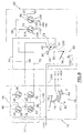
- the anti-theft device 10 according to the prior art shown schematically in the Figure 1 has a key 10, or a false key, which is intended to come into the barrel, or a false cannon, an anti-theft switch 12.
- the switch is designed to equip the dashboard of the vehicle and its design is of a substantially similar type that of the vehicle start switch according to the state of the art.
- the user operates the ignition key 10.
- the ignition key 10 is actually a false key in this that it does not necessarily act on a mechanical lock, although such an actual key associated with a lock provides a additional level of security by adding a means of additional locking or unlocking in chain with the general design of an electric lock.
- the anti-theft switch 10 includes a key 14 which is intended to detect the absence of key 10 or the presence in the introduced position of the latter.
- the switch 12 also includes a switch for multi-position control 16 for controlling the starting the vehicle engine and for controlling the supply of various electrical circuits of the vehicle such than in particular the engine ignition circuit.
- the key switch 14 is connected by a line 18 to a input of a central anti-theft device 20 while the command 16 is connected by line 22 to another input of the central anti-theft system 20, or equivalent operations of simulation.
- the anti-theft control unit 20 includes an analysis circuit which is particularly capable of reading the positions occupied by switches 14 and 16 of switch 12.
- the state-of-the-art anti-theft system comprises for example a microcontroller such as an INTEL 8051 circuit.
- This circuit contains a program for reading the input ports to inform the anti-theft system of the positions of the different switch switches 12.
- the central anti-theft device 20 can exchange signals with a station of interrogation and reception 24 which exchanges by lines 26 and 28 signals with, for example, an access badge 30 without key to the vehicle.
- the anti-theft control unit 20 activates an alarm system forgetting 38.
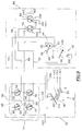
- the means for controlling the switching of the motorized electric anti-theft device are made according to a logic wired and protected without using a central burglar alarm according to the state of the art.
- the key switch 14 consists of two pairs 38 and 39 of mobile contact 40, 42 and 44, 46 which are all connected mechanically between them by a bond represented symbolically by the dotted line 48 so as to be move all four simultaneously between a first position illustrated in Figure 2 corresponding to the absence of key in the key switch 14 and a second position illustrated for example in Figure 3 corresponding to the presence a key in the key switch 14.
- the first movable contact 40 of the first pair 38 is permanently connected to a first polarity + BAT of the motor vehicle storage battery.
- the movable contact 40 is susceptible, in the absence of a key, to cooperate with a fixed contact 50 which is connected in permanence at the second movable contact 42 of the first pair 38.
- the fixed contact 50 and the movable contact 42 are connected between them by a line 52 and they are permanently connected by a line 54 to a first electrical supply terminal A1 of the motor 34 of the motorized anti-theft device.
- the second movable contact 42 of the first pair 38 cooperates with a fixed contact 56 which is permanently connected by a line 58 to a first fixed pad 60 of means 62 for detecting the state of the lock.
- the first movable contact 44 of the secondary pair 39 of movable contacts cooperates with a fixed contact 64.
- the first movable contact 44 is also connected at permanence at polarity + BAT of the power source in vehicle electrical energy.
- Fixed contact 64 is connected by line 66 to the second movable contact 46 of the second pair 39.
- the fixed contact 64 and the second movable contact 46 are also permanently connected by line 68 to the second terminal A2 for powering the motor 34.
- the second movable contact 46 of the second pair 39 cooperates with a fixed contact 70 which is permanently connected, by a line 72 to a second fixed stud 74 belonging to means 62 for detecting the state of the anti-theft device.
- the multi-position control switch 16 is a rotary type switch which includes a movable contact of command 76 which is permanently connected to the + BAT terminal of the vehicle battery.
- the movable control contact 76 is susceptible successively occupy several offset positions angularly with respect to each other and which are marked “O”, "ACC", "M”, and “D” in the figures.
- the rotary control movable contact 76 is likely to cooperate with one or more arranged conductive tracks in an arc forming the fixed contacts of the switch multi-position control 16.
- the introduction of a control key in the switch 12 or any action simulating such an introduction has the effect, initially, of causing a change of state of the key switch 14 then, under driver's action, to cause a change in position of the movable control contact 76 belonging to the multi-position control switch 16.
- the blocking module 86 comprises the motorized anti-theft device with its motor 34, the means 62 for detecting the locked state or unlocked from the anti-theft device and the inhibition device 82.
- the motor 34 is a reversal motor, by inversion of the supply polarities at its terminals supply A1 and A2.
- the output shaft of the motor 34 can thus rotate in one either direction between a locked position and a anti-theft unlocking position.
- a movable contact 88 which is linked in rotation with the shaft of motor output 34 and which is likely to come to cooperate with a mechanical locking stop 90 or with a mechanical unlocking stop 92.
- the means 62 for detecting the state of the anti-theft device are, in this first embodiment illustrated in FIGS. 2 to 7, constituted by a rotary switch comprising a contact mobile 94 which is permanently connected to the second polarity - BAT of the vehicle battery.
- the movable contact 94 is linked in rotation to the output shaft of the anti-theft motor 34, this mechanical connection being shown schematically by the dotted line 96.
- the movable contact 94 is capable of cooperating with the first fixed stud 60 produced in the form of a conductive track, with the first pad 60 and simultaneously with the second fixed stud 74 also produced in the form of a conductive track, or only with the second fixed stud 74.
- the ignition mobile 94 When the lock is in its locked state, the ignition mobile 94 only cooperates with the first fixed output pad 60 while it only cooperates with the second fixed stud 74 when the lock is in the unlocked position.
- the movable contact 94 cooperates simultaneously with the first 60 and 74 fixed pads of the rotary switch 62.
- each of lines 58 or 72 is connected to the -BAT polarity, or these two lines 58, 72 are connected simultaneously to this same polarity -BAT.
- the inhibition device 82 also consists of a rotary switch which has a movable contact 98 which is linked in rotation to the output shaft of the motor 34, the connection mechanical being shown schematically by a dotted line 100.
- the mobile muting contact 98 is likely to cooperate with a fixed stud 102 produced in the form of a conductive track, only when the lock is in position unlocked.
- the fixed pad 102 is connected to the electrical circuit + ALL vehicle ignition, the latter circuit being thus connected to the first polarity + BAT only when the anti-theft device is in position unlocked, this connection being ensured via the movable control contact 76, of conductive track 80, of movable muting contact 98 and fixed stud 102.
- the inhibiting device 82 is thus arranged downstream of the control switch to multiple positions 16.
- the first motor supply terminal A1 is electrically connected at polarity + BAT by line 54 and by the first contact mobile 40 of the first pair 38 of the key switch 14.
- the second motor supply terminal A2 is not connected to no polarity of the power source and the engine 34 is therefore stopped.
- line 68 connects terminal A2 on the one hand to the pad fixed 64 which is not connected to the polarity + BAT and, on the other hand, via the second mobile contact 46 of the second pair 39 with fixed stud 74 for detecting the unlocked state of the anti-theft device which is also not connected by the mobile contact 94 to the -BAT polarity of the vehicle battery.
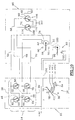
- the first terminal A1 of the motor 34 is connected to the -BAT polarity via the line 54, of the second movable contact 42 of the first pair 38, line 58, fixed pad 60 for detecting the locked state theft protection and via the mobile contact 94.
- the second terminal A2 of the motor 34 is connected to the polarity + BAT via line 68, line 66 and first movable contact 44 of the second pair 39.
- the motor supply terminals A1 and A2 34 are thus connected respectively to the polarities -BAT and + BAT and the engine begins to run counterclockwise while considering Figure 3, from its locked position to its anti-theft unlocking position.
- the user can rotate the movable control contact 76 to bring it into contact with the conductive track 78 and cause the supply of vehicle electrical accessories.
- the motor 34 is illustrated in an intermediate state, during rotation, between the position of lock from which it started and the unlock position that he will reach.
- the second motor supply terminal A2 34 remains connected to the + BAT polarity.
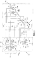
- the locking operation starting from the position illustrated in FIG. 5, consists in stopping the vehicle by returning the movable control contact 76 to its position O then by extracting the key, or by simulating this extraction out of the key switch.
- the four movable contacts 40, 42, 44 and 46 of the key switch 14 simultaneously changed state to find the state corresponding to the absence of key illustrated on the figure 6.
- This change of state immediately causes a power supply to the motor 34 in order to cause its rotation.
- the first terminal A1 of the motor 34 is connected to the polarity + BAT by line 54, line 52 and the first contact movable 40 of the first pair of contacts 38 of the switch key 14.
- the second terminal A2 for supplying the motor 34 is connected to -BAT polarity by line 62, the second contact mobile 46 of the second pair 39 of contacts, line 72, the second fixed pad 74 and the movable contact 94 of the switch rotary 62.
- motor 34 Due to the connection of motor terminals A1 and A2 34 at + BAT and -BAT polarities, respectively, motor 34 starts and turns clockwise considering the figure 6.
- This rotation is done to allow a change the lock status of its unlocked state illustrated in figure 6 towards its locked state illustrated in figure 2.
- the multi-position switch is of a slightly different design than that described previously insofar as the contact mobile 76 is connected to the polarity + BAT of the vehicle battery with interposition of the rotary muting switch 82.
- the movable control contact 76 is connected by a line 104 to the mobile muting contact 98.
- the conductive tracks 78, 80 and 84 are each directly connected to the electrical circuit vehicle correspondent.
- the means 62 for detecting the state of the lock are of a different conception from that of the rotary switch described with reference to Figures 2 to 7.
- the means 62 include an unlocking detection switch 106 of the anti-theft system and a lock detection switch 108 lock.
- the switch 106 has a movable contact 110 which is connected to the first fixed stud 60 and which, when the lock is not in the unlocked position, cooperates with a fixed contact 112 connected to the second polarity -BAT of the vehicle battery.
- the lock detection switch 108 includes a movable contact 114 which is connected to the second fixed stud of exit 74 and which, when the lock is not in its state locked illustrated in Figure 8, is likely to cooperate with a fixed contact 116 permanently connected to the polarity - BAT.
- the first terminal A1 for supplying the motor 34 is connected to the polarity + BAT of the vehicle battery while its second supply terminal A2 is not connected to the -BAT polarity because the movable contact 114 does not cooperate with the fixed contact 116.
- the engine 34 is therefore stopped.
- the movable control contact 76 is not not connected to polarity + BAT.
- the motor 34 is therefore powered and it begins its rotation counterclockwise considering figure 9.
- the switch lock detection 108 changed state and its contact mobile 114 cooperates with fixed contact 116.
- connection of the movable control contact 76 is always inhibited by the inhibitor 82 and the rotation of the motor 34 continues towards its position of unlocking.
- the mobile muting contact 98 is in contact with the fixed stud 102 and the movable contact 76 is connected to the polarity + BAT of the vehicle battery, allowing the connection of the various electrical circuits of the vehicle to this polarity as a function of the angular position occupied by the movable control contact 76 of the position switch order multiples 16.
- the first motor supply terminal A1 is then connected to the polarity + BAT of the vehicle battery while the second motor supply terminal A2 is connected to the polarity - BAT by the second movable contact 46 of the second pair 39 and by the movable contact 114 of the switch 108 for detecting the locking.
- the motor 34 is thus supplied and it starts to rotate clockwise, considering figure 12, to exit its unlocked position and return to its position lock shown in Figure 8.
- the device inhibition 82 immediately interrupts the electrical connection between the movable control contact 76 and the + BAT polarity.
- the start of this rotation also causes the immediate change of state of the detection switch unlocking 106.
Landscapes
- Engineering & Computer Science (AREA)
- Mechanical Engineering (AREA)
- Lock And Its Accessories (AREA)
- Ignition Installations For Internal Combustion Engines (AREA)
Abstract
L'antivol selon l'invention comporte des moyens (82) d'inhibition de l'alimentation en énergie électrique du circuit d'allumage du véhicule qui empêche le démarrage du moteur du véhicule tant que le moteur (34) d'entraînement d'un organe de blocage de l'antivol n'a pas atteint la position déverrouillée (92), les fonctions logiques de commande du verrouillage et du déverrouillage de l'antivol étant réalisées par une logique câblée et protégées de raccordement des bornes (A1, A2) d'alimentation du moteur électrique (34) de l'antivol motorisé aux polarités (+BAT, -BAT) de la batterie du véhicule. <IMAGE>The anti-theft device according to the invention comprises means (82) for inhibiting the supply of electrical energy to the ignition circuit of the vehicle which prevents the starting of the vehicle engine as long as the engine (34) for driving an anti-theft blocking member has not reached the unlocked position (92), the logic functions for controlling the locking and unlocking of the anti-theft device being carried out by a wired logic and protected from connection of the terminals (A1, A2 ) supplying the electric motor (34) of the motorized anti-theft device to the polarities (+ BAT, -BAT) of the vehicle battery. <IMAGE>
Description
La présente invention concerne un antivol électrique, notamment pour un véhicule automobile.The present invention relates to an electric anti-theft device, especially for a motor vehicle.
Il a déjà été proposé des dispositifs permettant de déverrouiller à distance et donc sans contact ni électrique, ni mécanique, les ouvrants d'un objet et notamment d'un véhicule automobile. En particulier, on a développé des techniques d'accès sans clef qui permettent d'accéder à des ressources sans avoir à sortir une clef mécanique, ou équivalente, d'autorisation de l'accès.Devices have already been proposed enabling unlock from a distance and therefore without electrical or contact mechanical, the opening of an object and in particular of a vehicle automobile. In particular, we developed techniques access without keys that allow access to resources without having to take out a mechanical key, or equivalent, access authorization.
Un tel système est très attractif par le confort qu'il apporte à l'usager et par les possibilités de gestion des accès par des moyens informatiques qu'il permet.Such a system is very attractive for the comfort it provides to the user and by the possibilities of access management by IT resources it allows.
Dans l'application au verrouillage et au déverrouillage d'ouvrants, comme ceux d'un véhicule automobile, ou d'un antivol de sécurité comme celui d'une colonne de direction, ou de l'arbre de sortie de la boíte de vitesses d'un véhicule, on a dans cette optique proposé des systèmes mécaniques utilisant des organes moteurs de type électrique tels qu'un moteur électrique tournant ou un électroaimant.In the application for locking and unlocking openings, such as those of a motor vehicle, or a security lock such as that of a steering column, or of the output shaft of the gearbox of a vehicle, we have in this perspective proposed mechanical systems using electric type drive members such as an engine electric rotating or an electromagnet.
Quand le système de gestion des accès reconnaít le droit d'accès et une demande d'accès, un organe de commande produit un ordre actionnement qui excite l'organe moteur électrique. L'antivol et/ou le verrou change d'état en passant de l'état verrouillé à l'état déverrouillé.When the access management system recognizes the right and an access request, a control unit produces an actuation command which excites the motor member electric. The lock and / or the lock changes state while passing from the locked state to the unlocked state.
Une séquence analogue inverse se produit pour la sortie et/ou l'activation de l'antivol.Reverse analog sequence occurs for output and / or activation of the anti-theft device.
Selon une conception connue, décrite et représentée dans la demande de brevet français n° 93 11671 du 30/O9/1993, il a déjà été proposé un procédé de contrôle d'un antivol de véhicule automobile, notamment avec système d'accès par commande à distance, faisant notamment appel à un commutateur de commande de démarrage et d'alimentation électrique des accessoires du véhicule et du circuit d'allumage du moteur du véhicule.According to a known concept, described and represented in French patent application No. 93 11671 of 30/09/1993, it has a method of controlling an anti-theft device has already been proposed motor vehicle, in particular with access system by remote control, in particular using a start and power control switch vehicle accessories and ignition system of the vehicle engine.
Selon le procédé, dans une phase de désactivation de l'antivol, on accède au véhicule, par exemple avec une télécommande, on manoeuvre un commutateur qui reproduit en la simulant la manipulation des clefs mécaniques habituelles, on détecte une position déterminée du commutateur pour produire une interrogation d'identification de la demande de déverrouillage de l'antivol, on produit en réponse un ordre d'activation de positions successives du commutateur et un ordre de déverrouillage de l'antivol.According to the method, in a phase of deactivation of the lock, the vehicle is accessed, for example with a remote control, we operate a switch which reproduces in simulating the manipulation of the usual mechanical keys, a determined position of the switch is detected for produce a request identification query unlocking of the anti-theft device, an order is produced in response activation of successive switch positions and a anti-theft unlocking order.
Dans une phase d'activation de l'antivol, on détecte une manoeuvre d'activation de l'antivol sur le commutateur, cette manoeuvre reproduisant les manipulations habituelles des clefs mécaniques, on active l'antivol, on désactive les positions successives du commutateur.In an anti-theft activation phase, a anti-theft activation operation on the switch, this maneuver reproducing the usual manipulations of mechanical keys, we activate the lock, we deactivate them successive switch positions.
Pour la mise en place d'un tel procédé, il est fait appel à un antivol du type comportant :
- un commutateur d'antivol pour la commande du démarrage du moteur du véhicule et de l'alimentation de différents circuits électriques du véhicule ;
- un antivol motorisé comportant un moteur électrique d'entraínement d'un organe de blocage entre une position verrouillée et une position déverrouillée, par inversion des polarités des bornes d'alimentation du moteur, par exemple à travers un bloc d'alimentation électrique du moteur ;
- et du type dans lequel le commutateur d'antivol comporte
- - un interrupteur de clef pour détecter la simulation de l'introduction d'une clef dans le commutateur d'antivol ;
- - et un interrupteur de commande à positions multiples pour commander en séquence l'alimentation de plusieurs circuits électriques du véhicule et du démarreur, comportant un contact mobile de commande relié à une polarité d'une source d'alimentation électrique, et une série de contacts fixes, avec lesquels le contact mobile de commande entre successivement en contact lors de la manoeuvre du commutateur en vue de provoquer le démarrage du véhicule.
- an anti-theft switch for controlling the starting of the vehicle engine and the supply of various electrical circuits of the vehicle;
- a motorized anti-theft device comprising an electric motor driving a blocking member between a locked position and an unlocked position, by reversing the polarities of the motor supply terminals, for example through an electric motor supply unit;
- and the type in which the anti-theft switch includes
- - a key switch to detect the simulation of the introduction of a key into the anti-theft switch;
- - and a multi-position control switch for sequentially controlling the supply of several electrical circuits of the vehicle and the starter, comprising a movable control contact connected to a polarity of an electrical power source, and a series of contacts fixed, with which the movable control contact successively comes into contact when the switch is operated in order to cause the vehicle to start.
Dans la conception décrite et représentée dans ce document, l'antivol comporte également une centrale d'antivol connectée aux éléments précédents pour mettre en oeuvre un procédé de contrôle de l'antivol. La centrale d'antivol comporte notamment un microprocesseur qui assure la gestion du procédé de contrôle de l'antivol.In the design described and shown in this document, the anti-theft system also includes a central anti-theft system connected to the previous elements to implement a anti-theft control method. The anti-theft system includes including a microprocessor which manages the anti-theft control method.
La présente invention a pour but de proposer une nouvelle conception d'un antivol électrique du type mentionné précédemment, qui assure toutes les fonctions souhaitées, avec la fiabilité requise, mais sans qu'il soit nécessaire de faire appel à une centrale d'antivol réalisée sous la forme d'un microprocesseur, c'est-à-dire une conception dans laquelle la logique de commande du verrouillage et du déverrouillage de l'antivol est réalisée sous la forme d'une logique câblée et protégée.The object of the present invention is to propose a new design of an electric lock of the type mentioned previously, which provides all the desired functions, with the required reliability, but without the need to use a central anti-theft system in the form of a microprocessor, i.e. a design in which the control logic for locking and unlocking the anti-theft device is made in the form of wired logic and protected.
Dans ce but, l'invention propose un antivol électrique du type mentionné précédemment, caractérisé en ce que le moteur électrique de l'antivol motorisé comporte :
- une première borne d'alimentation qui est reliée à une première polarité de la source d'alimentation à travers l'interrupteur de clef et en l'absence de clef, ou qui est reliée à la seconde polarité de la source d'alimentation à travers l'interrupteur de clef, en présence de clef, et à travers des moyens de détection de l'état de l'antivol, lorsque l'antivol n'est pas en position déverrouillée ;
- et une seconde borne d'alimentation qui est reliée à la première polarité de la source d'alimentation à travers l'interrupteur de clef et en présence de clef, ou qui est reliée à la seconde polarité de la source d'alimentation à travers l'interrupteur de clef, en l'absence de clef, et à travers lesdits moyens de détection de l'état de l'antivol, lorsque l'antivol n'est pas en position verrouillée.
- a first power supply terminal which is connected to a first polarity of the power source through the key switch and in the absence of a key, or which is connected to the second polarity of the power source through the key switch, in the presence of a key, and through means for detecting the state of the anti-theft device, when the anti-theft device is not in the unlocked position;
- and a second power supply terminal which is connected to the first polarity of the power source through the key switch and in the presence of a key, or which is connected to the second polarity of the power source through the key switch, in the absence of a key, and through said means for detecting the state of the anti-theft device, when the anti-theft device is not in the locked position.
Selon d'autres caractéristiques de l'invention :
- l'interrupteur de clef comporte deux paires de contacts mobiles montés mobiles simultanément entre une première position correspondant à l'absence de clef et une seconde position correspondant à la présence de clef, parmi lesquelles
- une première paire de contacts mobiles dont un premier contact mobile est relié à la première polarité de la source d'alimentation et est susceptible de coopérer, en l'absence de clef, avec un contact fixe relié en permanence à la première borne d'alimentation du moteur et au second contact mobile de cette première paire qui, en présence de clef, est susceptible de coopérer avec un premier plot de sortie des moyens de détection de l'état de l'antivol qui est relié à la seconde polarité de la source d'alimentation lorsque l'antivol n'est pas en position déverrouillée ;
- et une seconde paire de contacts mobiles dont un premier contact mobile est relié à la première polarité de la source d'alimentation et susceptible de coopérer, en présence de clef, avec un contact fixe relié en permanence à la seconde borne d'alimentation et au contact mobile de cette seconde paire qui, en l'absence de clef, est susceptible de coopérer avec un second plot de sortie des moyens de détection de l'état de l'antivol qui est relié à la seconde polarité de la source d'alimentation lorsque l'antivol n'est pas en position verrouillée ;
- les moyens de détection de l'antivol comportent un contact mobile relié à la seconde polarité de la source d'alimentation et qui est susceptible de coopérer avec le premier plot fixe de sortie lorsque l'antivol n'est pas en position déverrouillée, et de coopérer avec le second plot fixe de sortie lorsque l'antivol n'est pas en position verrouillée ;
- les premiers et seconds plots de sortie sont des pistes conductrices adjacentes et le contact mobile des moyens de détection de l'état de l'antivol est lié en rotation à l'arbre de sortie du moteur de l'antivol ;
- les moyens de détection de l'état de l'antivol comportent
- - un interrupteur de détection du déverrouillage de l'antivol qui comporte un contact mobile relié audit premier plot de sortie et qui est susceptible de coopérer avec un contact fixe reliée à la seconde polarité de la source d'alimentation lorsque l'antivol n'est pas en position déverrouillée ;
- - et un interrupteur de détection du verrouillage de l'antivol qui comporte un contact mobile relié audit second plot de sortie et qui est susceptible de coopérer avec un contact fixe relié à la seconde polarité de la source d'alimentation lorsque l'antivol n'est pas en position verrouillée ;
- - l'un au moins des contacts fixes de l'interrupteur de commande à positions multiples du commutateur d'antivol est relié au circuit électrique associé du véhicule par une disposition d'inhibition qui n'établit l'alimentation électrique de ce circuit que lorsque l'antivol est en position déverrouillée ;
- - le dispositif d'inhibition est un interrupteur d'inhibition dont le contact mobile est relié audit contact fixe de l'interrupteur de commande et coopère avec un plot fixe relié audit circuit électrique lorsque l'antivol est en position déverrouillée ;
- - le contact mobile de commande l'interrupteur de commande à positions multiples du commutateur d'antivol est relié à une polarité de la source d'alimentation par un dispositif d'inhibition qui n'établit la liaison électrique que lorsque l'antivol est en position déverrouillée ;
- - le dispositif d'inhibition est un interrupteur d'inhibition dont le contact mobile est relié à une polarité de la source d'alimentation et coopère avec un plot fixe relié au contact mobile de commande lorsque l'antivol est en position déverrouillée ;
- - le contact mobile de l'interrupteur d'inhibition est lié en rotation au moteur de l'antivol motorisé ;
- - le commutateur d'antivol est un commutateur rotatif.
- the key switch comprises two pairs of movable contacts mounted movable simultaneously between a first position corresponding to the absence of a key and a second position corresponding to the presence of a key, among which
- a first pair of mobile contacts, a first mobile contact of which is connected to the first polarity of the power source and is capable of cooperating, in the absence of a key, with a fixed contact permanently connected to the first power supply terminal of the motor and to the second movable contact of this first pair which, in the presence of a key, is capable of cooperating with a first output pad of the means for detecting the state of the anti-theft device which is connected to the second polarity of the source power when the lock is not in the unlocked position;
- and a second pair of movable contacts of which a first movable contact is connected to the first polarity of the power source and capable of cooperating, in the presence of a key, with a fixed contact permanently connected to the second power supply terminal and to the movable contact of this second pair which, in the absence of a key, is capable of cooperating with a second output pad of the means for detecting the state of the lock which is connected to the second polarity of the power source when the lock is not in the locked position;
- the anti-theft detection means comprise a movable contact connected to the second polarity of the power source and which is capable of cooperating with the first fixed output pad when the anti-theft device is not in the unlocked position, and cooperate with the second fixed output pad when the lock is not in the locked position;
- the first and second output pads are adjacent conductive tracks and the movable contact of the anti-theft state detection means is linked in rotation to the output shaft of the anti-theft motor;
- the anti-theft state detection means include
- - an anti-theft unlocking detection switch which comprises a movable contact connected to said first output pad and which is capable of cooperating with a fixed contact connected to the second polarity of the power source when the anti-theft device is not not in the unlocked position;
- - And an anti-theft locking detection switch which comprises a movable contact connected to said second output pad and which is capable of cooperating with a fixed contact connected to the second polarity of the power source when the anti-theft device does not is not in the locked position;
- - at least one of the fixed contacts of the multi-position control switch of the anti-theft switch is connected to the associated electrical circuit of the vehicle by an inhibition arrangement which establishes the electrical supply of this circuit only when the lock is in the unlocked position;
- - the inhibition device is an inhibition switch whose movable contact is connected to said fixed contact of the control switch and cooperates with a fixed stud connected to said electrical circuit when the anti-theft device is in the unlocked position;
- - the mobile control contact the multi-position control switch of the anti-theft switch is connected to a polarity of the power source by an inhibition device which establishes the electrical connection only when the anti-theft device is in unlocked position;
- - the inhibition device is an inhibition switch whose movable contact is connected to a polarity of the power source and cooperates with a fixed stud connected to the movable control contact when the anti-theft device is in the unlocked position;
- - the movable contact of the muting switch is linked in rotation to the motor of the motorized anti-theft device;
- - the anti-theft switch is a rotary switch.
D'autres caractéristiques et avantages de l'invention apparaítront à la lecture de la description détaillée qui va suivre pour la compréhension de laquelle on se reportera aux dessins annexés dans lesquels :
- La figure 1 est un schéma illustrant un principe de réalisation d'un antivol selon l'état de la technique comportant notamment une centrale électronique d'antivol;
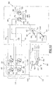
- la figure 2 est un schéma qui illustre un premier mode de réalisation d'un antivol selon l'invention sur lequel l'antivol électrique est représenté à l'état verrouillé ;
- la figure 3 est un schéma similaire à celui de la figure 2 sur lequel l'antivol électrique est à l'état verrouillé mais après la simulation de l'introduction d'une clef ;
- la figure 4 est un schéma similaire à celui de la figure 3 sur lequel l'antivol électrique passe de l'état verrouillé à l'état déverrouillé ;
- la figure 5 est un schéma similaire à celui de la figure 4 sur lequel l'antivol électrique est représenté à l'état déverrouillé ;
- la figure 6 est un schéma similaire à celui de la figure 5 sur lequel l'antivol électrique est représenté à l'état déverrouillé après simulation du retrait d'une clef ;
- la figure 7 est un schéma similaire à celui de la figure 6 sur lequel l'antivol passe de l'état déverrouillé à l'état verrouillé ; et
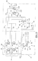
- les figures 8 à 13 sont des schémas similaires à ceux des figures 2 à 7 qui illustrent un second mode de réalisation d'un antivol conforme aux enseignements de l'invention.
- FIG. 1 is a diagram illustrating a principle for producing an anti-theft device according to the state of the art comprising in particular an electronic anti-theft control unit;
- FIG. 2 is a diagram which illustrates a first embodiment of an anti-theft device according to the invention in which the electric anti-theft device is shown in the locked state;
- Figure 3 is a diagram similar to that of Figure 2 in which the electric lock is in the locked state but after the simulation of the introduction of a key;
- Figure 4 is a diagram similar to that of Figure 3 in which the electric lock changes from the locked state to the unlocked state;
- Figure 5 is a diagram similar to that of Figure 4 in which the electric lock is shown in the unlocked state;
- Figure 6 is a diagram similar to that of Figure 5 in which the electric lock is shown in the unlocked state after simulating the removal of a key;
- Figure 7 is a diagram similar to that of Figure 6 in which the lock changes from the unlocked state to the locked state; and
- Figures 8 to 13 are diagrams similar to those of Figures 2 to 7 which illustrate a second embodiment of an anti-theft device according to the teachings of the invention.
L'antivol 10 selon l'état de la technique schématisé à la
figure 1 comporte une clef 10, ou une fausse clef, qui est
destinée à venir s'introduire dans le canon, ou un faux canon,
d'un commutateur d'antivol 12.The
Le commutateur est prévu pour équiper le tableau de bord du véhicule et sa conception est de type sensiblement proche de celle du commutateur de démarrage d'un véhicule selon l'état de la technique.The switch is designed to equip the dashboard of the vehicle and its design is of a substantially similar type that of the vehicle start switch according to the state of the art.
L'utilisateur manoeuvre la clef de contact 10.The user operates the
La clef de contact 10 est en fait une fausse clef en ce
qu'elle n'agit pas nécessairement sur une serrure mécanique,
bien qu'une telle clef réelle associée à une serrure apporte un
degré supplémentaire de sécurité en ajoutant un moyen de
verrouillage ou de déverrouillage supplémentaire en chaíne
avec la conception générale d'un antivol électrique.The
Le commutateur d'antivol 10 comporte un interrupteur de
clef 14 qui est destiné à détecter l'absence de la clef 10 ou la
présence en position introduite de cette dernière.The
Le commutateur 12 comporte également un interrupteur de
commande à positions multiples 16 pour la commande du
démarrage du moteur du véhicule et pour la commande de
l'alimentation de différents circuits électriques du véhicule tels
que notamment le circuit d'allumage du moteur.The
L'interrupteur de clef 14 est relié par une ligne 18 à une
entrée d'une centrale d'antivol 20 tandis que l'interrupteur de
commande 16 est relié par une ligne 22 à une autre entrée de
la centrale d'antivol 20, ou des opérations équivalentes de
simulation.The
La centrale d'antivol 20 comporte un circuit d'analyse qui
est notamment capable de lire les positions qu'occupent les
interrupteurs 14 et 16 du commutateur 12.The
La centrale d'antivol selon l'état de la technique comporte
par exemple un microcontrôleur tel qu'un circuit INTEL 8051.
Ce circuit contient un programme de lecture des ports d'entrée
pour informer la centrale d'antivol des positions des différents
interrupteurs du commutateur 12. Selon une conception
connue, et par une autre entrée et une ligne 23, la centrale
d'antivol 20 peut échanger des signaux avec une station
d'interrogation et de réception 24 qui échange par des lignes
26 et 28 des signaux avec, par exemple, un badge 30 d'accès
sans clef au véhicule.The state-of-the-art anti-theft system comprises
for example a microcontroller such as an INTEL 8051 circuit.
This circuit contains a program for reading the input ports
to inform the anti-theft system of the positions of the different
switch switches 12. According to a design
known, and by another entrance and a
En fonction des échanges avec la centrale d'antivol 20,
celle-ci produit sur une liaison 32 un signal de commande de la
mise en marche, dans l'un ou l'autre sens, d'un moteur
d'antivol 34 qui appuie sur un organe 36 de blocage
mécanique de la colonne de direction du véhicule, ou de
l'arbre de sortie de la boíte de vitesses.Depending on the exchanges with the central
Par ailleurs, si l'utilisateur oublie le badge radiofréquence
30 à l'intérieur du véhicule, ou s'il omet de manoeuvrer la clef
10 pour mettre en oeuvre une séquence d'activation de
l'antivol alors qu'il laisse son badge dans le véhicule, la
centrale d'antivol 20 produit l'activation d'un moyen d'alarme
d'oubli 38.Furthermore, if the user forgets the
On décrira maintenant un premier mode de réalisation d'un antivol électrique selon l'invention en se reportant au schéma de la figure 2 sur laquelle des composants identiques ou similaires à ceux de la figure 1 sont désignés par les mêmes chiffres de référence.We will now describe a first embodiment an electric lock according to the invention with reference to diagram of Figure 2 in which identical components or similar to those in Figure 1 are designated by same reference figures.
Conformément au principe de l'antivol électrique selon l'invention, les moyens de commande de la commutation de l'antivol électrique motorisé sont réalisés selon une logique câblée et protégée sans faire appel à une centrale d'antivol selon l'état de la technique.In accordance with the principle of electric anti-theft according to the invention, the means for controlling the switching of the motorized electric anti-theft device are made according to a logic wired and protected without using a central burglar alarm according to the state of the art.
L'interrupteur de clef 14 est constitué par deux paires 38
et 39 de contact mobile 40, 42 et 44, 46 qui sont tous reliés
mécaniquement entre eux par une liaison représentée
symboliquement par la ligne en pointillés 48 de manière à se
déplacer tous les quatre simultanément entre une première
position illustrée à la figure 2 correspondant à l'absence de
clef dans l'interrupteur de clef 14 et une seconde position
illustrée par exemple à la figure 3 correspondant à la présence
d'une clef dans l'interrupteur de clef 14.The
Le premier contact mobile 40 de la première paire 38 est
relié en permanence à une première polarité +BAT de la
batterie d'accumulateur du véhicule automobile.The first
Le contact mobile 40 est susceptible, en l'absence de clef,
de coopérer avec un contact fixe 50 qui est relié en
permanence au second contact mobile 42 de la première paire
38.The
Le contact fixe 50 et le contact mobile 42 sont reliés entre
eux par une ligne 52 et ils sont reliés en permanence par une
ligne 54 à une première borne A1 d'alimentation électrique du
moteur 34 de l'antivol motorisé. The fixed
En présence d'une clef dans l'interrupteur de clef 14, et
comme cela est notamment illustré à la figure 3, le second
contact mobile 42 de la première paire 38 coopère avec un
contact fixe 56 qui est relié en permanence, par une ligne 58 à
un premier plot fixe 60 de moyens 62 de détection de l'état de
l'antivol.In the presence of a key in the
En présence d'une clef, et comme cela est illustré
notamment sur la figure 3, le premier contact mobile 44 de la
secondaire paire 39 de contacts mobiles, coopère avec un
contact fixe 64.In the presence of a key, and as illustrated
in particular in FIG. 3, the first
Le premier contact mobile 44 est également relié en
permanence à la polarité +BAT de la source d'alimentation en
énergie électrique du véhicule.The first
Le contact fixe 64 est relié par une ligne 66 au second
contact mobile 46 de la seconde paire 39.Fixed
Le contact fixe 64 et le second contact mobile 46 sont
également reliés en permanence, par une ligne 68 à la
seconde borne A2 d'alimentation électrique du moteur 34.The fixed
En l'absence de clef, et comme on peut le voir sur la
figure 2, le second contact mobile 46 de la seconde paire 39
coopère avec un contact fixe 70 qui est relié en permanence,
par une ligne 72 à un second plot fixe 74 appartenant aux
moyens 62 de détection de l'état de l'antivol.In the absence of a key, and as we can see on the
Figure 2, the second
Dans le mode de réalisation illustré sur les figures,
l'interrupteur de commande à positions multiples 16 est un
interrupteur du type rotatif qui comporte un contact mobile de
commande 76 qui est relié en permanence à la borne +BAT de
la batterie du véhicule.In the embodiment illustrated in the figures,
the
Le contact mobile de commande 76 est susceptible
d'occuper successivement plusieurs positions décalées
angulairement les unes par rapport aux autres et qui sont
repérées "O", "ACC", "M", et "D" sur les figures. The
Dans ces positions successives d'arrêt, d'alimentation
d'accessoires électriques, de marche, et de démarrage, le
contact mobile rotatif de commande 76 est susceptible de
coopérer avec une ou plusieurs pistes conductrices agencées
en arc de cercle constituant les contacts fixes de l'interrupteur
de commande à positions multiples 16.In these successive stop, feed positions
electrical, walking, and starting accessories, the
rotary control
Lorsque le contact mobile 76 est dans sa position d'arrêt
illustrée sur la figure 2, position O, il ne coopère avec aucun
contact fixe.When the
Lorsque le contact mobile de commande 76 est dans la
position "ACC", il coopère avec une piste fixe 78 qui est reliée
électriquement au circuit +ACC d'alimentation des accessoires
du véhicule.When the
Lorsque l'organe mobile de commande 76 est dans la
position de marche "M", il est simultanément en contact avec
la piste 78 et avec une piste conductrice 80 qui est reliée au
circuit +ALL d'allumage du moteur du véhicule à travers un
dispositif d'inhibition 82.When the
Lorsque le contact mobile de commande 76 est dans la
position "D", il est en contact simultanément avec la piste 80
et avec une piste conductrice 84 qui est reliée au circuit +DEM
d'alimentation électrique du démarreur qui équipe le moteur à
combustion du véhicule.When the
L'introduction d'une clef de commande dans le
commutateur 12 ou toute action simulant une telle introduction
de clef a pour effet, dans un premier temps, de provoquer un
changement d'état de l'interrupteur de clef 14 puis, sous
l'action du conducteur, de provoquer un changement de
position du contact mobile de commande 76 appartenant à
l'interrupteur de commande à positions multiples 16. The introduction of a control key in the
On décrira maintenant plus en détail le module de blocage 86 entouré par une ligne en traits pointillés à la partie droite de la figure 2.The blocking module will now be described in more detail. 86 surrounded by a dotted line on the right in Figure 2.
Le module de blocage 86 comporte l'antivol motorisé avec
son moteur 34, les moyens 62 de détection de l'état verrouillé
ou déverrouillé de l'antivol et le dispositif d'inhibition 82.The blocking
Le moteur 34 est un moteur à inversion de sens, par
inversion des polarités d'alimentation à ses bornes
d'alimentation A1 et A2.The
L'arbre de sortie du moteur 34 peut ainsi tourner dans l'un
ou l'autre sens entre une position de verrouillage et une
position de déverrouillage de l'antivol.The output shaft of the
On a représenté de manière schématique sur la figure 2
un contact mobile 88 qui est lié en rotation avec l'arbre de
sortie du moteur 34 et qui est susceptible de venir coopérer
avec une butée mécanique de verrouillage 90 ou avec une
butée mécanique de déverrouillage 92.There is shown schematically in Figure 2
a
Les moyens 62 de détection de l'état de l'antivol sont, dans ce premier mode de réalisation illustré aux figures 2 à 7, constitués par un commutateur rotatif comportant un contact mobile 94 qui est relié en permanence à la seconde polarité - BAT de la batterie du véhicule.The means 62 for detecting the state of the anti-theft device are, in this first embodiment illustrated in FIGS. 2 to 7, constituted by a rotary switch comprising a contact mobile 94 which is permanently connected to the second polarity - BAT of the vehicle battery.
Le contact mobile 94 est lié en rotation à l'arbre de sortie
du moteur 34 de l'antivol, cette liaison mécanique étant
schématisée par la ligne en pointillés 96.The
Selon sa position angulaire, le contact mobile 94 est
susceptible de coopérer avec le premier plot fixe 60 réalisé
sous la forme d'une piste conductrice, avec le premier plot 60
et simultanément avec le second plot fixe 74 également réalisé
sous la forme d'une piste conductrice, ou seulement avec le
second plot fixe 74. Depending on its angular position, the
Lorsque l'antivol est dans son état verrouillé, le contact
mobile 94 ne coopère qu'avec le premier plot fixe de sortie 60
tandis qu'il coopère seulement avec le second plot fixe 74
lorsque l'antivol est en position déverrouillée.When the lock is in its locked state, the ignition
mobile 94 only cooperates with the first
Pour un état intermédiaire de l'antivol, correspondant à
une transition, dans l'un ou l'autre sens, entre l'état verrouillé
et l'état déverrouillé, le contact mobile 94 coopère
simultanément avec les premiers 60 et 74 plots fixes du
commutateur rotatif 62.For an intermediate state of the lock, corresponding to
a transition, in either direction, between the locked state
and the state unlocked, the
En fonction de la position angulaire du contact mobile 94,
chacune des lignes 58 ou 72 est reliée à la polarité -BAT, ou
ces deux lignes 58, 72 sont reliées simultanément à cette
même polarité -BAT.Depending on the angular position of the
Le dispositif d'inhibition 82 est également constitué par un
commutateur rotatif qui comporte un contact mobile 98 qui est
lié en rotation à l'arbre de sortie du moteur 34, la liaison
mécanique étant schématisée par une ligne en pointillés 100.The
Le contact mobile d'inhibition 98 est susceptible de
coopérer avec un plot fixe 102 réalisé sous la forme d'une
piste conductrice, uniquement lorsque l'antivol est en position
déverrouillée.The
Le plot fixe 102 est relié au circuit électrique +ALL
d'allumage du véhicule, ce dernier circuit n'étant ainsi relié à
la première polarité +BAT que lorsque l'antivol est en position
déverrouillée, cette liaison étant assurée par l'intermédiaire du
contact mobile de commande 76, de la piste conductrice 80, du
contact mobile d'inhibition 98 et du plot fixe 102.The fixed
Du point de vue fonctionnel, le dispositif d'inhibition 82 est
ainsi disposé en aval de l'interrupteur de commande à
positions multiples 16.From a functional point of view, the inhibiting
On décrira maintenant le mode de fonctionnement de l'antivol électrique illustré aux figures 2 à 7. We will now describe the operating mode of the electric lock shown in Figures 2 to 7.
Dans la position verrouillée illustrée sur la figure 2, et en
l'absence de clef dans l'interrupteur de clef 14, la première
borne A1 d'alimentation du moteur 34 est reliée électriquement
à la polarité +BAT par la ligne 54 et par le premier contact
mobile 40 de la première paire 38 de l'interrupteur de clef 14.In the locked position illustrated in Figure 2, and in
the absence of a key in the
La seconde borne A2 d'alimentation du moteur 34 n'est
reliée à aucune polarité de la source d'alimentation et le
moteur 34 est donc à l'arrêt.The second motor supply terminal A2 is not
connected to no polarity of the power source and the
En effet, la ligne 68 relie la borne A2 d'une part au plot
fixe 64 qui n'est pas relié à la polarité +BAT et, d'autre part,
par l'intermédiaire du second contact mobile 46 de la seconde
paire 39 au plot fixe 74 de détection de l'état déverrouillé de
l'antivol qui lui non plus n'est pas relié par le contact mobile 94
à la polarité -BAT de la batterie du véhicule.Indeed,
Sur la figure 3, le conducteur a provoqué, ou simulé,
l'introduction d'une clef dans l'interrupteur de clef 14
provoquant immédiatement le changement d'état simultané des
quatre contacts mobiles 40, 42, 44 et 46 de l'interrupteur de
clef 14.In Figure 3, the driver caused, or simulated,
the introduction of a key into the
Du fait de ce changement d'état, la première borne A1 du
moteur 34 est reliée à la polarité -BAT par l'intermédiaire de la
ligne 54, du second contact mobile 42 de la première paire 38,
de la ligne 58, du plot fixe 60 de détection de l'état verrouillé
de l'antivol et par l'intermédiaire du contact mobile 94.Due to this change of state, the first terminal A1 of the
La seconde borne A2 du moteur 34 est reliée à la polarité
+BAT par l'intermédiaire de la ligne 68, de la ligne 66 et du
premier contact mobile 44 de la seconde paire 39.The second terminal A2 of the
Les bornes A1 et A2 d'alimentation du moteur 34 sont
ainsi reliées respectivement aux polarités -BAT et +BAT et le
moteur commence à tourner, dans le sens anti-horaire en
considérant la figure 3, de sa position de verrouillage vers sa
position de déverrouillage de l'antivol. The motor supply terminals A1 and
Simultanément, l'utilisateur peut provoquer la rotation du
contact mobile de commande 76 pour l'amener en contact avec
la piste conductrice 78 et provoquer l'alimentation des
accessoires électriques du véhicule.At the same time, the user can rotate the
Si l'utilisateur continue d'entraíner en rotation le contact
mobile 76, et qu'il l'amène en contact avec la piste 80, il ne se
produit aucune alimentation du circuit d'allumage +ALL car le
contact mobile d'inhibition 98 est dans sa position de repos
dans laquelle il interrompt l'alimentation du circuit +ALL.If the user continues to rotate the contact
mobile 76, and that it brings it into contact with
En considérant la figure 4, le moteur 34 est illustré dans
un état intermédiaire, en cours de rotation, entre la position de
verrouillage dont il est parti et la position de déverrouillage
qu'il va atteindre.Considering FIG. 4, the
Dans cette position intermédiaire, on constate que le
contact mobile 94 du commutateur rotatif 62 est simultanément
en contact avec les deux plot fixe de sortie 60 et 74.In this intermediate position, we see that the
moving
Tandis que le contact mobile d'inhibition 98 est dans une
position intermédiaire dans laquelle il n'est pas encore en
contact avec le plot fixe 102 et dans laquelle l'alimentation
électrique du circuit d'allumage +ALL n'est toujours pas
établie.While the muting
La rotation du moteur 34, dans le sens anti-horaire en
considérant la figure 4, se poursuit jusqu'à ce qu'il atteigne la
position de déverrouillage illustrée sur la figure 5 dans laquelle
son organe mobile 88 est en butée contre la butée mécanique
de déverrouillage 92.The rotation of the
Dans cette position angulaire arrêtée de l'arbre de sortie
du moteur 34, le contact mobile 94 du commutateur rotatif 62
est arrêté dans sa position angulaire extrême opposée à celle
qu'il occupait à la figure 2 et il n'est plus en contact qu'avec le
second plot fixe de sortie 74. In this fixed angular position of the
Dans cet état déverrouillé, on constate que la première
borne A1 d'alimentation du moteur 34 n'est plus reliée à la
polarité -BAT car le contact mobile 94 n'est plus en contact
avec le premier plot fixe de sortie 60.In this unlocked state, we see that the first
motor supply terminal A1 is no longer connected to the
-BAT polarity because the
La seconde borne A2 d'alimentation du moteur 34
demeure quant à elle reliée à la polarité +BAT.The second motor
Ainsi, dès que le moteur 34 atteint sa position de
déverrouillage, son alimentation électrique est interrompue et
il s'arrête.Thus, as soon as the
Dans cette position de déverrouillage, on constate que le
contact mobile d'inhibition 98 est en contact avec le plot fixe
102 et que le circuit +ALL d'allumage du moteur est relié à la
piste conductrice 80 de l'interrupteur de commande à positions
multiples 16.In this unlocking position, it can be seen that the
Ainsi, si l'utilisateur amène le contact mobile de
commande 76 dans la position M, il alimente le circuit
d'allumage +ALL et si il l'amène dans la position D, il alimente
simultanément le circuit d'allumage +ALL et le circuit
d'alimentation électrique +DEM du démarreur du véhicule
pouvant ainsi provoquer le démarrage du moteur à combustion
du véhicule tout en ayant la certitude que l'antivol du véhicule
a préalablement été déverrouillé.Thus, if the user brings the mobile contact of
Après avoir fait démarrer le moteur, le contact mobile de
commande 76 reste dans la position M correspondant à la
marche du moteur.After starting the engine, the movable contact of
On décrira maintenant le fonctionnement de l'antivol, en référence aux figures 6 et 7, lorsque le conducteur quitte le véhicule après l'avoir arrêté.We will now describe the operation of the anti-theft device, in reference to Figures 6 and 7, when the driver leaves the vehicle after stopping it.
L'opération de verrouillage, en partant de la position
illustrée sur la figure 5, consiste à arrêter le véhicule en
ramenant le contact mobile de commande 76 dans sa position
O puis en extrayant la clef, ou en simulant cette extraction
hors de l'interrupteur de clef.The locking operation, starting from the position
illustrated in FIG. 5, consists in stopping the vehicle by
returning the
Après le retrait de la clef, et comme cela est illustré sur la
figure 6, les quatre contacts mobiles 40, 42, 44 et 46 de
l'interrupteur de clef 14 ont changé simultanément d'état pour
retrouver l'état correspondant à l'absence de clef illustré sur la
figure 6.After removing the key, and as illustrated on the
Figure 6, the four
Ce changement d'état provoque immédiatement une
alimentation électrique du moteur 34 en vue de provoquer sa
rotation.This change of state immediately causes a
power supply to the
En effet, la première borne A1 du moteur 34 est reliée à la
polarité +BAT par la ligne 54, la ligne 52 et le premier contact
mobile 40 de la première paire de contacts 38 de l'interrupteur
de clef 14.Indeed, the first terminal A1 of the
La seconde borne A2 d'alimentation du moteur 34 est
reliée à la polarité -BAT par la ligne 62, le second contact
mobile 46 de la seconde paire 39 de contacts, la ligne 72, le
second plot fixe 74 et le contact mobile 94 du commutateur
rotatif 62.The second terminal A2 for supplying the
Du fait du raccordement des bornes A1 et A2 du moteur
34 aux polarités +BAT et -BAT, respectivement, le moteur 34
démarre et tourne dans le sens horaire en considérant la figure
6.Due to the connection of motor terminals A1 and
Cette rotation s'effectue pour permettre un changement d'état de l'antivol de son état déverrouillé illustré à la figure 6 vers son état verrouillé illustré à la figure 2.This rotation is done to allow a change the lock status of its unlocked state illustrated in figure 6 towards its locked state illustrated in figure 2.
Ce changement d'état passe par un état intermédiaire de transition qui est illustré sur la figure 7.This change of state goes through an intermediate state of transition which is illustrated in figure 7.
Dans cette position intermédiaire, on constate que le
contact mobile d'inhibition 98 a interrompu l'alimentation
électrique du circuit d'allumage +ALL dès que le moteur a
quitté sa position angulaire de déverrouillage, interdisant ainsi
toute mise en marche accidentelle du moteur du véhicule.In this intermediate position, we see that the
muting
La rotation du moteur 34, dans le sens horaire en
considérant la figure 7, se poursuit jusqu'à ce qu'il atteigne sa
position angulaire de verrouillage illustrée à la figure 2 dans
laquelle l'élément mobile 88 est en butée contre la butée
mécanique de verrouillage 90 et dans laquelle la borne A2
n'est plus reliée à la polarité -BAT car le contact mobile 94 du
commutateur rotatif 62 n'est plus en contact avec le premier
plot fixe de sortie 60.The rotation of the
On décrira maintenant le second mode de réalisation illustré aux figures 8 à 13 sur lesquelles des composants identiques ou similaires à ceux illustrés aux figures 2 à 7 sont désignés par les mêmes chiffres de référence.The second embodiment will now be described. illustrated in Figures 8 to 13 in which components identical or similar to those illustrated in FIGS. 2 to 7 are designated by the same reference numbers.
Comme on peut le constater en considérant la partie
gauche des figures 8 à 13, l'interrupteur à positions multiples
de commande est d'une conception légèrement différente de
celle décrite précédemment dans la mesure où le contact
mobile 76 est relié à la polarité +BAT de la batterie du véhicule
avec interposition du commutateur rotatif d'inhibition 82.As can be seen by considering the part
left of figures 8 to 13, the multi-position switch
is of a slightly different design than
that described previously insofar as the contact
mobile 76 is connected to the polarity + BAT of the vehicle battery
with interposition of the
A cet effet, le contact mobile de commande 76 est relié
par une ligne 104 au contact mobile d'inhibition 98.To this end, the
Par ailleurs, les pistes conductrices 78, 80 et 84 sont
chacune reliées directement au circuit électrique
correspondant du véhicule.Furthermore, the
Comme on peut le constater en considérant la partie
droite des figures 8 à 13, les moyens 62 de détection de l'état
de l'antivol sont d'une conception différente de celle du
commutateur rotatif décrit en référence aux figures 2 à 7.As can be seen by considering the part
right of FIGS. 8 to 13, the
Dans ce second mode de réalisation, les moyens 62
comportent un interrupteur 106 de détection du déverrouillage
de l'antivol et un interrupteur 108 de détection du verrouillage
de l'antivol.In this second embodiment, the
L'interrupteur 106 comporte un contact mobile 110 qui est
relié au premier plot fixe 60 et qui, lorsque l'antivol n'est pas
en position déverrouillée, coopère avec un contact fixe 112
relié à la seconde polarité -BAT de la batterie du véhicule.The
L'interrupteur de détection du verrouillage 108 comporte
un contact mobile 114 qui est relié au second plot fixe de
sortie 74 et qui, lorsque l'antivol n'est pas dans son état
verrouillé illustré à la figure 8, est susceptible de coopérer
avec un contact fixe 116 relié en permanence à la polarité -
BAT.The
Dans l'état verrouillé et en l'absence de clef illustré à la
figure 8, la première borne A1 d'alimentation du moteur 34 est
reliée à la polarité +BAT de la batterie du véhicule tandis que
sa seconde borne A2 d'alimentation n'est pas reliée à la
polarité -BAT car le contact mobile 114 ne coopère pas avec le
contact fixe 116.In the locked state and in the absence of the key illustrated in the
FIG. 8, the first terminal A1 for supplying the
Le moteur 34 est donc à l'arrêt.The
Parallèlement, le contact mobile de commande 76 n'est
pas relié à la polarité +BAT.At the same time, the
Lorsque le conducteur introduit une clef, et comme cela
est illustré sur la figure 9, il provoque le changement d'état de
l'interrupteur de clef 14 ce qui a pour effet de relier la première
borne A1 d'alimentation du moteur 34 à la polarité -BAT par
l'intermédiaire du second contact mobile 42 de la première
paire 38 et par l'intermédiaire du contact mobile 110 de
l'interrupteur de détection du déverrouillage 106.When the driver enters a key, and like that
is illustrated in Figure 9, it causes the change of state of
the
Le moteur 34 est donc alimenté et il commence sa rotation
dans le sens anti-horaire en considérant la figure 9.The
Dans la position intermédiaire entre l'état verrouillé et
l'état déverrouillé illustré sur la figure 10, l'interrupteur de
détection du verrouillage 108 a changé d'état et son contact
mobile 114 coopère avec le contact fixe 116.In the intermediate position between the locked state and
the unlocked state illustrated in FIG. 10, the
Le raccordement du contact mobile de commande 76 est
toujours inhibé par le dispositif d'inhibition 82 et la rotation du
moteur 34 se poursuit en direction de sa position de
déverrouillage.The connection of the
Lorsque cette position de déverrouillage est atteinte, et
comme cela est illustré sur la figure 11, l'interrupteur de
détection du déverrouillage 106 change d'état et son contact
mobile 110 n'est plus en contact avec le contact fixe 112.When this unlocking position is reached, and
as illustrated in figure 11, the switch
detection of unlocking 106 changes state and its contact
mobile 110 is no longer in contact with
Dans cette position déverrouillée, la première borne A1
d'alimentation du moteur 34 n'est plus reliée à la polarité -BAT
de la batterie et le moteur s'arrête.In this unlocked position, the first terminal A1
supply of
Simultanément, le contact mobile d'inhibition 98 est en
contact avec le plot fixe 102 et le contact mobile 76 est relié à
la polarité +BAT de la batterie du véhicule, permettant le
raccordement des différents circuits électriques du véhicule à
cette polarité en fonction de la position angulaire occupée par
le contact mobile de commande 76 de l'interrupteur à positions
multiples de commande 16.Simultaneously, the
Lorsque le conducteur désire à nouveau provoquer un
verrouillage de l'antivol, il retire la clef de l'interrupteur 14 qui
provoque le changement d'état simultané des quatre
interrupteurs mobiles de l'interrupteur de clef 14.When the driver again wishes to cause a
locking of the anti-theft device, it removes the key from the
Dans cette position illustrée sur la figure 12, la première
borne A1 d'alimentation du moteur 34 est alors reliée à la
polarité +BAT de la batterie du véhicule tandis que la seconde
borne A2 d'alimentation du moteur 34 est reliée à la polarité -
BAT par le second contact mobile 46 de la seconde paire 39 et
par le contact mobile 114 de l'interrupteur 108 de détection du
verrouillage. In this position illustrated in FIG. 12, the first
motor supply terminal A1 is then connected to the
polarity + BAT of the vehicle battery while the second
motor supply terminal A2 is connected to the polarity -
BAT by the second
Le moteur 34 est ainsi alimenté et il commence à tourner
dans le sens horaire, en considérant la figure 12, pour quitter
sa position de déverrouillage et retourner vers sa position de
verrouillage illustrée à la figure 8.The
Dès que le moteur 34 quitte sa position de déverrouillage,
et comme cela est illustré sur la figure 13, le dispositif
d'inhibition 82 interrompt immédiatement la liaison électrique
entre le contact mobile de commande 76 et la polarité +BAT.As soon as the
Le début de cette rotation provoque également le changement d'état immédiat de l'interrupteur de détection du déverrouillage 106.The start of this rotation also causes the immediate change of state of the detection switch unlocking 106.
La rotation du moteur 34 se poursuit, dans le sens
horaire, jusqu'à ce qu'il atteigne à nouveau sa position
verrouillée illustrée à la figure 8, la fin de cette rotation
provoquant à nouveau le changement d'état de l'interrupteur
de détection du verrouillage dont le contact mobile 114 quitte
le contact fixe 116 pour occuper sa position de repos illustrée
sur la figure 8.The rotation of the
Claims (4)
Applications Claiming Priority (3)
| Application Number | Priority Date | Filing Date | Title |
|---|---|---|---|
| FR9503394 | 1995-03-21 | ||
| FR9503394A FR2731967B1 (en) | 1995-03-21 | 1995-03-21 | ELECTRICAL THEFT, ESPECIALLY FOR A MOTOR VEHICLE |
| EP19960400555 EP0733523B1 (en) | 1995-03-21 | 1996-03-18 | Electric anti-theft device, especially for a motor vehicle |
Related Parent Applications (1)
| Application Number | Title | Priority Date | Filing Date |
|---|---|---|---|
| EP19960400555 Division EP0733523B1 (en) | 1995-03-21 | 1996-03-18 | Electric anti-theft device, especially for a motor vehicle |
Publications (3)
| Publication Number | Publication Date |
|---|---|
| EP1153812A2 true EP1153812A2 (en) | 2001-11-14 |
| EP1153812A3 EP1153812A3 (en) | 2002-02-06 |
| EP1153812B1 EP1153812B1 (en) | 2004-06-02 |
Family
ID=9477331
Family Applications (3)
| Application Number | Title | Priority Date | Filing Date |
|---|---|---|---|
| EP19960400555 Expired - Lifetime EP0733523B1 (en) | 1995-03-21 | 1996-03-18 | Electric anti-theft device, especially for a motor vehicle |
| EP01119208A Expired - Lifetime EP1153812B1 (en) | 1995-03-21 | 1996-03-18 | Electric anti-theft device, especially for a motor vehicle |
| EP01119204A Expired - Lifetime EP1153811B1 (en) | 1995-03-21 | 1996-03-18 | Electric anti-theft device, especially for a motor vehicle |
Family Applications Before (1)
| Application Number | Title | Priority Date | Filing Date |
|---|---|---|---|
| EP19960400555 Expired - Lifetime EP0733523B1 (en) | 1995-03-21 | 1996-03-18 | Electric anti-theft device, especially for a motor vehicle |
Family Applications After (1)
| Application Number | Title | Priority Date | Filing Date |
|---|---|---|---|
| EP01119204A Expired - Lifetime EP1153811B1 (en) | 1995-03-21 | 1996-03-18 | Electric anti-theft device, especially for a motor vehicle |
Country Status (4)
| Country | Link |
|---|---|
| EP (3) | EP0733523B1 (en) |
| DE (3) | DE69619412T2 (en) |
| ES (3) | ES2172642T3 (en) |
| FR (1) | FR2731967B1 (en) |
Families Citing this family (5)
| Publication number | Priority date | Publication date | Assignee | Title |
|---|---|---|---|---|
| FR2754775B1 (en) * | 1996-10-22 | 1999-01-15 | Peugeot | ANTI-THEFT DEVICE FOR A MOTOR VEHICLE CONJUGATED WITH THE VEHICLE ENGINE START KEY |
| GB9721777D0 (en) * | 1997-10-15 | 1997-12-10 | Jaguar Cars | Immobilisation system for motor vehicles |
| DE19916966C5 (en) * | 1999-04-15 | 2006-09-21 | Daimlerchrysler Ag | Electronic Zündstartschalter- and steering wheel lock device |
| JP2003112602A (en) | 2001-10-04 | 2003-04-15 | Tokai Rika Co Ltd | Electronic vehicle theft prevention device |
| EP4371829A1 (en) * | 2022-11-21 | 2024-05-22 | Suzuki Motor Corporation | Steering lock system |
Family Cites Families (3)
| Publication number | Priority date | Publication date | Assignee | Title |
|---|---|---|---|---|
| US1798917A (en) * | 1929-03-20 | 1931-03-31 | Gen Motors Res Corp | Coincidental lock |
| DE836750C (en) * | 1949-08-10 | 1952-04-17 | Dr Alfred Hettich | Security lock on motor vehicles |
| US3735833A (en) * | 1971-10-12 | 1973-05-29 | J Meple Height Sutkowski | Theft prevention device for motor vehicles |
-
1995
- 1995-03-21 FR FR9503394A patent/FR2731967B1/en not_active Expired - Fee Related
-
1996
- 1996-03-18 EP EP19960400555 patent/EP0733523B1/en not_active Expired - Lifetime
- 1996-03-18 DE DE1996619412 patent/DE69619412T2/en not_active Expired - Fee Related
- 1996-03-18 ES ES96400555T patent/ES2172642T3/en not_active Expired - Lifetime
- 1996-03-18 ES ES01119204T patent/ES2211705T3/en not_active Expired - Lifetime
- 1996-03-18 DE DE1996632650 patent/DE69632650T2/en not_active Expired - Lifetime
- 1996-03-18 EP EP01119208A patent/EP1153812B1/en not_active Expired - Lifetime
- 1996-03-18 ES ES01119208T patent/ES2220637T3/en not_active Expired - Lifetime
- 1996-03-18 EP EP01119204A patent/EP1153811B1/en not_active Expired - Lifetime
- 1996-03-18 DE DE1996630909 patent/DE69630909T2/en not_active Expired - Lifetime
Also Published As
| Publication number | Publication date |
|---|---|
| DE69632650D1 (en) | 2004-07-08 |
| DE69619412D1 (en) | 2002-04-04 |
| EP1153811A3 (en) | 2002-02-06 |
| DE69630909D1 (en) | 2004-01-08 |
| EP1153811A2 (en) | 2001-11-14 |
| ES2211705T3 (en) | 2004-07-16 |
| EP1153812A3 (en) | 2002-02-06 |
| ES2172642T3 (en) | 2002-10-01 |
| EP0733523A1 (en) | 1996-09-25 |
| EP0733523A8 (en) | 2001-04-04 |
| EP0733523B1 (en) | 2002-02-27 |
| DE69630909T2 (en) | 2004-11-04 |
| FR2731967A1 (en) | 1996-09-27 |
| EP0733523A3 (en) | 2001-04-11 |
| EP1153811B1 (en) | 2003-11-26 |
| DE69619412T2 (en) | 2002-11-14 |
| DE69632650T2 (en) | 2005-05-25 |
| FR2731967B1 (en) | 1997-04-25 |
| ES2220637T3 (en) | 2004-12-16 |
| EP1153812B1 (en) | 2004-06-02 |
Similar Documents
| Publication | Publication Date | Title |
|---|---|---|
| EP0733521B1 (en) | Electric anti-theft device | |
| EP1335330B1 (en) | System for unlocking a motor vehicle opening | |
| FR2740414A1 (en) | COMMUNICATION SYSTEM PROVIDED BETWEEN A CONTACT KEY AND A VEHICLE AND PROTECTS AGAINST FALSE MANEUVER | |
| FR2589930A1 (en) | CAR LOCKING SYSTEM CONTROLLED BY RADIO SIGNAL | |
| FR2461798A1 (en) | ANTI-THEFT DEVICE, IN PARTICULAR FOR AUTOMOTIVE VEHICLES | |
| FR2837766A1 (en) | Control system for starting vehicle engine includes transceiver carried by driver and detected by control system, enabling single switch starting | |
| EP0733524B1 (en) | Electric anti-theft device, especially for a motor vehicle | |
| WO2001007301A1 (en) | System and method for locking a vehicle steering | |
| EP0761515B1 (en) | Electrical anti-theft system for a motor vehicle | |
| EP1153812B1 (en) | Electric anti-theft device, especially for a motor vehicle | |
| EP1362753A1 (en) | Control for accessing and/or starting a motor vehicle in a frequency disturbed area | |
| EP0733526B1 (en) | Improved electric anti-theft device, especially for a motor vehicle | |
| FR2801334A1 (en) | Electronic locking system for an automotive vehicle, also called as keyless entry system | |
| EP0733522B1 (en) | Electric anti-theft device for a motor vehicle | |
| EP0733525B1 (en) | Improved electric anti-theft device, especially for a motor vehicle | |
| EP0582523A1 (en) | Electronic antitheft system for a motor vehicle | |
| FR2695604A1 (en) | Anti-theft device for vehicle having steering mechanism controlled by rotating shaft - has signal-sensitive electronic memory and electric motor controlling pin-type clutch mechanism | |
| EP0646506B1 (en) | Anti-theft control procedure and device therefor, for vehicles with remote control access systems | |
| FR2729349A1 (en) | SAFETY INSTALLATION FOR MOTOR VEHICLE | |
| EP2412587B1 (en) | Device for locking an automobile steering column | |
| EP0596762A1 (en) | Theft preventing device on the steering mechanism for vehicle and key for such device | |
| FR2764927A1 (en) | Device for locking and unlocking vehicle doors from distance | |
| FR2733194A1 (en) | Anti-theft alarm device for motor vehicle | |
| FR2663894A1 (en) | Anti-theft device for motor vehicles | |
| WO1994005530A1 (en) | Alarm and antitheft device |
Legal Events
| Date | Code | Title | Description |
|---|---|---|---|
| PUAI | Public reference made under article 153(3) epc to a published international application that has entered the european phase |
Free format text: ORIGINAL CODE: 0009012 |
|
| AC | Divisional application: reference to earlier application |
Ref document number: 733523 Country of ref document: EP |
|
| AK | Designated contracting states |
Kind code of ref document: A2 Designated state(s): DE ES GB IT |
|
| PUAL | Search report despatched |
Free format text: ORIGINAL CODE: 0009013 |
|
| AK | Designated contracting states |
Kind code of ref document: A3 Designated state(s): DE ES GB IT |
|
| 17P | Request for examination filed |
Effective date: 20020806 |
|
| AKX | Designation fees paid |
Free format text: DE ES GB IT |
|
| 17Q | First examination report despatched |
Effective date: 20030306 |
|
| GRAP | Despatch of communication of intention to grant a patent |
Free format text: ORIGINAL CODE: EPIDOSNIGR1 |
|
| RAP1 | Party data changed (applicant data changed or rights of an application transferred) |
Owner name: VALEO SECURITE HABITACLE S.A.S. |
|
| GRAS | Grant fee paid |
Free format text: ORIGINAL CODE: EPIDOSNIGR3 |
|
| GRAA | (expected) grant |
Free format text: ORIGINAL CODE: 0009210 |
|
| AC | Divisional application: reference to earlier application |
Ref document number: 0733523 Country of ref document: EP Kind code of ref document: P |
|
| AK | Designated contracting states |
Kind code of ref document: B1 Designated state(s): DE ES GB IT |
|
| REG | Reference to a national code |
Ref country code: GB Ref legal event code: FG4D Free format text: NOT ENGLISH |
|
| REF | Corresponds to: |
Ref document number: 69632650 Country of ref document: DE Date of ref document: 20040708 Kind code of ref document: P |
|
| GBT | Gb: translation of ep patent filed (gb section 77(6)(a)/1977) |
Effective date: 20040701 |
|
| REG | Reference to a national code |
Ref country code: ES Ref legal event code: FG2A Ref document number: 2220637 Country of ref document: ES Kind code of ref document: T3 |
|
| PLBE | No opposition filed within time limit |
Free format text: ORIGINAL CODE: 0009261 |
|
| STAA | Information on the status of an ep patent application or granted ep patent |
Free format text: STATUS: NO OPPOSITION FILED WITHIN TIME LIMIT |
|
| 26N | No opposition filed |
Effective date: 20050303 |
|
| PGFP | Annual fee paid to national office [announced via postgrant information from national office to epo] |
Ref country code: DE Payment date: 20120315 Year of fee payment: 17 |
|
| PGFP | Annual fee paid to national office [announced via postgrant information from national office to epo] |
Ref country code: GB Payment date: 20120320 Year of fee payment: 17 Ref country code: IT Payment date: 20120327 Year of fee payment: 17 |
|
| PGFP | Annual fee paid to national office [announced via postgrant information from national office to epo] |
Ref country code: ES Payment date: 20120323 Year of fee payment: 17 |
|
| GBPC | Gb: european patent ceased through non-payment of renewal fee |
Effective date: 20130318 |
|
| REG | Reference to a national code |
Ref country code: DE Ref legal event code: R119 Ref document number: 69632650 Country of ref document: DE Effective date: 20131001 |
|
| PG25 | Lapsed in a contracting state [announced via postgrant information from national office to epo] |
Ref country code: DE Free format text: LAPSE BECAUSE OF NON-PAYMENT OF DUE FEES Effective date: 20131001 Ref country code: GB Free format text: LAPSE BECAUSE OF NON-PAYMENT OF DUE FEES Effective date: 20130318 |
|
| PG25 | Lapsed in a contracting state [announced via postgrant information from national office to epo] |
Ref country code: IT Free format text: LAPSE BECAUSE OF NON-PAYMENT OF DUE FEES Effective date: 20130318 |
|
| REG | Reference to a national code |
Ref country code: ES Ref legal event code: FD2A Effective date: 20140606 |
|
| PG25 | Lapsed in a contracting state [announced via postgrant information from national office to epo] |
Ref country code: ES Free format text: LAPSE BECAUSE OF NON-PAYMENT OF DUE FEES Effective date: 20130319 |